Mitsubishi Electric FX5U User Manual
Melsec iq-f
Hide thumbs
Also See for FX5U:
- User manual (210 pages) ,
- Hardware manual (4 pages) ,
- Handbook (178 pages)
Table of Contents
Advertisement
Quick Links
Advertisement
Table of Contents
Troubleshooting

Related Manuals for Mitsubishi Electric FX5U


Summary of Contents for Mitsubishi Electric FX5U
- Page 1 MELSEC iQ-F FX5U User's Manual (Hardware)
-
Page 3: Safety Precautions
SAFETY PRECAUTIONS (Read these precautions before use.) Before using this product, please read this manual and the relevant manuals introduced in this manual carefully and pay full attention to safety in order to handle the product correctly. This manual classifies the safety precautions into two categories: [ WARNING] and [ CAUTION]. - Page 4 [DESIGN PRECAUTIONS] CAUTION ● When an inductive load such as a lamp, heater, or solenoid valve is controlled, a large current (approximately ten times greater than normal) may flow when the output is turned from off to on. Take proper measures so that the flowing current does not exceed the value corresponding to the maximum load specification of the resistance load.
- Page 5 [INSTALLATION PRECAUTIONS] CAUTION ● Do not touch the conductive parts of the product directly. Doing so may cause device failures or malfunctions. ● When drilling screw holes or wiring, make sure that cutting and wiring debris do not enter the ventilation slits of the PLC.
- Page 6 [WIRING PRECAUTIONS] WARNING ● Make sure to cut off all phases of the power supply externally before attempting installation or wiring work. Failure to do so may cause electric shock or damage to the product. ● Make sure to attach the terminal cover, provided as an accessory, before turning on the power or initiating operation after installation or wiring work.
- Page 7 CAUTION ● Make sure to observe the following precautions in order to prevent any damage to the machinery or accidents due to malfunction of the PLC caused by abnormal data written to the PLC due to the effects of noise. Do not bundle the power line, control line and communication cables together with or lay them close to the main circuit, high-voltage line, load line or power line.
- Page 8 ● Do not disassemble or modify the PLC. Doing so may cause fire, equipment failures, or malfunctions. *For repair, contact your local Mitsubishi Electric representative. ● After the first use of the SD memory card, do not insert/remove the memory card more than 500 times.
-
Page 9: Introduction
INTRODUCTION This manual contains text, diagrams and explanations which will guide the reader in the correct installation, safe use and operation of the FX5U Programmable Controllers and should be read and understood before attempting to install or use the module. -
Page 10: Table Of Contents
CONTENTS SAFETY PRECAUTIONS ..............1 INTRODUCTION . - Page 11 CHAPTER 4 SYSTEM CONFIGURATION Rules of System Configuration ............39 Limitations on the Number of Connected Extension Devices .
- Page 12 Screw terminal block ..............76 European-type terminal block .
- Page 13 Troubleshooting using the engineering tool ..........121 Module diagnostics (CPU Diagnostics) .
-
Page 14: Relevant Manuals
• indicates a variable part to collectively call multiple models or versions. (Example) FX5U-32MR/ES, FX5U-32MT/ES FX5U-32M/ES • For details on the FX3 devices that can be connected with the FX5U CPU module, refer to Page 31 PRODUCT LIST. Terms Description ■Devices... - Page 15 ■Manuals Hardware manual Generic term for manuals enclosed with the product • FX5U Hardware manual Abbreviation of MELSEC iQ-F FX5U CPU Module Hardware manual User's manual Generic term for separate manuals • User's manual (Startup) Abbreviation of MELSEC iQ-F FX5 User's Manual (Startup) •...
-
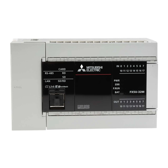
Page 16: Chapter 1 Outline
OUTLINE Part Names Front panel [10] [11] Name Description DIN rail mounting hooks Hook for mounting the CPU module on a DIN rail of DIN46277 (35 mm (1.38") wide). Expansion adapter connecting When connecting an expansion adapter, secure it with these hooks. hooks Terminal block cover Cover for protecting the terminal block. - Page 17 With cover open [10] Name Description Built-in RS-485 communication Terminal block for connection with RS-485-compatible devices terminal block RS-485 terminal resistor selector Switch for switching terminal resistance for built-in RS-485 communication. switch RUN/STOP/RESET switch Switch for operating the CPU module. (Page 114 Methods of running, stopping, and resetting) RUN: Runs the program STOP: Stops the program RESET: Resets the CPU module (hold the switch on the RESET side for approximately 1 second.)
-
Page 18: Side
Top side/bottom side Top side Bottom side Name Description CPU module fixing screw hole Screw holes for fixing the CPU module to the panel. (In the case of FX5U-64M/80M, there are four screw holes.) 1 OUTLINE 1.1 Part Names... -
Page 19: Chapter 2 Specifications
SPECIFICATIONS The CPU module specifications are explained below. Generic Specifications Item Specifications 0 to 55 (32 to 131 ) Operating ambient temperature -25 to 75 (-13 to 167 ) Storage ambient temperature Operating ambient humidity 5 to 95%RH, non-condensation Storage ambient humidity 5 to 95%RH, non-condensation *3*4 Vibration resistance... -
Page 20: Power Supply Specifications
Operation can be continued upon occurrence of instantaneous power failure for 10 ms or less. When the supply voltage is 200 V AC, the time can be change to 10 to 100 ms by editing the user program. Power fuse FX5U-32M 250 V, 3.15 A Time-lag fuse FX5U-64M, 250 V, 5 A Time-lag fuse FX5U-80M... -
Page 21: Input Specifications
The CPU module input specifications are explained below. 24 V DC Input (sink/source) The input points in the table below indicate the CPU module terminal points. Item Specifications No. of input points FX5U-32M 16 points FX5U-64M 32 points FX5U-80M 40 points... - Page 22 Item Specifications Input circuit configuration • When using service power supply Sink input wiring Source input wiring Fuse Fuse 100 to 240 V AC 100 to 240 V AC Input impedance Input impedance • When using external power supply Sink input wiring Source input wiring Fuse Fuse...
-
Page 23: Output Specifications
Output Specifications The CPU module output specifications are explained below. Relay output Item Output Specifications No. of output points FX5U-32MR/ 16 points FX5U-64MR/ 32 points FX5U-80MR/ 40 points Connection type Removable terminal block (M3 screws) Output type Relay External power supply 30 V DC or less 240 V AC or less ("250 V AC or less"... -
Page 24: Transistor Output
Transistor output Item Output specifications No. of output points FX5U-32MT/ 16 points FX5U-64MT/ 32 points FX5U-80MT/ 40 points Connection type Removable terminal block (M3 screws) Output type FX5U-MT/ES Transistor/sink output FX5U-MT/ESS Transistor/source output External power supply 5 to 30 V DC Max. -
Page 25: Performance Specifications
Performance Specifications Item Specification Control system Stored-program repetitive operation Input/output control system Refresh system (Direct access input/output allowed by specification of direct access input/output [DX, DY]) Programming Programming language Ladder diagram (LD), structured text (ST), function block diagram/ladder diagram (FBD/LD) specifications Programming extension function Function block (FB), structured ladder, label programming (local/global) - Page 26 Number of device points Item Base Max. number of points No. of user device Input relay (X) 1024 points The total number of X and Y assigned to input/output points is up to points 256 points. Output relay (Y) 1024 points Internal relay (M) 32768 points (can be changed with parameter) Latch relay (L)
-
Page 27: Built-In Analog Specifications
Built-in Analog Specifications The analog input/output specifications of the built-in analog function are explained below. For details on the analog built-in function, refer to MELSEC iQ-F FX5 User's Manual (Analog Control). Analog input Item Specifications Analog input points 2 points (2 channels) Analog input Voltage 0 to 10 V DC (input resistance 115.7 k) -
Page 28: Communication Specifications
Communication Specifications The built-in Ethernet and built-in RS-485 communication specifications are as explained below. Built-in Ethernet communication For details of built-in Ethernet communication, refer to the following. MELSEC iQ-F FX5 User's Manual (Ethernet Communication) MELSEC iQ-F FX5 User's Manual (SLMP) Item Specifications Data transmission speed... -
Page 29: External Dimensions
123 mm (4.85") Approx. 0.65 kg (1.43 lbs) • Exterior color Main body: Munsell 0.6B7.6/0.2 • Accessories Dust proof protection sheet Manual supplied with product FX5U-64M, FX5U-80M 4-4.5 mounting holes Unit: mm (inches) 8 (0.32") (0.87") 83 (3.27") Model W1 (mounting hole pitch) Mass (weight) FX5U-64M... -
Page 30: Terminal Layout
2.10 Terminal Layout Built-in RS-485 terminal European type terminal block 5 poles Built-in analog terminal European type terminal block 5 poles Analog Analog input output Built-in Ethernet connector Signal name Not used Not used Not used Not used 2 SPECIFICATIONS 2.10 Terminal Layout... - Page 31 One common terminal covers 4 or 8 output points. The output number (Y) connected to common is the range inside the thick "separation line." For transistor output (source) type, the "COM" terminal is the "+V" terminal. ■ FX5U-32M S/S 0V FX5U-32MR/ES, FX5U-32MT/ES...
- Page 32 ■FX5U-80M S/S 0V X40 42 FX5U-80MR/ES, FX5U-80MT/ES COM0 3 COM1 COM2 COM3 COM4 COM5 COM6 FX5U-80MT/ESS 2 SPECIFICATIONS 2.10 Terminal Layout...
-
Page 33: Chapter 3 Product List
PRODUCT LIST The following shows the system configuration equipment of the FX5U. Overall Configuration Expansion boards Battery • FX5-232-BD FX3U-32BL • FX5-485-BD • FX5-422-BD-GOT Expansion CPU module I/O module FX3 Intelligent function module adapters conversion Input/output Input Output Analog Network... -
Page 34: Cpu Module
CPU Module The CPU module incorporates a CPU, memory, input/output terminals, and power supply. FX5U Power supply, Input/output type: Connection on terminal block. • R/ES: AC power supply/24 V DC (sink/source) input/Relay output • T/ES: AC power supply/24 V DC (sink/source) input/Transistor (sink) output... -
Page 35: I/O Module
I/O Module The I/O module is used to expand inputs/outputs. For details, refer to Page 132 I/O Module. Input/output type • X/ES: 24 V DC (sink/source) input • YR/ES: Relay output • YT/ES: Transistor (sink) output • YT/ESS: Transistor (source) output Input/output extension Total number of •... -
Page 36: Intelligent Function Module
250 mA FX3 intelligent Function Module The following FX3 intelligent functions modules can be used in FX5U CPU module systems by using bus conversion modules. For the bus conversion modules to be connected, refer to Page 36 Bus Conversion Module. -
Page 37: Expansion Board
Network Model Function No. of occupied Current consumption input/output 5 V DC power 24 V DC External 24 V DC points supply power supply power supply FX3U-16CCL-M Master for CC-Link (compatible with Ver. 2.00 8 points 240 mA and Ver. -
Page 38: Extension Power Supply Module
[] temperature [] Bus Conversion Module The bus conversion module is to connect FX3 extension modules with FX5U CPU module systems. For details on the specifications of the bus conversion module, refer to MELSEC iQ-F FX5-CNV-BUS Hardware Manual. Model Function No. -
Page 39: Battery
Function FX-232CAB-1 FX5-232ADPPersonal computer FX5-232-BDPersonal computer 3.12 Engineering Tool For design and programming of FX5U CPU module systems, use GX Works3. For the operation method, refer to GX Works3 Operating Manual. Model Function GX Works3 MELSEC PLC software package 3 PRODUCT LIST... -
Page 40: Chapter 4 System Configuration
Expansion board FX5 extension power CPU module I/O module Intelligent module supply module Output Input Simple motion module module module FX5U-32MR/ES FX5-16EYR/ES FX5-16EX/ES FX5-1PSU-5V FX5-40SSC-S X000 to X017 X020 to X037 Expansion Module No.1 adapters Y000 to Y017 Y020 to Y037... -
Page 41: Rules Of System Configuration
Number of input/output points With the FX5U CPU module, a total of 512 points or less including the number of input/output points of extension devices (max. 256 points) and number of remote I/O points (max. 384 points) can be controlled. - Page 42 Current consumption Power of extension devices is supplied from the CPU module or extension power supply module. The number of extension devices that can be connected must be determined from the capacity of the power supply. For details on the current consumption, refer to Page 48 Limitation on Current Consumption. CPU module Input Powered...
-
Page 43: Limitations On The Number Of Connected Extension Devices
Limitations on the Number of Connected Extension Devices Number of connected expansion boards Only 1 expansion board can be connected on the front face of the CPU module. Expansion board Number of connected expansion adapters There is a limitation on the number of expansion adapter connected to the CPU module as follows. Type Limitations Communication adapter... -
Page 44: Number Of Connected Extension Modules
Number of connected extension modules Overall system limitation There is a limitation on the number of connected extension modules in a whole system as follows. Type Limitations Extension module Up to 16 modules can be connected to a system. (Extension power supply modules are excluded.) Extension power supply module Up to 2 modules can be connected to a system. - Page 45 Connection to the powered input/output module There is a limitation on the number of extension modules connected to the powered input/output module as follows. The number of connected modules from the right side of the powered input/output module the next extension power supply module added later must be as follows.
- Page 46 Connection to the bus conversion module (connection with FX3 extension devices) There is a limitation on the number of extension modules connected to the bus conversion module as follows. The number of modules connected on the right side of the bus conversion module must be as follows. ■When using FX3 extension power supply modules Type Limitations...
-
Page 47: Limitation On The Number Of Input/Output Points
Remote I/O station Total number of I/O points and remote I/O points With the FX5U CPU module, a total of 512 points or less including the number of input/output points of extension devices and number of remote I/O points can be controlled. -
Page 48: Calculation Of Number Of Input/Output Points
Precautions when using CC-Link master (FX3U-16CCL-M) and AnyWireASLINK master (FX3U-128ASL-M) together When using FX3U-16CCL-M and FX3U-128ASL-M together, connect FX3U-128ASL-M on the left side. In the FX5U CPU module, FX3U-16CCL-M parameters are set up by PLC program and will occupy up to 256 remote I/O points. Therefore, the remote I/O points of FX3U-128ASL-M that is connected to the right side may be less than 128 points when FX3U-16CCL-M is connected to the left side. - Page 49 I/O points stations × 32 points In the FX5U CPU module, FX3U-16CCL-M parameters are set up by PLC program and will occupy up to 256 remote I/O points. When the total number of the number of input/output points (including occupied input/output points) and the number of remote I/O points of FX3U-128ASL-M that is connected to the left side exceeds 256 points, the difference of 512 minus that total can be used as CC-Link remote I/O points.
-
Page 50: Limitation On Current Consumption
5 V DC power supply 24 V DC service power supply CPU module FX5U-32MT/ES 900 mA 400 mA *1 Value when service power supply is used for input circuits. The power supply capacity differs when external power supply is used for input circuit. -
Page 51: Power Supply Check From The Powered Input/Output Module (Current Consumption Calculation)
Check if expansion to the CPU module is permitted. • 5 V DC power supply Capacity of 5 V DC Current consumption Calculation result power supply Total of current CPU module consumed by extension module 0 mA mA ≥ 900 mA 510 mA 390 mA •... - Page 52 Check the number of input/output points and current consumption of the extension module. (Page 33 I/O Module) (Page 34 Intelligent Function Module) Type Model Current consumption 5 V DC power supply 24 V DC service power supply Input module FX5-16EX/ES 100 mA 85 mA Output module...
-
Page 53: Power Supply Check From Extension Power Supply Module (Current Consumption Calculation)
Power supply check from extension power supply module (current consumption calculation) If 5 V DC power supply of the CPU module is insufficient and cannot be extended, add an extension power supply module. Check if power can be supplied to extension modules with the power supply capacity of the extension power supply module. CPU module extension Expansion... - Page 54 When connecting an input module after (on the right side of) the extension power supply module When using service power supply of the CPU module or powered input/output module for input circuit of an input module, include the input module in the 24 V DC current consumption calculation. 5 V DC power supply of the input module is supplied from the extension power supply module.
-
Page 55: Rules Of System Configuration And Examples Of Reconfiguration
The rules of system configuration are explained below referring to a sample system configuration using an expansion board, expansion adapter, I/O module, and intelligent function module. System configuration example The following system configuration is under consideration. FX5U-32MR/ES CC-Link To CC-Link FX5-232-BD... - Page 56 • Number of modules connected to the CPU module (Page 42 Connection to the CPU module) Type No. of modules used Limitations Judgment Total No. of I/O modules, intelligent function modules, and bus conversion modules Up to 12 Total No. of intelligent function module and bus conversion modules Up to 8 •...
- Page 57 Check of limitation on the number of input/output points Check if the number of input/output points of the sample system configuration is within the limit range. ■Number of input/output points (Page 46 Calculation of number of input/output points) Type Model No.
- Page 58 • Power supply capacity of the CPU module Type Model Power supply capacity 5 V DC power supply 24 V DC service power supply CPU module FX5U-32MR/ES 900 mA 400 mA (Service power supply is used for input circuit) • Current consumption of extension devices Type Model...
-
Page 59: System Reconfiguration Example
If current consumption of the 5 V DC or 24 V DC power supply is insufficient with the CPU module only, powered input/output module or use an extension power supply module. Reconfigure the example system configuration using an extension power supply module. FX5U-32MR/ES To CC-Link CC-Link... - Page 60 • Number of modules connected to the bus conversion module (Page 44 Connection to the bus conversion module (connection with FX3 extension devices)) Type No. of modules used Limitations Judgment Total No. of intelligent function modules Up to 6 (When not using extension power supply modules) Check on limitations when using FX3 extension devices Check on limitations when using the FX3 extension devices.
- Page 61 ■Number of remote I/O points (Page 46 Calculation of number of remote I/O points) Network No. of remote I/O points AnyWireASLINK 64 points Maximum number of Remote I/O points Remote I/O points ≤ 384 points 64 points ■Total number of I/O points and remote I/O points (Page 45 Limitation on the Number of Input/Output Points) Max.
- Page 62 Power supply capacity of the CPU module Type Model Power supply capacity 5 V DC power supply 24 V DC service power supply CPU module FX5U-32MR/ES 900 mA 400 mA (Service power supply is used for input circuit) Current consumption of extension devices Type Model...
- Page 63 ■ Check of power supply from the extension power supply module (Page 51 Power supply check from extension power supply module (current consumption calculation)) Power supply capacity of the extension power supply module Type Model Power supply capacity 5 V DC power supply 24 V DC power supply FX5 extension power supply module FX5-1PSU-5V...
-
Page 64: Numbers And Assignment In System
Numbers and Assignment in System Input/output numbers and module numbers in an FX5U CPU module system are explained. Module input/output number The input/output numbers are octal numbers. Input is assigned to "X" and output to "Y." Input/output numbers are used for communication of ON/OFF data between I/O modules and the CPU module. -
Page 65: Chapter 5 Installation
Extension devices can be connected on the left and right sides of the CPU module of the PLC. Keep a space of at least 50 mm (1.97") between the module main body and other devices and structure. If you intend to add extension devices, keep necessary spaces on the left and right sides. FX5U CPU module ≥50 mm (1.97") -
Page 66: Examination For Installation Method In Enclosure
• The PLC installation height is the same as the DIN rail. For details on the procedures for installing on and detaching from DIN rail, refer to Page 65 Procedures for Installing on and Detaching from DIN Rail. ■Example of installation 2 mm (0.08") FX5U-32MR/ES FX5-16EX FX5-16EYT DIN rail Installing directly •... -
Page 67: Procedures For Installing On And Detaching From Din Rail
Procedures for Installing on and Detaching from DIN Rail The CPU module can be installed on a DIN46277 rail (35 mm (1.38") wide). Preparation for installation Connecting extension devices Some extension devices must be mounted on the CPU module before the module is installed in the enclosure. •... -
Page 68: Installation Of Extension Module
Installation of extension module Push out the DIN rail mounting hook (A in the right Rear panel figure) of the extension module. Fit the upper edge of the DIN rail mounting groove (B in the right figure) onto the DIN rail. Push the product against the DIN rail. -
Page 69: Procedures For Installing Directly (With M4 Screws)
The product mounting hole pitches are shown below. For pitch that varies depending on the product, refer to the table. CPU module Dimensions Model name Mounting hole pitch W Unit: mm (inches) " FX5U-32MR/ES 123 (4.85 (0.87") FX5U-32MT/ES 5 (0.2") FX5U-32MT/ESS FX5U-64MR/ES 193 (7.6") FX5U-64MT/ES (0.87") - Page 70 I/O module Dimensions Model name Mounting hole pitch W Unit: mm (inches) FX5-8EX/ES Refer to the figure shown to the left. 20 (0.87") 20 (0.87") FX5-8EYR/ES FX5-8EYT/ES FX5-8EYT/ESS FX5-16EX/ES FX5-16EYR/ES FX5-16EYT/ES FX5-16EYT/ESS FX5-32ER/ES 140 (5.52") 5 (0.2") 5 (0.2") FX5-32ET/ES FX5-32ET/ESS Extension power supply module Dimensions...
-
Page 71: Hole Pitches When Extension Module Connected
For the connection method of the expansion adapter, refer to Page 72 Connection method B - connection of an expansion adapter. The FX5U-32M is used as the CPU module in this example. Make mounting holes on the mounting surface according to the external dimensions diagram. -
Page 72: Installation Of Extension Module
Installation of extension module Make mounting holes on the mounting surface Rear panel Rear panel according to the external dimensions diagram. Push in the DIN rail mounting hook (A in the right figure) of the extension module. If the DIN rail mounting hook is not pushed in, the screw hole is covered, and the extension module cannot be mounted. -
Page 73: Connection Methods For Cpu Module And Extension Devices
For connection method for FX5 extension power supply module (FX5-1PSU-5V), refer to MELSEC iQ-F FX5-1PSU-5V HARDWARE MANUAL. Expansion Bus conversion Expansion extension module module extension module adapter board FX5U CPU module Connection Connection Connection Connection Connection Connection Connection method B... -
Page 74: Connection Method B - Connection Of An Expansion Adapter
Connection method B - connection of an expansion adapter This subsection explains how to connect the expansion adapter to the CPU module. Remove expansion adapter connector cover (A in the right figure). Slide the hook for coupling the expansion adapter of the CPU module (B in the right figure). -
Page 75: Connection Method D - Connection Between Extension Modules
Connection method D - connection between extension modules The procedure for connecting the extension modules is explained below. (Powered input/output module are excluded.) Remove the top cover (B in the right figure) of the existing module (left side) (A in the right figure). Connect the extension cable (C in the right figure) of the module to be connected (right side) to the existing module (left side) (A in the right figure). -
Page 76: Chapter 6 Wiring
WIRING Wiring Preparations Wiring procedure Before wiring, make sure that the source power supply is off. Prepare the parts for wiring. Prepare crimp terminals and cables needed for wiring. (Page 76 Cable Connecting Procedure) Wire the power supply terminals. Connect the cables to the power [L] and [N] terminals. Provide the protection circuit described in this chapter for the power supply circuit. -
Page 77: Removal And Installation Of Removable Terminal Block
Removal and installation of removable terminal block Removal Loosen terminal block mounting screws on the left and right sides uniformly and remove the terminal block. Installation Place the terminal block at its predetermined position and tighten the terminal block mounting screws on the left and right sides uniformly. -
Page 78: Cable Connecting Procedure
Cable Connecting Procedure The cable connecting procedure is explained below. Screw terminal block Wire the screw terminal block in accordance with the following specifications. For information concerning screw terminal blocks for intelligent function modules, refer to User's manual for each intelligent function module. -
Page 79: European-Type Terminal Block
European-type terminal block Wire the European-type terminal block in accordance with the following specifications. Suitable wiring Number of wires connected Wire size Tightening per terminal torque Solid wire, Stranded Wire ferrule with wire insulation sleeve Built-in analog I/O terminal block One wire 0.2 to 0.5 mm (AWG24 to 20) -
Page 80: Grounding
■Tool For tightening terminals, use a small, commercially-available screwdriver with a straight tip. The recommended shape is shown in the figure on the right. ■Precautions With straight tip When a precision screwdriver with a small grip is used, the specified tightening torque cannot be obtained. Use the following screwdriver or equivalent product (grip diameter: 25 mm (0.99")) to obtain the tightening torque specified above. -
Page 81: Power Supply Wiring
Power Supply Wiring Examples of AC power supply wiring Power supply example for sink input [-common] AC power supply (100 to 240 V) Expansion adapter 5 V 0 V 24 V Breaker CPU module Power ON Class D grounding 5 V 0 V 24 V Emergency stop 24 V DC... - Page 82 Power supply example for source input [+common] AC power supply (100 to 240 V) Expansion adapter 5 V 0 V 24 V Breaker CPU module Power ON Class D grounding 5 V 0 V 24 V Emergency stop 24 V DC service power supply Input module S/S...
- Page 83 Wiring example for an extension power supply module (sink input [-common]) The following example shows wiring for an extension power supply module when sink input [-common] is used. AC power supply (100 to 240 V) Expansion adapter 5 V 0 V 24 V Breaker CPU module Power ON...
- Page 84 Wiring example for an extension power supply module (source input [+common]) The following example shows wiring for an extension power supply module when source input [+common] is used. AC power supply (100 to 240 V) Expansion adapter 5 V 0 V 24 V Breaker CPU module Power ON...
-
Page 85: Input Wiring
Input Wiring The input wiring of the CPU module and I/O modules is explained below. 24 V DC input (Sink and source input type) For input specifications of the CPU module, refer to Page 19 Input Specifications. For input specifications of the I/O modules, refer to Page 135 Input specifications. Sink and source input ■Differences between the sink input circuit and the source input circuit •... - Page 86 Input has a response delay switching from ON to OFF and OFF to ON, shown in the following table. Item Specifications ON: 2.5 s or less Input response time FX5U-32M X000 to X005 OFF: 2.5 s or less (H/W filter delay) FX5U-64M, X000 to X007 FX5U-80M...
- Page 87 The voltage drop of the series diode should be the following value or less. Also make sure that the input current is over the input-sensing level while the switches are on. Item Specifications Voltage drop FX5U-32M X000 to X005 3.9 V FX5U-64M, X000 to X007 FX5U-80M...
- Page 88 (for input current adjustment) In the case of capturing high-speed pulses When capturing pulses of a response frequency of 50 to 200 kHz on using the input X000 to X007 (FX5U-32M is X000 to X005.), wire the terminals as stated below.
-
Page 89: Input Wiring Example
Input wiring example Sink input [AC power supply type] CPU module Fuse Class D grounding Three-wire sensor Input Input terminal impedance 5V 0V 24V Input module Two-wire proximity sensor 5V 0V 24V Input terminal Input module 24 V DC Three-wire 5V 0V 24V sensor Input... - Page 90 Source input [AC power supply type] CPU module Fuse Class D grounding Three-wire sensor Input Input impedance terminal 5V 0V 24V Two-wire Input module proximity sensor 5V 0V 24V Input terminal Input module 24 V DC Three-wire sensor 5V 0V 24V Input terminal *1 Handle the power supply circuit properly in accordance with "Power Supply Wiring."...
-
Page 91: Output Wiring
Output Wiring The output wiring of the CPU module and I/O modules is explained below. Relay output For output specifications of the CPU module, refer to Page 21 Output Specifications. For output specifications of the I/O modules, refer to Page 136 Output specifications. Product life of relay output contacts The product life of relay output contacts varies considerably depending on the load type used. - Page 92 Handling of relay output ■Output terminal One common terminal is used for 4 or 8 relay output points. The common terminal blocks can drive loads of different circuit voltage systems (for example,100 V AC and 24 V DC). Load 24 V DC Fuse COM0 Load...
- Page 93 Wiring precautions ■Protection circuit for load short-circuiting A short-circuit at a load connected to an output terminal could cause Load burnout at the output element or the PCB. To prevent this, a protection fuse should be inserted at the output. Fuse COM0 PLCs...
-
Page 94: Transistor Output
Transistor output For output specifications of the CPU module, refer to Page 21 Output Specifications. For output specifications of the I/O modules, refer to Page 136 Output specifications. Sink and source output Sink output and source output products are available for transistor outputs of the CPU module and I/O modules. ■Differences in circuit •... - Page 95 ■Response time Time taken from when the photocoupler of the module is driven (or shut off) to when the transistor is turned on (or off) differs depending on the output terminal used. For specifications of each module, refer to the following. For output specifications of the CPU module, refer to Page 21 Output Specifications.
- Page 96 ■Contact protection circuit for inductive loads When an inductive load is connected, connect a diode (for commutation) in parallel with the load as necessary. The diode (for commutation) must comply with the following specifications. Standard Reverse voltage 5 to 10 times as high as the load voltage Forward current Load current or larger Sink output type...
-
Page 97: Output Wiring Example
Output wiring example Relay output AC power supply (100 to 240 V) CPU module Fuse relay output COM0 Breaker Power ON Fuse COM1 Fuse COM3 Emergency stop Output module Fuse COM0 relay output DC power supply Load Fuse COM1 Load Power supply for loads connected to PLC output terminals As for emergency stop operation, see "DESIGN... - Page 98 Transistor output ■Sink output type CPU module transistor AC power supply (100 to 240 V) output (sink) Fuse COM0 Breaker Load COM1 Power ON Fuse COM3 Emergency Load stop Output module transistor output (sink) Fuse COM0 DC power supply Load Fuse COM1 Load...
- Page 99 ■Source output type CPU module transistor AC power supply (100 to 240 V) output (source) Fuse Breaker Load Power ON Fuse Emergency Load stop Output module transistor output (source) Fuse DC power supply Load Fuse Load Power supply for loads connected to PLC output terminals As for emergency stop operation, see "DESIGN PRECAUTIONS"...
-
Page 100: Analog Wiring
Analog Wiring Wiring to the built-in analog I/O terminals of the CPU module is explained below. For specifications of the built-in analog I/O terminals of the CPU module, refer to Page 25 Built-in Analog Specifications. Analog input wiring CH Shield 82.7 k... -
Page 101: Examples Of Wiring For Various Uses
Examples of Wiring for Various Uses Notes about examples of wiring The examples of wiring are given under the following conditions. ■Input/output number The input/output numbers are the actual numbers on the program (They may differ from the numbers shown on the product terminals). -
Page 102: High-Speed Counter
High-speed counter Examples of wiring for high-speed counters are shown below. When capturing pulses of a response frequency of 50 to 200 kHz, refer to Page 86 In the case of capturing high-speed pulses. For details on the high-speed counters, refer to MELSEC iQ-F FX5 User's Manual (Application). For the programs, refer to MELSEC iQ-F FX5 Programming Manual (Instructions, Standard Functions/Function Blocks). - Page 103 ■Example of wiring (When 24 V DC external power supply is used) • NPN open collector transistor output rotary encoder In the case of sink wiring Rotary encoder 24 V DC Fuse Class D grounding A phase 1.5 k B phase X000 Z phase CPU module...
- Page 104 2-phase 2-count The wiring examples in this section use the following settings. When settings other than those in the table are used, use the examples shown in the following figures as references for wiring. CH to be used Pulse input mode External preset input External enable input Operation mode 2-phase 2-input...
- Page 105 ■Example of wiring (When 24 V DC external power supply is used) • NPN open collector transistor output rotary encoder In the case of sink wiring Rotary encoder 24 V DC Fuse Class D grounding 1.5 k A phase X002 B phase X003 Z phase...
-
Page 106: Interruption
Interruption Examples of wiring for when the input interruption function of the CPU module is used are shown below. The same wiring is used for the pulse catch and pulse width measurement functions. When capturing pulses of a response frequency of 50 to 200 kHz, refer to Page 86 In the case of capturing high-speed pulses. -
Page 107: Digital Switch
For the instructions, refer to MELSEC iQ-F FX5 Programming Manual (Instructions, Standard Functions/Function Blocks). ■Example of program SM400 X010 Y010 D100 ■Example of wiring • Sink wiring The example is the wiring for the input/output of the FX5U-32MT/ES. Digital switch of 0.1A 50V diode is necessary. X010 X011 X012 X013 X014... - Page 108 For the instructions, refer to MELSEC iQ-F FX5 Programming Manual (Instructions, Standard Functions/Function Blocks). ■Example of program SM400 K2X010 D102 ■Example of wiring • Sink wiring The example is the wiring for the input/output of the FX5U-32MT/ES. X010 X011 X012 X013 X014 X015 X016 X017 Sink input FX5U-32MT/ES •...
-
Page 109: Input Matrix
For the instructions, refer to MELSEC iQ-F FX5 Programming Manual (Instructions, Standard Functions/Function Blocks). Example of program SM400 X010 Y010 Example of wiring • Sink wiring The example is the wiring for the input/output of the FX5U-32MT/ES. X011 X013 X015 X017 X012 X014 X016 0.1A 50V... -
Page 110: Seven Segment With Latch
Examples of wiring for displaying the current value of D100 on the 4-digit 7-segment display are given below. ■Example of program SM400 SEGL D100 Y010 ■Example of wiring • Sink wiring The example is the wiring for the input/output of the FX5U-32MT/ES. FX5U-32MT/ES Transistor output (sink) COM2 Y010 Y011 Y012 Y013... - Page 111 Examples of wiring for displaying the current value of D100 on the 2-digit 7-segment display are given below. ■Example of program SM400 D100 K2Y010 ■Example of wiring • Sink wiring The example is the wiring for the input/output of the FX5U-32MT/ES. FX5U-32MT/ES Transistor output (sink) COM2 Y010 Y011...
-
Page 112: Chapter 7 Operation Adjustment
OPERATION ADJUSTMENT Preparation for Operation Preliminary inspection Incorrect connection of the power supply terminal, contact of the DC input wire and power supply wire, or short-circuiting of output wires may result in serious damage. Before applying power, check that the power supply and ground terminals are connected correctly and input/output devices are wired properly. -
Page 113: Procedure Until Operation
Procedure until operation The procedure until operation is explained below. Turn on the power of the system. Check the following items before turning on the power of the system. When the CPU module with the factory default setting is powered on, the ERR LED flashes because the module has no programs. •... -
Page 114: Connection With A Personal Computer
Connection with a personal computer Connect the CPU module with a personal computer on which an engineering tool has been installed. The system configuration examples and GX Works3 settings are described below. For details, refer to GX Works3 Operating Manual. Direct connection Setting examples for accessing the CPU module that is directly connected with a personal computer are shown below. -
Page 115: Operation And Test
■Serial connection FX5-232ADP FX5-232-BD COM port COM port (COM1) (COM1) RS-232 cable RS-232 cable (FX-232CAB-1) (FX-232CAB-1) GX Works3 settings Item Selection item Internal setting Input value PC side I/F Serial/USB RS-232C COM Port COM1 Transmission Speed 115.2Kbps PLC side I/F PLC Module PLC Mode FX5CPU... -
Page 116: Running, Stopping, And Resetting
Running, Stopping, and Resetting Methods of running, stopping, and resetting The following two methods of running, stopping, and resetting the FX5U CPU modules are provided. Using the RUN/STOP/RESET switch The operation status of the CPU module can be changed with the RUN/STOP/RESET switch. -
Page 117: Chapter 8 Maintenance And Inspection
MAINTENANCE AND INSPECTION To keep using the PLC in the optimal condition, perform the following inspections daily or periodically. Daily Inspection Perform the following inspections on a daily basis. Item Inspection item Description Installation status Looseness of mounting screws Retighten the mounting screws. of the module Mounting status of the module The module should be securely mounted. -
Page 118: Battery
Battery Part names The Latch device memory and clock data upon power interruption. The battery is not incorporated in the CPU module during shipment from the factory. Order it if necessary. Parameter setting is required to back up the device memory and clock data. (Page 117 Setting an optional battery using the engineering tool) External appearance Name... - Page 119 Insert the battery connector (B in the figure below) of the battery. Set the battery inside the lower hook (C in the following figure), push up the upper hook (D in the following figure), and then fit the battery in the battery holder (E in the following figure). The following figure shows the position of the battery.
-
Page 120: Battery Replacement
Battery replacement Battery life and replacement guidelines When the battery voltage is low, the BAT LED is lit red while the power is on, and SM51 (SM8005) and SM52 (SM8006) are turned ON. The memory can be retained for about one month after the LED is turned on. However, the drop in battery voltage may not be detected immediately. -
Page 121: Special Relay For Low Battery Voltage
Extract the old battery from the battery holder ("B" in figure below), and disconnect the battery connector ("C" in figure below). Install the new battery. (Page 116 Battery attachment) Attach the expansion board connector cover. If an expansion board was removed in step 2, reinstall it. •... -
Page 122: Chapter 9 Troubleshooting
Reconnect the modules and wire one by one to identify the cause. If the PWR LED still does not turn on even after the items shown above are checked, there may be a hardware issue. Consult your local Mitsubishi Electric representative. Checking the BAT LED If the BAT LED is turned on, check the following items. -
Page 123: Checking The Err Led
• Fit a noise filter onto the power supply line. If the ERR LED still does not turn off even after the items shown above are checked, there may be a hardware issue. Consult your local Mitsubishi Electric representative. Checking the P.RUN LED If the P.RUN LED is turned off, check the status of the ERR LED and take corrective actions. -
Page 124: Module Diagnostics (Cpu Diagnostics)
Module diagnostics (CPU Diagnostics) This function diagnoses CPU module, expansion adapter, and expansion board. (The current error and its details can be checked.) Information required for troubleshooting, such as the current error, details and cause of the error, and action to be taken, are displayed. -
Page 125: Error Status And Operations On Occurrence Of An Error
Stop The module is unable to continue its operation due to a Perform troubleshooting. If the error still persists, hardware issue. consult your local Mitsubishi Electric representative. Moderate Stop The module is unable to carry out programs or continue the... -
Page 126: Backing Up The Data
Backing Up the Data Saving the following information immediately after the occurrence of an error helps in analyzing the cause of the error. • Parameters, programs, and device memory • Error histories Backing up parameters, programs, and device memory The procedure for backing up parameters, programs, and device memory using the engineering tool is explained below. [Online][Read from PLC] Check the parameters, programs, and device memory to back up. -
Page 127: Troubleshooting For Each Symptom
The output may be turned off unintentionally in the program. Review user program (Duplicate coils or RST instructions). ■When the output does not turn off There may be a hardware fault. Consult your local Mitsubishi Electric representative. Input does not turn on... -
Page 128: Plc Write, Plc Read
The boot operation may be being performed. Read the parameters and review the boot file settings with the engineering tool. If the boot operation is not being performed, there may be a hardware issue. Consult your local Mitsubishi Electric representative. -
Page 129: Appendix
APPENDIX Appendix 1 How to Check the Date of Manufacture Check the date of manufacture of the product (except the expansion board) as follows. • Nameplate • Module front surface (CPU module only) Checking the nameplate The date of manufacture of the product can be checked from the manufacturer's serial number "S/N" indicated on the nameplate of the product. -
Page 130: Appendix 2 Standards
Compliance to EMC directive and LVD directive of the entire mechanical module should be checked by the user/ manufacturer. For more details please contact to the local Mitsubishi Electric sales site. Requirement for compliance with EMC directive... -
Page 131: Requirement For Compliance With Lvd Directive
Installation in enclosure FX5U CPU modules are open-type devices that must be installed and used within shielded conductive control boxes. Please use the PLCs while installed in conductive shielded control boxes. Please secure the control box lid to the control box (for conduction). - Page 132 Mitsubishi Electric recommends that shielded cables be used. If no other EMC protection is provided, users may experience temporary loss of accuracy between +10%/-10% in very heavy industrial areas.
- Page 133 Caution for when the built-in Ethernet port is used • Use a shielded twisted pair cable for the 10BASE-T or 100BASE-TX cable. Strip a part of the jacket of the shielded twisted pair cable as shown below and ground as much of the exposed shield as possible to both sides of the cable. •...
-
Page 134: Appendix 3 I/O Module
Appendix 3 I/O Module Product configuration There are various types of I/O module. They differ in supply voltage, number of input/output points, input form, output form and connection type. I/O module Number of Power supply Input type Output type Connection form input/output points PLC internal 24 V DC... -
Page 135: Specifications
Powered input/output module : Sink, : Source Sink Source Model Input Output Connection type Type No. of points Common wiring Type No. of points Common wiring system system ■Input/output extension/sink and source input/relay output type Sink Source FX5-32ER/ES 24 V DC Relay Terminal block ■Input/output extension/sink and source input/sink output only... - Page 136 External color, weight, accessories ■Input module/output module Item Specifications External color Munsell 0.6B7.6/0.2 Mass (weight) FX5-8E Approx. 0.2 kg (0.44 lbs) FX5-16E Approx. 0.25 kg (0.55 lbs) Accessories Dust proof protection sheet ■Powered input/output module (FX5-32E) Item Specifications External color Munsell 0.6B7.6/0.2 Mass (weight) Approx.
- Page 137 Input specifications There is the simultaneous ON ratio of available PLC inputs or outputs with respect to the ambient temperature. For details, refer to Page 22 Input/Output Derating Curve Item Specifications No. of input points FX5-8EX/ES 8 points FX5-16EX/ES 16 points FX5-32E...
- Page 138 Item Specifications Input circuit configuration • When using external power supply by input module Sink input wiring Source input wiring CPU module CPU module Input module Input module 5.6 k 5.6 k • When using external power supply by powered input/output module Sink input wiring Source input wiring Powered input/output module...
- Page 139 ■Transistor output (sink output) Item Specifications No. of output points FX5-8EYT/ES 8 points FX5-16EYT/ES 16 points FX5-32ET/ES 16 points Connection type Terminal block (M3 screws) Output type Transistor/sink output External power supply 5 to 30 V DC Output circuit insulation Photo-coupler insulation Indication of output operation LED is lit when output is on...
-
Page 140: External Dimensions And Component Names
External dimensions and component names Input module/output module (mounting hole pitch) Unit: mm (inches) 83 (3.27") Without cover 8 (0.32") 2-4.5 mounting holes External dimensions Model W: mm (inches) FX5-8EX/ES 40 (1.58") FX5-8EYR/ES, FX5-8EYT/ES, FX5-8EYT/ESS FX5-16EX/ES FX5-16EYR/ES, FX5-16EYT/ES, FX5-16EYT/ESS Part names Name Description Input display LED, output display LED... - Page 141 Powered input/output module 2-4.5 mounting holes [5] [6] Unit: mm (inches) 140 (5.52") (mounting hole pitch) 8 (0.32") 83 (3.27") (mounting hole pitch) [Without cover] [10] External dimensions Model W: mm (inches) FX5-32ER/ES, FX5-32ET/ES, FX5-32ET/ESS 150 (5.91") Part names Name Description Extension connector cover (for preceding module) Cover for protecting the extension connector cover (for preceding module).
-
Page 142: Terminal Layout
Terminal layout FX5-8EX/ES FX5-8EYR/ES FX5-8EYT/ESS FX5-8EYT/ES FX5-16EX/ES FX5-16EYR/ES FX5-16EYT/ESS FX5-16EYT/ES Lower Lower Lower numbers numbers numbers Higher Higher Higher number number number FX5-32E S/S 0V FX5-32ER/ES, FX5-32ET/ES COM0 COM1 COM2 COM3 FX5-32ET/ESS APPENDIX Appendix 3 I/O Module... -
Page 143: Appendix 4 Sd Memory Card
Appendix 4 SD Memory Card Part names An SD memory card is installed in the CPU module to operate the module based on the project data in the card. Name Description Write protect switch Setting the switch in the lock position prevents the data in the SD memory card from being deleted and overwritten. Specifications The following shows functional specifications of the SD memory card. -
Page 144: Insertion And Removal Of The Sd Memory Card
Insertion and removal of the SD memory card The following explains insertion and removal of the SD memory card. Insertion procedure Mount the SD memory card. Pay attention to the direction of the card and follow the procedure below. Insert the SD memory card (1) straight into the SD memory card slot. Make sure that the notch of the card is directed downward. -
Page 145: Appendix 5 Precautions For Battery Transportation
When transporting lithium batteries, follow required transportation regulations. Batteries used in the FX5U CPU module are classified as follows. Control-subject product Built-in None (FX5U CPU modules do not include batteries when shipped from the factory.) Battery only (spare parts and optional parts) Model Battery type... -
Page 146: Appendix 6 Handling Of Batteries And Devices With Built-In Batteries In Eu Member States
Appendix 6 Handling of Batteries and Devices with Built-in Batteries in EU Member States This section describes the precautions for disposing of waste batteries in EU member states and exporting batteries and/or devices with built-in batteries to EU member states. Disposal precautions In EU member states, there is a separate collection system for waste batteries. -
Page 147: Index
INDEX ..15 RS-485 terminal resistor selector switch ... . . 15,114 RUN/STOP/RESET switch ......14 BAT LED . -
Page 148: Revisions
3.12, Chapter 4, Section 5.4, 5.5, 6.1, 6.6, 7.1, 7.3, 8.2, 8.3, 9.1, 9.2, 9.3, 9.7, Appendix 2, 4 This manual confers no industrial property rights or any rights of any other kind, nor does it confer any patent licenses. Mitsubishi Electric Corporation cannot be held responsible for any problems involving industrial property rights which may occur as a result of using the contents noted in this manual. -
Page 149: Warranty
WARRANTY Please confirm the following product warranty details before using this product. Gratis Warranty Term and Gratis Warranty 2. Onerous repair term after discontinuation of production Range If any faults or defects (hereinafter "Failure") found to Mitsubishi shall accept onerous product repairs for be the responsibility of Mitsubishi occurs during use of seven (7) years after production of the product is the product within the gratis warranty term, the... -
Page 150: Trademarks
TRADEMARKS Microsoft and Windows are either registered trademarks or trademarks of Microsoft Corporation in the United States and/or other countries. Ethernet is a trademark of Xerox Corporation. Anywire is a registered trademark of the Anywire Corporation. MODBUS is a registered trademark of Schneider Electric SA. - Page 152 Manual number: JY997D55301B Model: FX5U-U-HW-E Model code: 09R536 When exported from Japan, this manual does not require application to the Ministry of Economy, Trade and Industry for service transaction permission. HEAD OFFICE: TOKYO BUILDING, 2-7-3 MARUNOUCHI, CHIYODA-KU, TOKYO 100-8310, JAPAN HIMEJI WORKS: 840, CHIYODA MACHI, HIMEJI, JAPAN Specifications are subject to change without notice.
Need help?
Do you have a question about the FX5U and is the answer not in the manual?
Questions and answers