Mitsubishi Electric MELSEC iQ-F FX5UC Series Hardware Manual
Cpu module
Hide thumbs
Also See for MELSEC iQ-F FX5UC Series:
- User manual (988 pages) ,
- Handbook (178 pages) ,
- Reference manual (48 pages)
Table of Contents
Advertisement
Quick Links
Side
B
Side
Side
A
B
JAPANESE
ENGLISH
MELSEC iQ-F FX5UC CPU Module
Hardware Manual
Manual Number
JY997D61001
Revision
G
Date
January 2019
This manual describes the part names, dimensions, installation, cabling and
specifications for the product. This manual is extracted from MELSEC iQ-F
FX5UC User's Manual (Hardware). Refer to MELSEC iQ-F FX5UC User's
Manual (Hardware) for more details. Before use, read this manual and
manuals of relevant products fully to acquire proficiency in the handling and
operating the product. Make sure to learn all the product information, safety
information, and precautions.
And, store this manual in a safe place so that you can take it out and read it
whenever necessary. Always forward it to the end user.
Registration: Ethernet is a trademark of Xerox Corporation. MODBUS
registered trademark of Schneider Electric SA. The company name and the
product name to be described in this manual are the registered trademarks or
trademarks of each company.
Effective January 2019
Specifications are subject to change without notice.
©
2015 MITSUBISHI ELECTRIC CORPORATION
Safety Precautions
(Read these precautions before use.)
If the equipment is used in a manner not specified by the manufacturer, the
protection provided by the equipment may be impaired.
This manual classifies the safety precautions into two categories:
and
.
Indicates that incorrect handling may cause hazardous
conditions, resulting in death or severe injury.
Indicates that incorrect handling may cause hazardous
conditions, resulting in minor or moderate injury or
property damage.
Depending on the circumstances, procedures indicated by
also cause severe injury.
It is important to follow all precautions for personal safety.
STARTUP AND
MAINTENANCE
PRECAUTIONS
• Do not touch any terminal while the PLC's power is on.
Doing so may cause electric shock or malfunctions.
• Before cleaning or retightening terminals, cut off all phases of the power
supply externally. Failure to do so in the power ON status may cause
electric shock.
• Before modifying the program in operation, forcible output, running or
stopping the PLC, read through this manual carefully, and ensure
complete safety.
An operation error may damage the machinery or cause accidents.
• Do not change the program in the PLC from two or more peripheral
equipment devices at the same time. (i.e. from an engineering tool and a
GOT) Doing so may cause destruction or malfunction of the PLC program.
• Use the battery for memory backup in conformance to the MELSEC iQ-F
FX5UC User's Manual (Hardware).
- Use the battery for the specified purpose only.
- Connect the battery correctly.
- Do not charge, disassemble, heat, put in fire, short-circuit, connect
reversely, weld, swallow or burn the battery, or apply excessive forces
(vibration, impact, drop, etc.) to the battery.
JY997D61001G
STARTUP AND
MAINTENANCE
PRECAUTIONS
- Do not store or use the battery at high temperatures or expose to direct
sunlight.
- Do not expose to water, bring near fire or touch liquid leakage or other
contents directly.
- When replacing the battery, make sure to use our specified product
(FX3U-32BL).
- When a battery error occurs ("BAT" LED is lit in red), follow the
description in MELSEC iQ-F FX5UC User's Manual (Hardware).
Incorrect handling of the battery may cause heat excessive generation,
bursting, ignition, liquid leakage or deformation, and lead to injury, fire or
failures and malfunction of facilities and other equipment.
STARTUP AND
MAINTENANCE
PRECAUTIONS
• Do not disassemble or modify the PLC.
Doing so may cause fire, equipment failures, or malfunctions.
For repair, contact your local Mitsubishi Electric representative.
• Turn off the power to the PLC before connecting or disconnecting any
extension cable.
Failure to do so may cause equipment failures or malfunctions.
• Turn off the power to the PLC before attaching or detaching the following
devices. Failure to do so may cause equipment failures or malfunctions.
- Peripheral devices, expansion adapter, and connector conversion adapter
- Extension modules, bus conversion module, connector conversion
module, and battery
• Do not use the chemicals for cleaning.
• If there is the possibility of touching the PLC inside a control panel in
maintenance, make sure to discharge to avoid the influence of static electricity.
• Since there are risks such as burn injuries, please do not touch the
surface of the equipment with bare hands when it is operating in an
environment which exceeds ambient temperature of 50°C.
is a
DISPOSAL PRECAUTIONS
• Please contact a certified electronic waste disposal company for the
environmentally safe recycling and disposal of your device.
• When disposing of batteries, separate them from other waste according to
local regulations. (For details on the Battery Directive in EU countries,
refer to the MELSEC iQ-F FX5UC User's Manual (Hardware).)
TRANSPORTATION
PRECAUTIONS
• When transporting the PLC with the optional battery, turn on the PLC
before shipment, confirm that the battery mode is set using a parameter
and the BAT LED is OFF, and check the battery life.
If the PLC is transported with the BAT LED ON or the battery exhausted,
the battery-backed data may be unstable during transportation.
• The PLC is a precision instrument. During transportation, avoid impacts
larger than those specified in the general specifications (Section 2.1) by
using dedicated packaging boxes and shock-absorbing palettes. Failure to
do so may cause failures in the PLC.
After transportation, verify operation of the PLC and check for damage of
the mounting part, etc.
may
• When transporting lithium batteries, follow required transportation
regulations. (For details on the regulated products, refer to the MELSEC
iQ-F FX5UC User's Manual (Hardware).)
Associated manuals
How to obtain manuals
For the necessary product manuals or documents, consult with your local
Mitsubishi Electric representative.
Associated manuals
FX5UC CPU module comes with this document (hardware manual).
For a detailed explanation of the FX5UC CPU module hardware and
information on instructions for PLC programming and intelligent function
module, refer to the relevant documents.
Manual name
Manual No.
Explains performance
MELSEC iQ-F FX5
specifications, procedures before
User's Manual
JY997D58201
operation, and troubleshooting of
(Startup)
the FX5 CPU module.
MELSEC iQ-F FX5UC
Explains FX5UC CPU module
User's Manual
JY997D61401
specification details for I/O, wiring,
(Hardware)
installation, and maintenance.
Manual name
Manual No.
MELSEC iQ-F FX5
User's Manual
JY997D55901
(Serial Communication)
MELSEC iQ-F FX5
User's Manual
JY997D56101
(MODBUS Communication)
MELSEC iQ-F FX5
User's Manual
JY997D56201
(Ethernet Communication)
Certification of UL, cUL standards
Please consult with Mitsubishi Electric for information on UL, cUL standard
practices and the corresponding types of equipment.
Compliance with EC directive (CE Marking)
This product complies with EC directive, however, this document does not guarantee
that a mechanical system including this product will comply with EC directive.
Compliance to EMC directive and LVD directive of the entire mechanical
system should be checked by the user/manufacturer. For more details please
contact the local Mitsubishi Electric sales site.
Caution for compliance with EC Directive
• Please use the FX5UC CPU modules while installed in conductive shielded
control panels under a general industrialenvironment.
• Programmable controllers are open-type devices that must be installed and
used within conductive control panels. Please secure the control box lid to
the control box (for conduction). Installation within a control box greatly
affects the safety of the system and aids in shielding noise from the
programmable controller.
• For the control panel, use the product having sufficient strength, fire
protectiveness and shielding property to an installation environment.
• 24 V DC of the power supply must be supplied from the circuit double/
reinforced insulated from the main power supply (MAINS).
[Caution for compliance with the LVD directive (EN61010-2-201:2013)]
• To an external connection port other than AC power supply terminal and AC
input/output terminal, connect the circuit separated from a dangerous
voltage by a double/reinforced insulation.
• Do not wire two or more crimp terminals to one terminal. (If the wiring with
two or more wires is needed, take an appropriate action such as adding an
external terminal.)
• For crimp terminals to be used for the wiring applied with 30 V AC or higher,
use the products with insulating sleeves.
• Cutoff device such as a breaker or a circuit protector should be installed in
accordance with the following precautions.
- Use EN60947-1 or EN60947-3 standards.
- Place the cutoff device so that it can be operated easily.
- Specify that the cutoff device is for this equipment.
*1 For the time of compliance with the LVD directive (EN61010-2-201:2013),
refer to MELSEC iQ-F FX5UC User's Manual (Hardware).
Incorporated Items
Check if the following product and items are included in the package:
CPU module
Product
FX2NC-100MPCB [1 m, three wire]
FX5UC-MT/D
FX2NC-100BPCB [1 m, two wire]
(: 32, 64, 96)
Manuals [Japanese/English]
Manuals [Chinese]
Product
FX5UC-MT/DSS
FX5UC-32MT/DS-TS
FX2NC-100MPCB [1 m, three wire]
FX5UC-32MT/DSS-TS
Description
Manuals [Japanese/English]
FX5UC-32MR/DS-TS
(: 32, 64, 96)
Manuals [Chinese]
Description
Explains the N:N network,
I/O module
MELSEC Communication
FX5-CEX/D
protocol, inverter communication
and non-protocol communication.
FX5-C32ET/D
(: 16, 32)
Explains the MODBUS serial
FX5-CEX/DS
communication.
FX5-C32EX/DS-TS
FX5-C32ET/DSS
Functions for communication via
FX5-C32ET/DS(S)-TS
built-in Ethernet port.
FX5-CEYT/D(SS)
FX5-C32EYT/D(SS)-TS
FX5-C16EYR/D-TS
(: 16, 32)
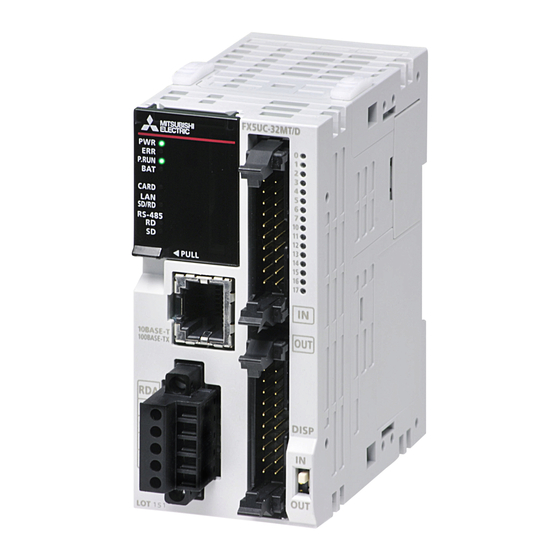
1. Outline
1.1 Part names
Front panel
(Connector type)
[5]
[1]
[4]
[3]
[2]
[1]
[10]
[9]
Left side
*1
[19]
With cover open
[26]
[25]
[24]
Included Items
No.
[1]
Expansion adapter connecting hooks
1 module
[2]
Built-in RS-485 communication terminal block
1 cable
[3]
Built-in Ethernet communication connector (with cover)
1 cable
Operation status display LEDs
1 manual
PWR
Green On while the PLC is powered.
1 manual
*1
Red
ERR
1 module
P.RUN
Green On while the PLC is running.
1 cable
BAT
Red
1 manual
[4]
CARD
Green Lit when the SD memory card is inserted.
1 manual
SD/RD Green
RD
Green
SD
Green
Included Items
Product
1 module
FX2NC-10BPCB1 [0.1 m, double-
1 cable
ended]
Product
1 module
Front panel
Under side
(Spring clamp
terminal block type)
[11]
[6]
[12]
[7]
[17]
[16]
[15]
[13]
[8]
[6]
[14]
[18]
Right side
[20]
[21]
[22]
[23]
Name
Lit/flashing when an error occurs.
Lit when the battery voltage drops.
Lit when data is sent or received through
communication via built-in Ethernet.
Lit when data is received through communication via
built-in RS-485.
Lit when data is sent through communication via
built-in RS-485.
Advertisement
Table of Contents

Related Manuals for Mitsubishi Electric MELSEC iQ-F FX5UC Series


Summary of Contents for Mitsubishi Electric MELSEC iQ-F FX5UC Series
- Page 1 Certification of UL, cUL standards (: 16, 32) STARTUP AND Hardware Manual MAINTENANCE Please consult with Mitsubishi Electric for information on UL, cUL standard 1. Outline PRECAUTIONS practices and the corresponding types of equipment. • Do not disassemble or modify the PLC.
- Page 2 *1 The simultaneous ON ratio of available PLC inputs or outputs changes 2) Fit the upper edge of the DIN rail mounting groove (right fig. B) onto the Name with respect to the ambient temperature. In the case where operating DIN rail.
- Page 3 2.6 Connection to input/output terminal block 2) Treatment of wire ends 3.1.2 Example of external wiring Strip the coating of strand wire and twist the cable core before connecting WIRING PRECAUTIONS 24 V DC power is supplied to the CPU module. CPU module supplies power The input/output terminal blocks of the products which have -TS at the end of it, or strip the coating of single wire before connecting it.
- Page 4 *4 The CC-Link IE field network Basic, FTP server, SNTP client, Web server Item Specification nor does it confer any patent licenses. Mitsubishi Electric Corporation cannot be and simple CPU communication function are not included in the number held responsible for any problems involving industrial property rights which may 30 V DC or less of connections.
Need help?
Do you have a question about the MELSEC iQ-F FX5UC Series and is the answer not in the manual?
Questions and answers