Mitsubishi Electric MELSEC iQ-F Series User Manual
Programmable
Hide thumbs
Also See for MELSEC iQ-F Series:
- Programming manual (1472 pages) ,
- User manual (954 pages) ,
- Handbook (132 pages)
Table of Contents
Advertisement
Quick Links
MELSEC iQ-F FX5S/FX5UJ/FX5U/FX5UC
User's Manual (Hardware)
- FX5S CPU module
- FX5UJ CPU module
- FX5U CPU module
- FX5UC CPU module
- Input module
- Output module
- Input/output module
- High-speed pulse input/output module
- Powered input/output module
- Extension power supply module
- Connector conversion module
Advertisement
Table of Contents
Troubleshooting

Related Manuals for Mitsubishi Electric MELSEC iQ-F Series


Summary of Contents for Mitsubishi Electric MELSEC iQ-F Series
- Page 1 MELSEC iQ-F FX5S/FX5UJ/FX5U/FX5UC User's Manual (Hardware) - FX5S CPU module - FX5UJ CPU module - FX5U CPU module - FX5UC CPU module - Input module - Output module - Input/output module - High-speed pulse input/output module - Powered input/output module - Extension power supply module - Connector conversion module...
-
Page 3: Safety Precautions
SAFETY PRECAUTIONS (Read the precautions before using this product.) Before using this product, please read this manual and the relevant manuals carefully and pay full attention to safety to handle the product correctly. If the equipment is used in a manner not specified by the manufacturer, the protection provided by the equipment may be impaired. - Page 4 [DESIGN PRECAUTIONS] WARNING [Precautions for using products in a UL/cUL Class , Division 2 environment] with the Cl., DIV.2 mark on the rating plate are suitable for use in Class , Division 2, ● Products Groups A, B, C and D hazardous locations, or nonhazardous locations only. This mark indicates that the product is certified for use in the Class , Division 2 environment where flammable gases, vapors, or liquids exist under abnormal conditions.
- Page 5 [SECURITY PRECAUTIONS] WARNING ● To maintain the security (confidentiality, integrity, and availability) of the programmable controller and the system against unauthorized access, denial-of-service (DoS) attacks, computer viruses, and other cyberattacks from unreliable networks and devices via network, take appropriate measures such as firewalls, virtual private networks (VPNs), and antivirus solutions.
- Page 6 [INSTALLATION PRECAUTIONS] CAUTION ● Do not touch the conductive parts of the product directly. Doing so may cause device failures or malfunctions. ● When drilling screw holes or wiring, make sure that cutting and wiring debris do not enter the ventilation slits of the programmable controller.
- Page 7 [WIRING PRECAUTIONS] WARNING ● Make sure to cut off all phases of the power supply externally before attempting installation or wiring work. Failure to do so may cause electric shock or damage to the product. ● Make sure to attach the terminal cover, provided as an accessory, before turning on the power or initiating operation after installation or wiring work.
- Page 8 [WIRING PRECAUTIONS] CAUTION ● Do not supply power externally to the [24+] and [24V] terminals (24VDC service power supply) on the CPU module or extension modules. Doing so may damage the product. Note that power may be supplied even when an electronic load which equips with an internal bias power supply is connected. ●...
- Page 9 [STARTUP AND MAINTENANCE PRECAUTIONS] WARNING ● Do not touch any terminal while the programmable controller's power is on. Doing so may cause electric shock or malfunctions. ● Before cleaning or retightening terminals, cut off all phases of the power supply externally. Failure to do so in the power ON status may cause electric shock.
- Page 10 ● Do not disassemble or modify the programmable controller. Doing so may cause fire, equipment failures, or malfunctions. For repair, contact your local Mitsubishi Electric representative. ● After the first use of the SD memory card, do not insert/remove the memory card more than 500 times.
- Page 11 [TRANSPORTATION PRECAUTIONS] CAUTION ● When transporting the programmable controller with the optional battery, turn on the programmable controller before shipment, confirm that the battery mode is set using a parameter and the BAT LED is off, and check the battery life. If the programmable controller is transported with the BAT LED ON or the battery exhausted, the battery-backed data may be unstable during transportation.
-
Page 12: Précautions De Sécurité
PRÉCAUTIONS DE SÉCURITÉ (Lire les précautions avant toute utilisation du produit.) Avant d'utiliser ce produit, lire attentivement ce manuel ainsi que les manuels auxquels il renvoie, et toujours considérer la sécurité comme de la plus haute importance en manipulant le produit correctement. Dans ce manuel, les précautions de sécurité... - Page 13 [PRÉCAUTIONS DE CONCEPTION] AVERTISSEMENT ● Configurer les circuits de sécurité suivants à l'extérieur de l'automate programmable pour garantir un fonctionnement sécurisé du système, même en cas de problèmes d'alimentation externe ou de panne de l'automate programmable. Si cette précaution n'est pas respectée, des accidents graves peuvent se produire en cas de dysfonctionnement.
- Page 14 [PRÉCAUTIONS DE CONCEPTION] AVERTISSEMENT cautions d'utilisation des produits en environnement de Classe , Division 2 UL/cUL] é marqués Cl., DIV.2 sur la plaque signalétique peuvent être utilisés en Classe , ● Les produits Division 2, à des emplacements dangereux de groupe A, B, C et D, ou uniquement à des emplacements non dangereux.
- Page 15 [PRÉCAUTIONS DE SÉCURITÉ] AVERTISSEMENT ● Pour assurer la sécurité (confidentialité, intégrité et disponibilité) de l'automate programmable et du système contre les accès non autorisés, les attaques par déni de service (DoS), les virus informatiques et autres cyberattaques provenant de réseaux et d'appareils dangereux via le réseau, prendre les mesures appropriées telles que la mise en place de pare-feux, de réseaux privés virtuels (VPN) et de solutions antivirus.
- Page 16 [PRÉCAUTIONS D'INSTALLATION] ATTENTION ● Ne pas toucher directement les pièces conductrices du produit. Si cette précaution n'est pas respectée, le module risque de ne plus fonctionner ou de ne plus fonctionner correctement. ● Lors du perçage de trous pour le passage de vis ou de câbles, veiller à ce que les débris de coupe et de câbles n'entrent pas dans les grilles de ventilation de l'automate programmable.
- Page 17 [PRÉCAUTIONS DE CABLAGE] AVERTISSEMENT ● Veiller à couper toutes les phases de l'alimentation électrique en externe avant d'effectuer une installation ou un câblage. Le non-respect de cette précaution peut entraîner une électrocution et endommager le produit. ● Fixer le capuchon de la borne, lequel est fourni en tant qu'accessoire, avant de remettre le module sous tension ou en fonctionnement après l'installation ou le câblage.
- Page 18 [PRÉCAUTIONS DE CABLAGE] ATTENTION ● Ne pas alimenter en externe les bornes [24+] et [24V] (alimentation électrique en 24 V cc) sur le module CPU ou les modules d'extension. Cela pourrait endommager le produit. Le module peut être alimenté même si une charge électronique dotée d'une alimentation de polarisation interne est connectée.
- Page 19 [PRÉCAUTIONS DE MISE EN SERVICE ET DE MAINTENANCE] AVERTISSEMENT ● Ne pas toucher aux bornes quand l'automate programmable est sous tension. Si cette précaution n'est pas respectée, il y a un risque d'électrocution ou de dysfonctionnements. ● Avant de nettoyer ou de resserrer les bornes, couper toutes les phases de l'alimentation en externe. Si cette précaution n'est pas respectée alors que le module est sous tension, il y a un risque d'électrocution.
- Page 20 Si le module doit être réparé, contacter votre représentant Mitsubishi Electric. ● Après la première utilisation de la carte mémoire SD, ne pas l'insérer/la retirer plus de 500 fois. Si cette précaution n'est pas respectée, le module risque de ne pas fonctionner correctement.
- Page 21 [PRÉCAUTIONS DE TRANSPORT] ATTENTION ● Si l'automate programmable est transporté avec la batterie en option, allumer l'automate programmable avant l'expédition, vérifier que le mode batterie est défini à l'aide d'un paramètre et que la LED BAT est éteinte, et vérifier la durée de vie de la batterie. Si l'automate programmable est transporté...
-
Page 22: Introduction
• The information in this manual has been carefully checked and is believed to be accurate; however, if you have noticed a doubtful point or a doubtful error, please contact your local Mitsubishi Electric representative. When doing so, please provide the manual number given at the end of this manual. -
Page 23: Table Of Contents
CONTENTS SAFETY PRECAUTIONS ..............1 PRÉCAUTIONS DE SÉCURITÉ... - Page 24 CHAPTER 5 CPU MODULE PERFORMANCE SPECIFICATIONS CPU and Memory Specifications ............84 Number of device points .
- Page 25 CHAPTER 10 BATTERY PERFORMANCE SPECIFICATIONS. 10.1 Battery Application ..............143 10.2 Battery Life.
- Page 26 Digital switch ................220 Input matrix .
- Page 27 CHAPTER 16 MAINTENANCE AND INSPECTION 16.1 Daily Inspection ............... . 263 16.2 Periodic Inspection .
-
Page 28: Relevant Manuals
RELEVANT MANUALS Hardware and maintenance and inspection Manual name [manual number] Description MELSEC iQ-F FX5S/FX5UJ/FX5U/FX5UC User's Manual (Hardware) Describes the details of hardware of the CPU module, including performance [SH-082452ENG] (this manual) specifications, wiring, installation, and maintenance. Function Manual name [manual number] Description MELSEC iQ-F FX5 User's Manual (Application) Describes the basic knowledge required for program design, functions of the... -
Page 29: Terms
TERMS Unless otherwise specified, this manual uses the following terms. Term Description Engineering tool The product name of the software package for the MELSEC programmable controllers GX Works3 The product name of the software package, SWnDND-GXW3, for the MELSEC programmable controllers (The 'n' represents a version.) Sink input Sink input means a DC input signal with current-flow from the input (X) terminal. - Page 30 FX5UJ CPU module A generic term for FX5UJ-24MR/ES, FX5UJ-24MT/ES, FX5UJ-24MT/ESS, FX5UJ-40MR/ES, FX5UJ-40MT/ES, FX5UJ-40MT/ESS, FX5UJ-60MR/ES, FX5UJ-60MT/ES, and FX5UJ-60MT/ESS A generic term for Mitsubishi Electric Graphic Operation Terminal GOT1000 and GOT2000 series High-speed pulse input/output module A generic term for FX5-16ET/ES-H and FX5-16ET/ESS-H...
-
Page 31: Chapter 1 Module Features
MODULE FEATURES CPU module The CPU module incorporates a CPU, input and output terminals, and a power supply. The following table lists the types of CPU modules. CPU module Features FX5S CPU module The FX5S CPU module is standard equipped with a built-in USB (Mini-B) connector and built-in Ethernet port. This module is compact and condenses the high basic performance, such as the positioning and IoT functions, and ease of use. - Page 32 Extension module Extension modules include I/O modules for increasing the number of input points and number of output points, and intelligent function modules that can expand the network and positioning functions. Extension modules are connected on the right side of the CPU module. The two connection types, extension cable type and extension connector type, are provided for extension modules.
- Page 33 Expansion board The expansion board is used to expand functions and is connected to the front face of the CPU module. Expansion adapter The expansion adapter is used to expand functions and is connected on the left side of the CPU module. For details, refer to the following.
-
Page 34: Chapter 2 System Configuration
This chapter describes the system configuration of the MELSEC iQ-F series. Overall Configuration The MELSEC iQ-F series programmable controller configures a system by connecting extension modules and expansion adapter to the CPU module. In addition, by using bus conversion modules, FX3 extension modules can be connected. -
Page 35: Configuration Device List
Configuration Device List This section describes the devices that are configured into a MELSEC iQ-F series system. Depending on the combinations, the firmware version of each CPU module and the firmware version and functions of each module have restrictions. Refer to manuals for each module as well. -
Page 36: Melsec Iq-F
MELSEC iQ-F For devices other than CPU modules, the following tables list whether they can be used by each CPU module. : Can be used, : Cannot be used AC: AC power supply, DC: DC power supply CPU module Product Power supply Input type Output type... - Page 37 Product Power supply Input type Output type Number of Number of Model specifications input points output points FX5UC CPU module DC power supply Sink Transistor (sink) 16 points 16 points FX5UC-32MT/D 32 points 32 points FX5UC-64MT/D 48 points 48 points FX5UC-96MT/D Sink/source Relay...
- Page 38 I/O module ■Extension cable type Product Input type Output type Number Number Model If usable by each CPU module of input of output FX5S FX5UJ FX5U FX5UC points points Input module Sink/source 8 points FX5-8EX/ES ...
- Page 39 Extension power supply module ■Extension cable type Product Model If usable by each CPU module FX5S FX5UJ FX5U FX5UC Extension power supply module FX5-1PSU-5V ■Extension connector type Product Model If usable by each CPU module FX5S FX5UJ FX5U...
- Page 40 Bus conversion module Product Model If usable by each CPU module FX5S FX5UJ FX5U FX5UC Bus conversion module FX5-CNV-BUS, FX5-CNV-BUSC Extended extension cable and connector conversion adapter Product Model If usable by each CPU module FX5S FX5UJ FX5U...
-
Page 41: Fx3 Extension Module
The following tables list the FX3 extension modules that can be used by a MELSEC iQ-F series system. The FX3 extension modules can be used by connecting a bus conversion module in a MELSEC iQ-F series system. : Can be used, : Cannot be used... -
Page 42: System Configuration Specifications
System Configuration Specifications This section describes the specifications for the system configuration of the MELSEC iQ-F series. To configure a system, check each of the following items. Item Description Reference Number of modules Check the number of extension devices to be connected Page 41 Number of connected extension devices... -
Page 43: Number Of Connected Extension Devices (Fx5S Cpu Module)
Number of connected extension devices (FX5S CPU module) The following table lists the specifications for the number of extension devices that can be connected to the CPU module. Up to 6 Up to 1 Item Maximum number of Reference connectable modules ... -
Page 44: Number Of Connected Extension Devices (Fx5Uj Cpu Module)
Number of connected extension devices (FX5UJ CPU module) The following table lists the specifications for the number of extension devices that can be connected to the CPU module. Up to 4 Up to 1 Up to 8 Item Maximum number of Reference connectable modules ... - Page 45 Number of connected extension modules A maximum of four extension modules can be connected on the right side of the CPU module. Up to 2 Up to 2 Up to 4 When a powered input/output module or extension power supply module is used, a maximum of eight extension modules can be connected.
-
Page 46: Number Of Connected Extension Devices (Fx5U Cpu Module)
Number of connected extension devices (FX5U CPU module) The following table lists the specifications for the number of extension devices that can be connected to the CPU module. Up to 6 Up to 1 Up to 16 Item Maximum number of Reference connectable modules ... - Page 47 Number of connected extension modules A maximum of 12 extension modules can be connected on the right side of the CPU module. The connector conversion modules are not included in the number of connected modules. Up to 12 When powered input/output modules or extension power supply modules are used, a maximum of 16 extension modules can be connected.
-
Page 48: Number Of Connected Extension Devices (Fx5Uc Cpu Module)
Number of connected extension devices (FX5UC CPU module) The following table lists the specifications for the number of extension devices that can be connected to the CPU module. Up to 6 Up to 16 Item Maximum number of Reference connectable modules ... - Page 49 Number of connected extension modules A maximum of 12 extension modules can be connected on the right side of the CPU module. The connector conversion modules are not included in the number of connected modules. Up to 12 When powered input/output modules or extension power supply modules are used, a maximum of 16 extension modules can be connected.
-
Page 50: Modules With Restrictions
Modules with restrictions This section describes the modules that have restrictions on the number of modules that can be connected in one system. I/O module Product Model Maximum number of connectable modules High-speed pulse input/output module FX5-16ET/ES-H, FX5-16ET/ESS-H Extension power supply module ■MELSEC iQ-F Product Model... - Page 51 *3 When using the FX5-CCL-MS as an intelligent device station, this block cannot be used. *4 Use together with the FX5-ASL-M is not possible. A MELSEC iQ-F series module cannot be connected on the right side of the FX3 extension module. Place it on the rightmost side of the system.
- Page 52 Expansion adapter Product Model Maximum number of connectable modules Analog I/O expansion adapter FX5-4A-ADP When using an FX5S/FX5U/FX5UC CPU module: 2 *1 When the FX5-4A-ADP with the serial number 224**** or later is used, the maximum number of connectable modules is four. •...
-
Page 53: Number Of I/O Points
Number of I/O points Consider the number of I/O points in the entire system so that it does not exceed the number of I/O points that can be controlled by the CPU module. The number of I/O points in the entire system is the sum of the following numbers of points. •... - Page 54 Number of I/O points (including the number of occupied I/O points) The number of input/output points is the sum of the following numbers of the points. • Number of input/output points on CPU module and I/O module • Number of occupied input/output points of intelligent function modules, safety main modules, and bus conversion modules ■Number of I/O points on CPU module and I/O modules Count the total number of input/output points of the CPU module and I/O modules.
- Page 55 Number of remote I/O points When the master module of the network is used, calculate the number of remote I/O points connected on the network. The maximum number of remote I/O points differs according to type of the network. ■CC-Link IE Field Network Basic Remote I/O points that are used in CC-Link IE Field Network Basic are calculated as "number of occupied stations ...
- Page 56 Precautions • When CC-Link IE Field Network Basic is used, remote I/O points that are used in CC-Link IE Field Network Basic are occupied, and then remote I/O points of the intelligent function module are occupied. For information on CC-Link IE Field Network Basic, refer to CC-Link IE Field Network Basic Reference Manual.
-
Page 57: Current Consumption
Current consumption Power required for expansion adapters, expansion boards, and extension modules is supplied from the CPU module. If the power supply capacity of the CPU module only is insufficient, use a powered input/output module or extension power supply module. CPU module Powered input/output module Power supply... - Page 58 Current consumption check procedure Calculate current consumption in the following order and consider whether to add a powered input/output module or extension power supply module. Check if the current consumption of the extension devices exceeds the power supply capacity of the CPU module. ( Page 57 Current consumption) CPU module Power supply...
- Page 59 Current consumption calculation method The following shows how to calculate current consumption. The same calculation method applies to the CPU module, the powered input/output module, and the extension power supply module. However, the calculation method is different at the following points for the FX5S CPU module and the FX5UJ CPU module. Module Difference FX5S CPU module...
- Page 60 For the FX5UJ CPU module Module Model Current consumption 5VDC power supply 24VDC power supply Expansion board FX5-232-BD Calculation not required Expansion adapter FX5-232ADP Calculation not required Calculation not required Output module FX5-16EYT/ES Calculation not required Calculation not required Input module FX5-16EX/ES Calculation not required...
-
Page 61: Numbers And Assignment In System
Numbers and Assignment in System This section describes input/output numbers and module numbers. Module input/output number The input/output numbers are octal numbers. Input is assigned to "X" and output to "Y". Input/output numbers are used for communications of ON/OFF data between I/O modules and the CPU module. Octal for input/output numbers (X/Y) Input/output numbers (X/Y) are automatically assigned as shown below. -
Page 62: Precautions
Precautions Selection of input/output type For some CPU modules, an input (X) type can be selected from either sink input or source input. Note that the sink input and source input cannot be mixed in the same system. Precautions for operating ambient temperature This section describes precautions when the device is used at an operating ambient temperature below 0. - Page 63 Specifications when used at an operating ambient temperature below 0 For using the device at an operating ambient temperature below 0, specifications are different from when using it at an operating ambient temperature of 0 to 55. Item When used at 0 to 55 When used at below 0...
-
Page 64: Chapter 3 Part Names
PART NAMES CPU Module This section describes the part names of the CPU module. FX5S CPU module Name Description DIN rail mounting hook Hook for mounting a CPU module on a DIN rail of DIN46277 (width: 35mm). Expansion adapter connecting hook When connecting an expansion adapter, secure it with these hooks. - Page 65 With the cover open Name Description Expansion board connector Connector for connecting an expansion board. RUN/STOP/RESET switch Switch for operating the CPU module. RUN: Runs the program STOP: Stops the program RESET: Resets the CPU module (Hold the switch on the RESET side for approximately 1 second.) Built-in USB communication connector Connector for connection with engineering tool.
- Page 66 Left side/Right side Left side Right side Name Description Expansion adapter connector cover Cover for protecting the expansion adapter connector. Connect the expansion adapter to the expansion adapter connector under the cover. Genuine product certification label Genuine product certification label to prevent counterfeiting Nameplate The product model name, manufacturer's serial number, power supply specifications, and MAC address are shown.
-
Page 67: Fx5Uj Cpu Module
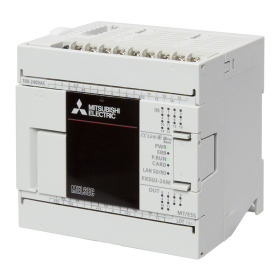
FX5UJ CPU module Name Description DIN rail mounting hook Hook for mounting a CPU module on a DIN rail of DIN46277 (width: 35mm). Expansion adapter connecting hooks When connecting an expansion adapter, secure it with these hooks. Terminal block cover Cover for protecting the terminal block. - Page 68 With the cover open [10] [10] Name Description Built-in Ethernet communication Connector for connection with Ethernet-compatible devices. For details, refer to MELSEC iQ-F FX5 User's Manual (Ethernet Communication). connector RUN/STOP/RESET switch Switch for operating the CPU module. RUN: Runs the program STOP: Stops the program RESET: Resets the CPU module (Hold the switch on the RESET side for approximately 1 second.) SD memory card disable switch...
- Page 69 Left side/Right side Left side Right side Name Description Expansion adapter connector cover Cover for protecting the expansion adapter connector. Connect the expansion adapter to the expansion adapter connector under the cover. Genuine product certification label Genuine product certification label to prevent counterfeiting Nameplate The product model name, manufacturer's serial number, power supply specifications, and MAC address are shown.
-
Page 70: Fx5U Cpu Module
FX5U CPU module [10] [11] Name Description DIN rail mounting hook Hook for mounting a CPU module on a DIN rail of DIN46277 (width: 35mm). Expansion adapter connecting hooks When connecting an expansion adapter, secure it with these hooks. Terminal block cover Cover for protecting the terminal block. - Page 71 With the cover open [12] [13] [10] [11] [13] [12] Name Description Built-in RS-485 communication Terminal block for connection with RS-485-compatible devices terminal block RS-485 terminal resistor selector Switch for switching terminal resistance for built-in RS-485 communications. switch RUN/STOP/RESET switch Switch for operating the CPU module.
- Page 72 Left side/Right side Left side Right side Name Description Expansion adapter connector cover Cover for protecting the expansion adapter connector. Connect the expansion adapter to the expansion adapter connector under the cover. Genuine product certification label Genuine product certification label to prevent counterfeiting Nameplate The product model name, manufacturer's serial number, power supply specifications, and MAC address are shown.
-
Page 73: Fx5Uc Cpu Module
FX5UC CPU module Connector type Spring clamp terminal With cover open block type [11] [17] [16] [12] [15] [13] [10] [14] Name Description Expansion adapter connecting hooks When connecting an expansion adapter, secure it with these hooks. Built-in RS-485 communication Terminal block for connection with RS-485-compatible devices terminal block Built-in Ethernet communication... - Page 74 Name Description [12] Input display LED Turns on when input is on. [13] Output display LED Turns on when output is on. [14] Output terminal Terminals for output. For details on the terminal layout, refer to Page 101 Power, input/output terminal block. [15] SD memory card disable switch Switch for disabling access to the SD memory card when the SD memory card is to be removed.
- Page 75 Top side/Bottom side Name Description Battery cover Cover for protecting the battery connecting connector. Power connector for CPU module Connector for connecting power cables. RS-485 terminal resistor selector Switch for switching terminal resistance for built-in RS-485 communications. switch Terminal names shows a function grounding terminal.
-
Page 76: I/O Module
I/O Module This section describes the part names of the I/O modules. Input module, output module, I/O module Extension cable type With the cover removed 2-4.5 mounting hole (Unit: mm) Name Description Input display LED, Output display LED Turns on when input or output is on. POWER LED Indicates whether the input modules/output modules are powered or not. - Page 77 Extension connector type ■Input/output connection type: Connector (Unit: mm) Name Description Extension connector Connector connected to extend modules PWR/POWER LED Indicates whether the input modules/output modules are powered or not. On: Powered Off: Not powered or hardware error I/O display LED Turns on when input or output is on.
-
Page 78: Powered Input/Output Module
Powered input/output module 2-4.5 mounting hole 140 (mounting hole pitch) With the cover removed [10] (Unit: mm) Name Description Extension connector cover (for Cover for protecting the extension connector cover (for preceding module). preceding module) Terminal block cover Cover for protecting the terminal block. The cover can be opened for wiring. -
Page 79: High-Speed Pulse Input/Output Module
High-speed pulse input/output module With the cover removed 2-4.5 mounting hole (Unit: mm) Name Description Input display LED, Output display LED Turns on when input or output is on. POWER LED Indicates whether the input modules/output modules are powered or not. Powered Off: Not powered or hardware error Pullout tab... -
Page 80: Extension Power Supply Module
Extension Power Supply Module This section describes the part names of the extension power supply module. Extension cable type With the top cover removed Name Description POWER LED Indicates whether the input modules/output modules are powered or not. On: Powered Off: Not powered or hardware error Top cover Cover for protecting the extension connector and power terminal block. - Page 81 Extension connector type [12] [10] [11] Name Description Extension connector (for preceding module) Connector for connecting the supplied extension cable that connects to the preceding module (the CPU module side). POWER LED Indicates whether the input modules/output modules are powered or not. On: Powered Off: Not powered or hardware error Extension connector cover...
-
Page 82: Connector Conversion Module
Connector Conversion Module This section describes the part names of the connector conversion module. FX5-CNV-IF (Unit: mm) Name Description Extension connector (for preceding Connector for connecting the supplied extension cable that connects to the preceding module (the CPU module) module side). Extension connector Connector for connecting the extension connector of an extension module (extension connector type). -
Page 83: Sd Memory Card Module
SD Memory Card Module This section describes the part names of the SD memory card module. When the module is used with a communication board, cut this area off. 43.6 11.6 Name Operation status display LED Green Turns on when the SD memory card can be used or cannot be removed. (CARD LED) Flashing when in preparation. -
Page 84: Chapter 4 General Specifications
GENERAL SPECIFICATIONS This chapter describes the common specifications for the modules to be used. Item Specifications Operating FX5S CPU module 0 to 55, non-freezing ambient FX5UJ CPU module temperature *2*3 FX5U CPU module -20 to 55, non-freezing FX5UC CPU module Storage ambient temperature -25 to 75, non-freezing Operating ambient humidity... - Page 85 Dielectric withstand voltage test and insulation resistance test Perform dielectric withstand voltage test and insulation resistance test at the following voltages between each terminal and the CPU module ground terminal. ■CPU module, I/O module Between terminals Dielectric withstand voltage Insulation resistance FX5S FX5UJ FX5U...
-
Page 86: Chapter 5 Cpu Module Performance Specifications
CPU MODULE PERFORMANCE SPECIFICATIONS CPU and Memory Specifications This sections describes the performance specifications of the CPU module. Item Specifications FX5S FX5UJ FX5U FX5UC Control Method Stored-program repetitive operation Input/output control system Refresh system (Direct access input/output allowed by specification of direct access input/output (DX, DY)) Programming Programming language Ladder diagram (LD), structured text (ST), function... - Page 87 *1 For supported versions, refer to the following. MELSEC iQ-F FX5 User's Manual (Application) *2 Interrupt from the intelligent function module and high-speed pulse input/output module. *3 When the program capacity is 64k steps. *4 The value listed above indicates the number of files stored in the root folder. *5 Clock data is retained using the power accumulated in a large-capacity capacitor incorporated into the programmable controller.
-
Page 88: Number Of Device Points
Number of device points Item Base Maximum number of points FX5S FX5UJ FX5U FX5UC Number of user device Input relay (X) 1024 points points Output relay (Y) 1024 points Internal relay (M) 32768 points 7680 points 32768 points Latch relay (L) 32768 points 7680 points 32768 points... -
Page 89: Power Supply Specifications
Power Supply Specifications This sections describes the power supply specifications of the CPU module. AC power supply Item Specifications FX5S FX5UJ FX5U Rated voltage 100 to 240VAC Voltage fluctuation range -15%, +10% Rated frequency 50/60Hz Allowable instantaneous power failure time Operation can be continued upon Operation can be continued upon occurrence of instantaneous power occurrence of instantaneous... - Page 90 The following shows the power failure detection period of the AC power supply. (FX5UJ/FX5U CPU modules only) AC power supply (AC detection) Approx. 3ms SM8000 RUN monitor 1 scan time SM8007 momentary power failure detection SM8008 power failure detected SD8008 Power failure detection period 10 to 13ms...
-
Page 91: Dc Power Supply
DC power supply Item Specifications FX5U FX5UC Rated voltage 24VDC Voltage fluctuation range -30%, +20% +20%, -15% Allowable instantaneous power Operation can be continued upon occurrence of instantaneous power failure for 5ms or less. failure time Power fuse FX5U-32M: 250V 3.15A Time-lag fuse 125V, 3.15A Time-lag fuse FX5U-64M, FX5U-80M: 250V 5A Time-lag fuse Rush current... -
Page 92: Input Specifications
Input Specifications This section describes the input specifications of the CPU module. Item Specifications FX5S FX5UJ FX5U FX5UC Number of Input Points FX5S-30M: 16 points FX5UJ-24M: 14 points FX5U-32M: 16 points FX5UC-32M: 16 points FX5S-40M: 24 points FX5UJ-40M: 24 points FX5U-64M: 32 points FX5UC-64M: 32 points FX5S-60M: 36 points... - Page 93 Item Specifications FX5S FX5UJ FX5U FX5UC Input response time • X0, X1, X3, X4 FX5U-32M: FX5UC-32M: (Delay time of the hardware filter) On: 5s or less • X0 to X5 • X0 to X5 Off: 5s or less On: 2.5s or less On: 2.5s or less •...
- Page 94 • FX5S CPU module, FX5UJ CPU module, and FX5U CPU module circuit configuration Item Circuit configuration diagram Sink input wiring Source input wiring AC power supply When using 24VDC service Fuse Fuse power supply 100 to 240VAC 100 to 240VAC Input impedance Input impedance When using external power...
- Page 95 • FX5UC CPU module circuit configuration Item Circuit configuration diagram Sink input wiring Source input wiring FX5UC-MT/D Fuse 24VDC Photocoupler Input impedance FX5UC-M/DS Fuse Photocoupler Photocoupler Fuse 24VDC 24VDC COM0 COM0 Input impedance Input impedance For the spring clamp terminal block type, For the spring clamp terminal block type, the [COM0] terminal is the [S/S] terminal.
-
Page 96: Output Specifications
Output Specifications This sections describes the output specifications of the CPU module. Relay output Item Output specifications FX5S FX5UJ FX5U FX5UC Number of Output Points FX5S-30MR: 14 points FX5UJ-24MR: 10 points FX5U-32MR: 16 points FX5UC-32MR/DS-TS: 16 FX5S-40MR: 16 points FX5UJ-40MR: 16 points FX5U-64MR: 32 points points FX5S-60MR: 24 points... - Page 97 • FX5UC CPU module circuit configuration Item Circuit configuration diagram Relay output Load DC power supply COM Fuse COM Load AC power supply COM Fuse COM A common number is inserted into of [COM 5 CPU MODULE PERFORMANCE SPECIFICATIONS 5.4 Output Specifications...
- Page 98 Transistor output Item Output specifications FX5S FX5UJ FX5U FX5UC Number of Output Points FX5S-30MT: 14 points FX5UJ-24MT: 10 points FX5U-32MT: 16 points FX5UC-32MT: 16 points FX5S-40MT: 16 points FX5UJ-40MT: 16 points FX5U-64MT: 32 points FX5UC-64MT: 32 points FX5S-60MT: 24 points FX5UJ-60MT: 24 points FX5U-80MT: 40 points FX5UC-96MT: 48 points...
- Page 99 • FX5S CPU module, FX5UJ CPU module, and FX5U CPU module circuit configuration Item Circuit configuration diagram Sink output wiring Source output wiring Transistor output Load Load DC power supply DC power supply COM +V Fuse Fuse A common number is inserted into of [COM]. A common number is inserted into ...
-
Page 100: Input/Output Derating Curve
Input/Output Derating Curve The derating curve below shows the simultaneous ON ratio of available programmable controller inputs or outputs with respect to the ambient temperature. Use the programmable controller within the simultaneous input or output ON ratio range shown in the figure. FX5S CPU module For the FX5S CPU module, derating is available for relay output type only. -
Page 101: Built-In Analog Specifications
FX5UC CPU module Derating chart Simultaneous ON ratio Power supply voltage: 24VDC Single module (CPU module only) 100% Expanded Available -20 25 40 55 Ambient temperature Built-in Analog Specifications Refer to the following. MELSEC iQ-F FX5 User's Manual (Analog Control - CPU module built-in, Expansion adapter) Positioning Specifications Refer to the following. -
Page 102: Terminal Layout
Terminal Layout Built-in analog terminal European-type terminal block 5 poles Analog Analog input output Built-in Ethernet connector Signal name TXD+ TXD- RXD+ Not used Not used RXD- Not used Not used Built-in RS-485 terminal European-type terminal block • FX5U CPU module, FX5UJ CPU module 5 poles •... -
Page 103: Power, Input/Output Terminal Block
Power, input/output terminal block • Interpretation of terminal block layout FX5U CPU module Power supply 24 V DC service Vacant terminal terminals power supply Input terminal (Do not use this terminal.) S/S 0V Output terminals FX5U-32MR/ES connected to COM3 COM0 COM1 COM2 COM3... - Page 104 AC power supply • FX5S CPU module Model Terminal layout FX5S-30MR/ES, FX5S-30MT/ES 12 Y13 COM1 COM0 COM2 COM3 FX5S-30MT/ESS 12 Y13 FX5S-40MR/ES, FX5S-40MT/ES COM0 COM1 COM2 COM3 FX5S-40MT/ESS FX5S-60MR/ES, FX5S-60MT/ES COM0 COM1 COM2 COM3 COM4 COM5 FX5S-60MT/ESS 5 CPU MODULE PERFORMANCE SPECIFICATIONS 5.9 Terminal Layout...
- Page 105 Model Terminal layout FX5S-80MR/ES 21 23 25 31 33 35 37 41 43 45 47 51 53 55 57 FX5S-80MT/ES 34 36 44 46 54 56 COM0 COM1 COM2 COM3 COM4 COM5 COM6 COM7 FX5S-80MT/ESS 21 23 25 31 33 35 37 41 43 45 47 51 53...
- Page 106 • FX5UJ CPU module Model Terminal layout FX5UJ-24MR/ES, S/S 1 FX5UJ-24MT/ES COM0 COM1 COM2 FX5UJ-24MT/ESS S/S 1 1 +V1 FX5UJ-40MR/ES, FX5UJ-40MT/ES COM0 COM1 COM2 COM3 FX5UJ-40MT/ESS Y14 16 FX5UJ-60MR/ES, FX5UJ-60MT/ES 36 X40 Y10 12 Y14 16 Y24 26 COM0 COM1 COM2 COM3 COM4...
- Page 107 • FX5U CPU module Model Terminal layout FX5U-32MR/ES S/S 0V FX5U-32MT/ES COM0 COM1 COM2 COM3 FX5U-32MT/ESS S/S 0V FX5U-64MR/ES S/S 0V 16 X20 FX5U-64MT/ES COM5 COM0 COM1 COM2 COM3 COM4 FX5U-64MT/ESS S/S 0V 16 X20 FX5U-80MR/ES S/S 0V X40 42 FX5U-80MT/ES COM0 COM1...
- Page 108 DC power supply • FX5U CPU module Model Terminal layout FX5U-32MR/DS FX5U-32MT/DS COM0 COM1 COM2 COM3 FX5U-32MT/DSS FX5U-64MR/DS, FX5U-64MT/DS COM5 COM0 COM1 COM2 COM3 COM4 FX5U-64MT/DSS 16 X20 FX5U-80MR/DS X40 42 FX5U-80MT/DS COM0 COM1 COM2 COM3 COM4 COM5 COM6 FX5U-80MT/DSS X40 42 5 CPU MODULE PERFORMANCE SPECIFICATIONS 5.9 Terminal Layout...
- Page 109 ■I/O connector • FX5UC CPU module FX5UC-32MT/D FX5UC-32MT/DSS FX5UC-64MT/D FX5UC-64MT/DSS Input Input Input Input Input Input Notched Notched Notched Notched edge edge edge edge COM0 COM0 COM0 COM0 COM1 COM1 Output Output Output Output Output Output Notched Notched Notched Notched edge edge edge...
- Page 110 ■I/O terminal block • FX5UC CPU module FX5UC-32MT/DS-TS FX5UC-32MT/DSS-TS FX5UC-32MR/DS-TS Input Input Input Input S/S0 S/S0 S/S1 S/S1 Output Output Output Output COM0 COM0 COM1 COM1 COM0 COM0 *1 Terminals with the same name (for example, X0 and X0, Y0 and Y0) are internally connected. ■Terminal block •...
-
Page 111: External Dimensions
5.10 External Dimensions FX5S CPU module ■FX5S-30M, FX5S-40M, FX5S-60M 2-4.5 mounting hole (Unit: mm) Model W1 (mounting hole pitch) Mass (weight) FX5S-30MR/ES 100mm 81mm Approx. 0.45kg FX5S-30MT/ES FX5S-30MT/ESS FX5S-40MR/ES 130mm 111mm Approx. 0.55kg FX5S-40MT/ES FX5S-40MT/ESS FX5S-60MR/ES 175mm 156mm Approx. 0.65kg FX5S-60MT/ES FX5S-60MT/ESS ■FX5S-80M... - Page 112 ■With an expansion board installed For FX5-SDCD 15.1 71.4 (87) (Unit: mm) For FX5-SDCD and FX5-485-BD (30.5) 71.4 (101.9) (Unit: mm) 5 CPU MODULE PERFORMANCE SPECIFICATIONS 5.10 External Dimensions...
- Page 113 FX5UJ CPU module 2-4.5 mounting hole (Unit: mm) Model W1 (mounting hole pitch) Mass (weight) FX5UJ-24MR/ES 95mm 76mm Approx. 0.55kg FX5UJ-24MT/ES FX5UJ-24MT/ESS FX5UJ-40MR/ES 130mm 111mm Approx. 0.65kg FX5UJ-40MT/ES FX5UJ-40MT/ESS FX5UJ-60MR/ES 175mm 156mm Approx. 0.80kg FX5UJ-60MT/ES FX5UJ-60MT/ESS ■With an expansion board installed For FX5-485-BD (30.5) 71.4...
- Page 114 FX5U CPU module ■FX5U-32M 2-4.5 mounting hole (Unit: mm) Model W1 (mounting hole pitch) Mass (weight) FX5U-32MR/ES 150mm 123mm Approx. 0.7kg FX5U-32MT/ES FX5U-32MT/ESS FX5U-32MR/DS FX5U-32MT/DS FX5U-32MT/DSS ■FX5U-64M, FX5U-80M 4-4.5 mounting hole (Unit: mm) Model W1 (mounting hole pitch) Mass (weight) FX5U-64MR/ES 220mm 193mm...
- Page 115 ■With an expansion board installed For FX5-485-BD (30.5) 71.4 (101.9) (Unit: mm) 5 CPU MODULE PERFORMANCE SPECIFICATIONS 5.10 External Dimensions...
- Page 116 FX5UC CPU module ■Connector type 89.1 (Unit: mm) Model Mass (weight) FX5UC-32MT/D 42.1mm Approx. 0.2kg FX5UC-32MT/DSS FX5UC-64MT/D 62.2mm Approx. 0.3kg FX5UC-64MT/DSS FX5UC-96MT/D 82.3mm Approx. 0.35kg FX5UC-96MT/DSS ■Spring clamp terminal block type 93.7 (Unit: mm) Model Mass (weight) FX5UC-32MT/DS-TS 48.1mm Approx. 0.25kg FX5UC-32MT/DSS-TS FX5UC-32MR/DS-TS 68.2mm...
-
Page 117: Chapter 6 I/O Module Performance Specifications
I/O MODULE PERFORMANCE SPECIFICATIONS This chapter describes the performance specifications of the I/O module. There is the simultaneous ON ratio of available programmable controller inputs or outputs with respect to the ambient temperature. For details, refer to the following. Page 98 Input/Output Derating Curve *1 For extension cable type I/O modules, refer to the derating for the connected CPU module. - Page 118 • Circuit configuration Item Circuit configuration diagram Sink input wiring Source input wiring When using external power supply CPU module CPU module 24VDC 24VDC Input module Input module When using 24VDC service power supply CPU module CPU module Input module Input module Terminal layout FX5-8EX/ES...
-
Page 119: Extension Connector Type
Extension connector type Item Specifications FX5-C16EX/D FX5-C16EX/DS FX5-C32EX/D FX5-C32EX/DS FX5-C32EX/DS-TS Current 5VDC 100mA 100mA 120mA 120mA 120mA consumption 24VDC 65mA (0mA 65mA (0mA 130mA (0mA 130mA (0mA 130mA (0mA Mass (weight) Approx. 0.1kg Approx. 0.1kg Approx. 0.15kg Approx. 0.15kg Approx. 0.15kg External color Munsell 0.6B7.6/0.2 ■Input specifications... - Page 120 • Circuit configuration Item Circuit configuration diagram Sink input wiring Source input wiring When using external power FX5-C16EX/D 24VDC Photocoupler supply FX5-C32EX/D FX5-C16EX/DS 24VDC 24VDC Photocoupler FX5-C32EX/DS Photocoupler FX5-C32EX/DS-TS CPU module CPU module 24VDC 24VDC Input module Input module When using 24VDC service FX5-C16EX/DS CPU module...
-
Page 121: Output Module
Output Module Extension cable type Item Specifications FX5-8EYR/ES FX5-16EYR/ES FX5-8EYT/ES FX5-16EYT/ES FX5-8EYT/ESS FX5-16EYT/ESS Current 5VDC 75mA 100mA 75mA 100mA 75mA 100mA consumption 24VDC 75mA 125mA 75mA 125mA 75mA 125mA Mass (weight) Approx. 0.2kg Approx. 0.25kg Approx. 0.2kg Approx. 0.25kg Approx. 0.2kg Approx. - Page 122 Terminal layout FX5-8EYR/ES FX5-16EYR/ES FX5-8EYT/ESS FX5-16EYT/ESS FX5-8EYT/ES FX5-16EYT/ES Lower Lower number number Higher Higher number number 6 I/O MODULE PERFORMANCE SPECIFICATIONS 6.2 Output Module...
-
Page 123: Extension Connector Type
Extension connector type Item Specifications FX5-C16EYR/D- FX5- FX5- FX5- FX5- FX5- FX5- C16EYT/D C32EYT/D C32EYT/D- C16EYT/ C32EYT/ C32EYT/ DSS-TS Current 5VDC 100mA 100mA 120mA 120mA 100mA 120mA 120mA consumption 24VDC 100mA 100mA 200mA 200mA 100mA 200mA 200mA Mass (weight) Approx. 0.2kg Approx. - Page 124 Terminal layout FX5-C16EYR/D-TS FX5-C16EYT/D FX5-C16EYT/DSS Output Output Output Notched Notched edge edge COM0 COM0 COM0 COM0 Output COM1 COM1 FX5-C32EYT/D FX5-C32EYT/D-TS FX5-C32EYT/DSS FX5-C32EYT/DSS-TS Output Output Output Output Notched Notched Lower Lower edge edge number number COM0 COM0 COM0 COM0 Output Output Output Output...
-
Page 125: I/O Module
I/O Module Extension cable type Item Specifications FX5-16ER/ES FX5-16ET/ES FX5-16ET/ESS Current 5VDC 100mA consumption 24VDC 125mA (85mA Mass (weight) Approx. 0.25kg External color Munsell 0.6B7.6/0.2 ■Input specifications Number of input points 8 points Connection type Screw terminal block (M3 screws) Input type Sink/source Input signal voltage... - Page 126 • Input circuit configuration Item Circuit configuration diagram Sink input wiring Source input wiring When using external power supply CPU module CPU module 24VDC 24VDC Input module Input module When using 24VDC service power CPU module CPU module supply Input module Input module •...
- Page 127 Terminal layout FX5-16ER/ES FX5-16ET/ESS FX5-16ET/ES 6 I/O MODULE PERFORMANCE SPECIFICATIONS 6.3 I/O Module...
-
Page 128: Extension Connector Type
Extension connector type Item Specifications FX5-C32ET/D FX5-C32ET/DS-TS FX5-C32ET/DSS FX5-C32ET/DSS-TS Current 5VDC 120mA consumption 24VDC 165mA (100mA Mass (weight) Approx. 0.25kg Approx. 0.15kg External color Munsell 0.6B7.6/0.2 ■Input specifications Number of input points 16 points Connection type Connector Spring clamp terminal block Connector Spring clamp terminal block Input type... - Page 129 • Input circuit configuration Item Circuit configuration diagram Sink input wiring Source input wiring When using external power FX5-C32ET/D 24VDC Photocoupler supply FX5-C32ET/DSS 24VDC 24VDC Photocoupler Photocoupler FX5-C32ET/DS-TS, CPU module CPU module FX5-C32ET/DSS-TS 24VDC 24VDC Input module Input module When using 24VDC service FX5-C32ET/DSS, CPU module...
- Page 130 Terminal layout FX5-C32ET/D FX5-C32ET/DS-TS FX5-C32ET/DSS FX5-C32ET/DSS-TS Input Input Input Input Notched Notched edge edge COM0 COM0 Output Output Output Output COM0 COM0 COM0 COM0 6 I/O MODULE PERFORMANCE SPECIFICATIONS 6.3 I/O Module...
-
Page 131: Powered I/O Module
Powered I/O Module Extension cable type Item Specifications FX5-32ER/ES FX5-32ET/ES FX5-32ET/ESS FX5-32ER/DS FX5-32ET/DS FX5-32ET/DSS Mass (weight) Approx. 0.65kg External color Munsell 0.6B7.6/0.2 ■Power supply specifications Rated voltage 100 to 240VAC 24VDC Voltage fluctuation range -15%, +10% -30%, +20% Rated frequency 50/60Hz Allowable instantaneous power Operation can be continued upon occurrence of... - Page 132 Item Specifications FX5-32ER/ES FX5-32ET/ES FX5-32ET/ESS FX5-32ER/DS FX5-32ET/DS FX5-32ET/DSS External power supply 30VDC or less 5-30VDC 30VDC or less 5-30VDC 240VAC or less 240VAC or less Indication of output operation LED turns on when output is on. Max. load 2A/point 0.5A/point 2A/point 0.5A/point The total load...
- Page 133 • Output circuit configuration Item Circuit configuration diagram Relay output Load DC power supply COM0 Fuse AC power supply COM1 Fuse Item Circuit configuration diagram Sink output wiring Source output wiring Transistor output Load Load DC power supply DC power supply COM0 Fuse Fuse...
-
Page 134: High-Speed Pulse Input/Output Module
High-Speed Pulse Input/Output Module Extension cable type Item Specifications FX5-16ET/ES-H FX5-16ET/ESS-H Current 5VDC 100mA consumption 24VDC 125mA (85mA Mass (weight) Approx. 0.25kg External color Munsell 0.6B7.6/0.2 ■Input specifications Number of input points 8 points Connection type Screw terminal block (M3 screws) Input type Sink/source Input signal voltage... - Page 135 • Input circuit configuration Item Circuit configuration diagram Sink input wiring Source input wiring When using external power supply CPU module CPU module 24VDC 24VDC Input module Input module When using 24VDC service power CPU module CPU module supply Input module Input module •...
-
Page 136: External Dimensions
External Dimensions Extension cable type With the cover removed 2-4.5 mounting hole (Unit: mm) Product Model Input module FX5-8EX/ES, FX5-16EX/ES 40mm Output module FX5-8EYR/ES, FX5-8EYT/ES, FX5-8EYT/ESS, 40mm FX5-16EYR/ES, FX5-16EYT/ES, FX5-16EYT/ESS I/O module FX5-16ER/ES, FX5-16ET/ES, FX5-16ET/ESS 40mm High-speed pulse input/output module FX5-16ET/ES-H, FX5-16ET/ESS-H 40mm 6 I/O MODULE PERFORMANCE SPECIFICATIONS... - Page 137 Extension connector type ■Input/output connection type: Connector (Unit: mm) Product Model Input module FX5-C16EX/D, FX5-C16EX/DS 14.6mm FX5-C32EX/D, FX5-C32EX/DS 20.1mm Output module FX5-C16EYT/D, FX5-C16EYT/DSS 14.6mm FX5-C32EYT/D, FX5-C32EYT/DSS 20.1mm I/O module FX5-C32ET/D, FX5-C32ET/DSS 20.1mm ■Input/output connection type: Spring clamp terminal block 19.7 (Unit: mm) Product Model...
- Page 138 Powered input/output module 2-4.5 mounting hole 140 (mounting hole pitch) (Unit: mm) Product Model Powered input/output module FX5-32ER/ES, FX5-32ET/ES, FX5-32ET/ESS, 150mm FX5-32ER/DS, FX5-32ET/DS, FX5-32ET/DSS 6 I/O MODULE PERFORMANCE SPECIFICATIONS 6.6 External Dimensions...
-
Page 139: Chapter 7 Extension Power Supply Module Performance Specifications
EXTENSION POWER SUPPLY MODULE PERFORMANCE SPECIFICATIONS This chapter describes the performance specifications of the extension power supply module. Performance Specifications Item Specifications FX5-1PSU-5V FX5-C1PS-5V Rated voltage 100 to 240VAC 24VDC Voltage fluctuation range -15%, +10% +20%, -15% Rated frequency 50/60Hz ... -
Page 140: External Dimensions
External Dimensions Extension cable type 2-4.5 mounting hole (Unit: mm) Product Model Extension power supply module FX5-1PSU-5V Extension connector type 20.1 (Unit: mm) Product Model Extension power supply module FX5-C1PS-5V 7 EXTENSION POWER SUPPLY MODULE PERFORMANCE SPECIFICATIONS 7.2 External Dimensions... -
Page 141: Chapter 8 Connector Conversion Module Performance Specifications
CONNECTOR CONVERSION MODULE PERFORMANCE SPECIFICATIONS This chapter describes the performance specifications of the connector conversion module. Specifications Item Specifications FX5-CNV-IF FX5-CNV-IFC External color Munsell 0.6B7.6/0.2 Munsell 0.6B7.6/0.2 Mass (weight) Approx. 60g Approx. 60g External Dimensions FX5-CNV-IF FX5-CNV-IFC (Unit: mm) Product Model Connector conversion module FX5-CNV-IF... - Page 142 MEMO 8 CONNECTOR CONVERSION MODULE PERFORMANCE SPECIFICATIONS 8.2 External Dimensions...
-
Page 143: Chapter 9 Sd Memory Card Performance Specifications
• Operational compatibility of the SD memory cards manufactured by Mitsubishi Electric (NZ1MEM-GBSD) with MELSEC iQ-F series CPU modules has been checked. Use of SD memory card other than a Mitsubishi Electric SD memory card may result in loss of the data stored in the SD memory card, or problems such as system stop. - Page 144 MEMO 9 SD MEMORY CARD PERFORMANCE SPECIFICATIONS 9.2 Formatting...
-
Page 145: Chapter 10 Battery Performance Specifications
BATTERY PERFORMANCE SPECIFICATIONS. The following shows functional specifications of the battery. The battery can be connected to the FX5U/FX5UC CPU modules. Item FX3U-32BL Battery type Lithium manganese dioxide battery Nominal voltage 3.0V Life Standard life: 5 years (at ambient temperature of 25) *1 The life of the battery changes with respect to ambient temperature. - Page 146 MEMO 10 BATTERY PERFORMANCE SPECIFICATIONS. 10.2 Battery Life...
-
Page 147: Chapter 11 Function List
FUNCTION LIST The following table lists the functions of the CPU module. : Supported, : Limitedly supported, : Not supported For details, refer to MELSEC iQ-F FX5 User's Manual (Application). Function Description Availability FX5S FX5UJ FX5U FX5UC Firmware update function Updates the module's firmware version. - Page 148 Function Description Availability FX5S FX5UJ FX5U FX5UC Data backup/restoration function Backs up program files, parameter files, and device/label data files in a CPU module to an SD memory card. The backup data can be restored as needed. ...
-
Page 149: Chapter 12 Installation
INSTALLATION 12.1 Installation Positions Use the programmable controller under the environmental conditions complying with the general specifications. ( Page 82 GENERAL SPECIFICATIONS) Installation positions in a control panel To prevent temperature rise, do not mount the programmable controller on the floor or ceiling, or in the vertical direction. Always mount the programmable controller horizontally on the wall as shown in the following figure. -
Page 150: Layout In Control Panel
Layout in control panel The programmable controller components can be laid out in one stage or in two stages (upper and lower).The connecting procedures in each case are explained below. Extension devices can be connected on the left and right sides of the CPU module of the programmable controller. (For the FX5S CPU module, extension devices can be connected on the left of the CPU module located in the middle.) Keep a space of at least 50mm between the module main body or other devices and structure. -
Page 151: Installation Methods
12.2 Installation Methods This section describes the installation methods. There are three installation methods as listed in the following table. Installation methods FX5S FX5UJ FX5U FX5UC Installing on DIN rail Installing directly Example of combination of installation on ... -
Page 152: Preparation For Installation
Example of combination of installation on DIN rail and direct installation • The CPU module side can be installed on the DIN rail, and the extension modules extended by the extended extension cable can be directly installed. • The programmable controller can be installed on a 35mm wide DIN46277 rail. •... -
Page 153: Installing On Din Rail
Installing on DIN rail A module can be installed on a 35mm wide DIN46277 rail. Installation Push out all DIN rail mounting hooks (A in the figure). Fit the upper edge of the DIN rail mounting groove (B in the figure) onto the DIN rail. Lock the DIN rail mounting hooks (C in the figure) while pressing the module against the DIN rail. -
Page 154: Installing Directly
Installing directly The module can be installed directly in the control panel. Mounting hole pitch Position the holes so that there is a gap of about 2mm between the products. FX5- FX5U-32MT/ES FX5- FX5-1PSU-5V FX5- FX3U- 16EX/ES CNV- 15.1 (Unit: mm) For details on the mounting hole pitches for each module, refer to the external dimensions. - Page 155 Installation of extension module (extension cable type) Make mounting holes on the mounting surface Back side Back side according to the external dimensions diagram. Push in the DIN rail mounting hook (A in the figure) of the extension module (extension cable type). When the DIN rail mounting hook is not pushed in, the screw hole is covered, and the extension module cannot be mounted.
-
Page 156: Method For Connection Of Extension Devices
12.3 Method for Connection of Extension Devices Connection of an expansion board (communication board) FX5S FX5UJ FX5U FX5UC This section describes how to connect the expansion board (communication board) to the CPU module. Remove the expansion board connector cover from the Expansion board connector cover front face of the CPU module. -
Page 157: Connection Of An Expansion Board (Sd Memory Card Module)
Connection of an expansion board (SD memory card module) FX5S FX5UJ FX5U FX5UC An SD memory card module can be connected to the FX5S CPU module only. Do not connect an SD memory card module to a module other than the FX5S CPU module. Otherwise, it may cause damage or malfunction. -
Page 158: Connection Of An Expansion Adapter
Connection of an expansion adapter FX5S FX5UJ FX5U FX5UC This subsection describes how to connect the expansion adapter to the CPU module. Remove the expansion adapter connector cover (A in the right figure). Slide the hook for coupling the expansion adapter of the CPU module (B in the figure). -
Page 159: Connection Of An Extension Module (Extension Cable Type)
Connection of an extension module (extension cable type) FX5S FX5UJ FX5U FX5UC This subsection describes how to connect an extension module (extension cable type). A connector conversion module is required to connect an extension cable type module to an FX5UC CPU module system. Precautions •... -
Page 160: Connection Of An Extension Module (Extension Connector Type)
Connection of an extension module (extension connector type) FX5S FX5UJ FX5U FX5UC This subsection describes how to connect the extension module (extension connector type). A connector conversion module is required to connect an extension connector type module to an FX5UJ CPU module system and an FX5U CPU module system. -
Page 161: Connection Of An Extended Extension Cable And Connector Conversion Adapter
Connection of an extended extension cable and connector conversion adapter FX5S FX5UJ FX5U FX5UC This subsection describes the procedures for connecting an extended extension cable and the FX5-CNV-BC to the extension cable of the FX5 extension module. Separate the case of the connector conversion adapter into two halves as shown in the figure. -
Page 162: Chapter 13 Wiring
WIRING 13.1 Wiring Procedure Before wiring, turn off the source power supply. Procedure Item Description Reference Page 161 Preparation of Wiring Components Preparation of wiring Prepare crimp terminals and cables needed for wiring. components In addition, check the terminal processing and cable connecting procedures, such as cable installation and disconnection. -
Page 163: Preparation Of Wiring Components
13.2 Preparation of Wiring Components This section describes the wiring components to be prepared. Power cables This subsection describes the procedure for connecting power cables for the FX5UC CPU module, extension power supply module, and I/O module. Power cables The power must be supplied to the FX5UC CPU module, the FX5-C1PS-5V, the FX5-CEX/D, and the FX5-C32ET/D. The power is supplied to the FX5UC CPU module and the FX5-C1PS-5V using cables for the CPU module and extension power supply module. -
Page 164: Connector
■Suitable connector (commercially available connector) Use 20-pin (1-key) sockets conforming to MIL-C-83503. Check that the sockets do not interfere with peripheral parts including connector covers in advance. ■I/O cables (Mitsubishi Electric option) I/O cables on which connectors are attached are prepared. Model... - Page 165 ■Connectors for self-making I/O cables (Mitsubishi Electric option) Prepare wires and crimp tools by users. Model and configuration of I/O connectors Suitable wiring (UL-1061-compliant products are recommended) and tool Mitsubishi Electric model Part description Wire size Crimp tool (Manufactured by DDK Ltd.) (Manufactured by DDK Ltd.)
-
Page 166: Screw Terminal Block
Screw terminal block Wire the screw terminal block in accordance with the following specifications. Terminal screw size and tightening torque Screw location Screw size Tightening torque CPU module Terminal block screw 0.5 to 0.8Nm Terminal block mounting screws 0.4 to 0.5Nm I/O module Terminal block screw 0.5 to 0.8Nm... - Page 167 ■M3.5 terminal screw • When a single wire is connected to a single terminal 3.7 Terminal Solderless screw terminal 6.8mm or less 3.7 6.8mm Terminal or less • When two wires are connected to a single terminal 3.7 Terminal Solderless 6.8mm screw terminal...
-
Page 168: European-Type Terminal Block
■Installation Place the terminal block at its predetermined position and tighten the terminal block mounting screws on the left and right sides uniformly. Note that there is no gap between the terminal block and mount position. Precautions Do not tighten the terminal block mounting screws with torque exceeding the specified range. Doing so may cause failures or malfunctions. - Page 169 Wire end treatment Treat stranded and solid wires as they are or use wire ferrules with insulation sleeves for wiring terminals. ■When stranded and solid wires are treated as they are • Twist the end of stranded wires, and make sure that there are no loose wires. •...
-
Page 170: Spring Clamp Terminal Block
Spring clamp terminal block Wire the spring clamp terminal block in accordance with the following specifications. For information regarding spring clamp terminal blocks for intelligent function modules and FX5 safety extension modules, refer to the user's manuals for each module. Suitable wiring The wires to connect the spring clamp terminal block are described below. - Page 171 Removing and installing the terminal block Follow the below procedures to remove and install the terminal block. ■Lever position to lock and release A 3-step stopper is attached to prevent the lever from rotating, facilitating installation and removal of the terminal block. When removing or installing the terminal block, move the lever to the corresponding position.
- Page 172 Connection and disconnection of the cable Spring clamp terminal block is the push-in type, therefore, wiring without a tool is possible by simply inserting the connecting terminal to the terminal block. However, the push-in type does not support stranded wire, and a tool is required for connecting cables. ■Connection of the cable Fully insert a cable or bar solderless, terminal whose end has been properly processed, into the wire insertion opening.
-
Page 173: Grounding
13.3 Grounding Perform the following. • Perform class D grounding (grounding resistance: 100 or less). • Ground the programmable controller independently when possible. • If the programmable controller cannot be grounded independently, perform the "shared grounding" shown below. Programmable Programmable Programmable Other device Other device... -
Page 174: Power Supply Wiring
13.4 Power Supply Wiring AC power supply wiring • Connect the AC power supply to the [L] and [N] terminals (common for 100VAC system and 200VAC system). • Note that the power of the powered input/output module is turned on at the same time as the CPU module or earlier than the CPU module. - Page 175 Wiring example Simple FX3 analog Expansion Input CPU module Powered input/output module motion output conversion adapter module module module module 0V 24V 0V 24V 24+ 24- E AC power supply 100 to 240V Breaker Power supply input Emergency stop DC power supply Power supply for load connected to programmable controller output...
-
Page 176: Dc Power Supply Wiring
DC power supply wiring • Connect the DC power supply to the [+] and [-] terminals. • Note that the power of the powered input/output module is turned on at the same time as the CPU module or earlier than the CPU module. -
Page 177: Input Wiring
13.5 Input Wiring This section describes the input wiring of the CPU module, I/O modules, and terminal block. 24VDC input (Sink and source input type) Sink and source input ■Differences between the sink input circuit and the source input circuit Input circuit Description Sink input [-common]... - Page 178 Handling of 24VDC input ■Input terminal • For the FX5S CPU module, FX5UJ CPU module, FX5U CPU module, input module (extension cable type), input/output module (extension cable type), powered input/output module, and high-speed pulse input/output module Sink input Source input When a no-voltage contact or NPN open collector transistor output is When a no-voltage contact or PNP open collector transistor output is connected between an input (X) terminal and the [0V] terminal and the circuit...
- Page 179 ■Input circuit • Function of input circuit The primary and secondary circuits for input are insulated with a photocoupler, and the second circuit is provided with a C-R filter. The C-R filter is designed to prevent malfunctions caused by chattering of the input contact and noise from the input line. Input has a response delay when switching from on to off and off to on CPU module: Page 90 Input Specifications I/O module: Page 115 Input Module...
- Page 180 Wiring precautions ■No-voltage contact Use input devices appropriate for low electric current. When no-voltage contacts for large current (switches) are used, contact failure may occur. ■Input device with built-in series diode The voltage drop of the series diode should be the following value or less. Also note that the input current is over the input-sensing level while the switches are on.
- Page 181 When the resistance is less than the above parallel resistance Rp (k), connect a bleeder resistance Rb (k) obtained by the formulas in the above table, as shown in the following figure. Module Wiring example Sink input [-common] Source input [+common] FX5S CPU module FX5UJ CPU module FX5U CPU module...
- Page 182 ■Two-wire proximity switch Use a two-wire proximity switch whose leakage current, I is 1.5mA or less when the switch is off. When the leakage current I is larger than 1.5mA, connect a bleeder resistance Rb (k) obtained by the following formula as shown in the following figure.
- Page 183 ■When the input signal cannot be received because the current is insufficient The rated input current is 4mA for the FX5S CPU module in X10 or more, FX5UJ CPU module in X10 or more, FX5U CPU module in X20 or more, and I/O module. In some cases, depending on extension devices used, it may not be possible to receive the input signal, due to the insufficient current.
-
Page 184: Input Wiring Example
Input wiring example AC power supply type ■FX5S CPU module, FX5UJ CPU module, and FX5U CPU module • Sink input For the FX5U CPU module FX5U-32MT/ES Fuse Class-D grounding (grounding resistance: 100 or less) 3-wire sensor Input Input impedance terminal 5V 0V 24V FX5-16EX/ES 2-wire... - Page 185 • Source input For the FX5U CPU module FX5U-32MT/ESS Fuse Class-D grounding (grounding resistance: 100 or less) 3-wire sensor Input Input impedance terminal 5V 0V 24V 2-wire FX5-16EX/ES proximity sensor 5V 0V 24V Input terminal 3-wire FX5-16EX/ES sensor 24VDC 5V 0V 24V Input terminal *1 Handle the power supply circuit properly in accordance with "Power Supply Wiring".
- Page 186 DC power supply type ■FX5U CPU module • Sink input FX5U-32MT/DS Fuse 24VDC Class-D grounding (grounding resistance: 100 or less) 3-wire sensor Input Input impedance terminal 5V 0V 24V FX5-16EX/ES 2-wire proximity sensor 5V 0V 24V Input terminal FX5-16EX/ES 24VDC 5V 0V 24V 3-wire Input terminal...
- Page 187 • Source input FX5U-32MT/DSS Fuse 24VDC Class-D grounding (grounding resistance: 100 or less) 3-wire sensor Input Input impedance terminal 5V 0V 24V 2-wire proximity FX5-16EX/ES sensor 5V 0V 24V Input terminal 3-wire sensor FX5-16EX/ES 24VDC 5V 0V 24V Input terminal *1 Handle the power supply circuit properly in accordance with "Power Supply Wiring".
- Page 188 ■FX5UC CPU module The wiring example differs between the sink dedicated type and the sink/source shared type for the input specifications. • Sink input When using a CPU module of the sink-input-dedicated type Terminal block FX5UC-32MT/D Fuse 24VDC Class-D grounding 3-wire sensor Input...
- Page 189 When using a CPU module of the sink/source-input-common type Terminal block FX5UC-32MT/DSS Fuse 24VDC Class-D grounding COM0 3-wire sensor Input connector Input impedance FX5-C32EX/DS COM0 Input connector FX5-CNV-IFC 2-wire sensor FX5-16EX/ES Input terminal *1 The grounding resistance should be 100 or less. *2 Handle the power supply circuit properly in accordance with "Power Supply Wiring".
- Page 190 • Source input When using a CPU module of the sink/source-input-common type Terminal block FX5UC-32MT/DSS Fuse 24VDC Class-D grounding COM0 3-wire sensor Input connector Input impedance FX5-C32EX/DS COM0 Input connector FX5-CNV-IFC 2-wire sensor FX5-16EX/ES Input terminal *1 The grounding resistance should be 100 or less. *2 Handle the power supply circuit properly in accordance with "Power Supply Wiring".
-
Page 191: Input Wiring Examples Of Terminal Blocks
Input wiring examples of terminal blocks FX-16E-TB, FX-32E-TB Connected module Model FX5UC CPU module FX5UC-32MT/D, FX5UC-64MT/D, FX5UC-96MT/D Input module FX5-C16EX/D, FX5-C32EX/D I/O module FX5-C32ET/D 0 to 7 (lower number) 0 to 7 (higher number) Programmable controller input number Vacant terminal 3-wire sensor 24VDC... - Page 192 ■For source wiring 0 to 7 (lower number) 0 to 7 (higher number) Programmable COM0 controller input number Vacant terminal 3-wire sensor 24VDC Fuse *1 Replace this number with the one of the connected connector. FX-16EX-A1-TB Connected module Model FX5UC CPU module FX5UC-32MT/D, FX5UC-64MT/D, FX5UC-96MT/D Input module FX5-C16EX/D, FX5-C32EX/D...
-
Page 193: Output Wiring
13.6 Output Wiring Relay output Product life of relay output contacts The product life of relay output contacts varies considerably depending on the load type used. Note that loads generating reverse electromotive force or rush current may cause poor contact or welding of contacts which may lead to considerable reduction of the contact product life. - Page 194 ■Resistance load For maximum load specifications of resistance load, refer to the following. Module Reference Page 94 Output Specifications CPU module Page 119 Output Module I/O module Output module Page 123 I/O Module I/O module Handling of relay output ■Output terminal For the relay type, one common terminal is used for 4 or 8 output points (3 or 4 output points for the FX5UJ).
- Page 195 Wiring precautions ■Protection circuit for load short-circuiting A short-circuit at a load connected to an output terminal could cause burnout at the output element or the PCB. To prevent this, a protection fuse should be inserted at the output. FX5S CPU module, FX5UJ CPU module, and FX5U CPU module FX5UC CPU module Load Load...
-
Page 196: Transistor Output
Transistor output Sink and source output Sink output and source output products are available for transistor outputs of the CPU module, I/O modules, and terminal block. ■Differences in circuit Sink output [-common] Source output [+common] Output to make load current flow into the output (Y) terminal is called sink Output to make load current flow out of the output (Y) terminal is called source output. - Page 197 ■Circuit insulation The internal circuit of the programmable controller and the output transistor are insulated with a photocoupler. The common blocks are separated from one another. ■Display of operation Operation indicator LEDs are built into the CPU module and output modules, and turn on when photocouplers are drive, and the transistors are switched on.
- Page 198 Wiring precautions ■Protection circuit for load short-circuiting A short-circuit at a load connected to an output terminal could cause burnout at the output device or the PCB. To prevent this, a protection fuse should be inserted at the output. Use a load power supply capacity that is at least 2 times larger than the load current.
- Page 199 ■Interlock For loads, such as forward/reverse contactors, where a hazardous condition could result if switched on simultaneously, an external interlock should be provided for interlocking along with an interlock in the programmable controller program as shown below. Sink output type Source output type Interlock Interlock...
-
Page 200: Triac Output
Triac output Handling of triac output ■Output terminal Four triac output points are covered by one common terminal. Therefore, each common terminal can drive loads of different circuit voltages (Example: 100VAC and 200VAC). Load Fuse 100VAC COM1 Load Fuse 200VAC COM2 Terminal module ■Circuit insulation... - Page 201 Wiring precautions ■Protection circuit for load short-circuiting A short-circuit at a load connected to an output terminal could cause burnout at the output device or the PCB. To prevent this, a protection fuse should be inserted at the output. Load Fuse COM1 Terminal...
-
Page 202: Output Wiring Example
Output wiring example Relay output ■FX5S CPU module, FX5UJ CPU module, and FX5U CPU module AC power supply 100 to 240V CPU module relay output Fuse COM0 Breaker Power supply input Fuse COM1 Fuse COM3 Emergency stop Output module Fuse relay output COM0 DC power... - Page 203 ■FX5UC CPU module FX5UC-32MR/DS-TS COM0 24VDC COM0 Load Fuse AC power supply 100 to 240V COM1 COM1 Load Fuse FX5-C16EYR/D-TS COM0 COM0 Load Fuse COM1 COM1 Load Fuse FX5-CNV-IFC FX5-8EYR/ES COM0 Load Fuse COM1 Load Fuse *1 "" represents vacant terminals. 13 WIRING 13.6 Output Wiring...
- Page 204 Transistor output ■FX5S CPU module, FX5UJ CPU module, and FX5U CPU module • Sink output type CPU module transistor AC power supply 100 to 240V output (sink) Fuse COM0 Breaker Load COM1 Power supply input Fuse COM3 Emergency Load stop Output module transistor output (sink) Fuse...
- Page 205 • Source output CPU module transistor AC power supply 100 to 240V output (source) Fuse Breaker Load Power supply input Fuse Load Emergency stop Output module transistor output (source) Fuse DC power supply Load Fuse Load Power supply for load connected to programmable controller output Emergency stop operation is in accordance with "Design precautions"...
- Page 206 ■FX5UC CPU module • Sink output FX5UC-32MT/D COM0 5 to COM0 Load 30VDC Fuse Fuse Fuse Inductive load FX5-C32EYT/D COM0 COM0 Load Fuse FX5-CNV-IFC FX5-16EYT/ES COM0 Load Fuse *1 "" represents vacant terminals. 13 WIRING 13.6 Output Wiring...
- Page 207 • Source output FX5UC-32MT/D COM0 5 to COM0 30VDC Load Fuse Fuse Fuse Inductive load FX5-C32EYT/D COM0 COM0 Load Fuse FX5-CNV-IFC FX5-16EYT/ES COM0 Load Fuse *1 "" represents vacant terminals. 13 WIRING 13.6 Output Wiring...
-
Page 208: Output Wiring Examples Of Terminal Blocks
Output wiring examples of terminal blocks FX-16E-TB, FX-32E-TB Connected module Model FX5UC CPU module FX5UC-32MT/D, FX5UC-64MT/D, FX5UC-96MT/D Output module FX5-C16EYT/D, FX5-C32EYT/D I/O module FX5-C32ET/D 0 to 7 (lower number) 0 to 7 (higher number) Programmable COM0 controller output number Vacant terminal Fuse Fuse... - Page 209 FX-16EYR-TB, FX-16EYR-ES-TB/UL Connected module Model For the FX-16EYR-TB For the FX-16EYR-ES-TB/UL FX5UC CPU module FX5UC-32MT/D, FX5UC-64MT/D, FX5UC-96MT/D FX5UC-32MT/DSS, FX5UC-64MT/DSS, FX5UC-96MT/DSS Output module FX5-C16EYT/D, FX5-C32EYT/D FX5-C16EYT/DSS, FX5-C32EYT/DSS I/O module FX5-C32ET/D FX5-C32ET/DSS 0 to 7 lower number 0 to 7 higher number Programmable controller output number...
- Page 210 FX-16EYT-ES-TB/UL Connected module Model FX5UC CPU module FX5UC-32MT/DSS, FX5UC-64MT/DSS, FX5UC-96MT/DSS Output module FX5-C16EYT/DSS, FX5-C32EYT/DSS I/O module FX5-C32ET/DSS Programmable controller output number Photocoupler power supply COM1 COM2 COM3 COM4 COM1 COM2 COM3 COM4 Fuse Fuse 24VDC • For external wiring precautions, refer to Page 196 Wiring precautions. FX-16EYT-ESS-TB/UL Connected module Model...
- Page 211 FX-16EYS-TB Connected module Model FX5UC CPU module FX5UC-32MT/D, FX5UC-64MT/D, FX5UC-96MT/D Output module FX5-C16EYT/D, FX5-C32EYT/D I/O module FX5-C32ET/D A surge absorber is connected to each output. Programmable controller output number Photocoupler power supply COM1 COM2 COM3 COM4 COM1 COM2 COM3 COM4 Fuse Load 24VDC...
-
Page 212: Wiring Examples For Various Uses
13.7 Wiring Examples for Various Uses Notes about wiring examples The wiring examples are given under the following conditions. ■Input/output number The input/output numbers are the actual numbers on the program. (They may differ from the numbers shown on the product terminals.) ■Input/output specifications of products Check the input/output specifications of products and wiring examples. -
Page 213: High-Speed Counter
High-speed counter Wiring examples for high-speed counters are shown below. When capturing pulses of a response frequency of 50 to 100kHz for the FX5S/FX5UJ CPU modules or 50 to 200kHz for the FX5U/FX5UC CPU modules, refer to the following. Page 181 When capturing high-speed pulses 1-phase 1-input (software) The wiring examples in this section use the following settings. - Page 214 For FX5UC-32MT/DSS [sink input wiring] For FX5-16ET/ESS-H Rotary encoder Rotary encoder Fuse Fuse 24VDC 24VDC Class-D grounding Class-D grounding COM0 COM0 FX5UC-32MT/DSS kΩ FX5-CNV-IFC Phase A Phase A Phase B kΩ Phase B FX5UC-32MT/DSS Phase Z Phase Z FX5-16ET/ESS-H *1 The grounding resistance should be 100 or less. PNP open collector transistor output rotary encoder Source wiring When using the input of FX5U-32MT/ESS...
- Page 215 ■Wiring example (when 24VDC external power supply is used) NPN open collector transistor output rotary encoder Sink wiring When using the input of FX5U-32MT/ES When using the input of FX5-16ET/ES-H Rotary encoder Rotary encoder 24VDC 24VDC Fuse Fuse Class-D grounding Class-D grounding FX5U- Phase A...
- Page 216 2-phase 2-input The wiring examples in this section use the following settings. When settings other than those in the table are used, use the examples shown in the following figures as references for wiring. Item Setting details CH to be used CH2 (CPU module) or CH10 (high-speed pulse input/output module) Pulse input mode 2-phase 2-input...
- Page 217 Rotary encoder For FX5UC-32MT/DSS [sink input wiring] Rotary encoder For FX5-16ET/ESS-H Fuse Fuse 24VDC 24VDC Class-D grounding Class-D grounding COM0 COM0 FX5UC-32MT/DSS kΩ kΩ FX5-CNV-IFC Phase A Phase A Phase B kΩ kΩ FX5UC-32MT/DSS Phase B Phase Z Phase Z FX5-16ET/ESS-H *1 The grounding resistance should be 100...
- Page 218 ■Wiring example (when 24VDC external power supply is used) NPN open collector transistor output rotary encoder Sink wiring When using the input of FX5U-32MT/ES When using the input of FX5-16ET/ES-H Rotary encoder Rotary encoder 24VDC 24VDC Fuse Fuse Class-D grounding Class-D grounding FX5U- 1.5kΩ...
-
Page 219: Interruption
Interruption Wiring examples for when the input interruption function is used are shown below. The same wiring is used for the pulse catch and pulse width measurement functions. When capturing pulses of a response frequency of 50 to 100kHz for the FX5S/FX5UJ CPU modules or 50 to 200kHz for the FX5U/FX5UC CPU modules, refer to the following. - Page 220 ■When 24VDC external power supply is used In the case of sink wiring Wiring example of FX5U-32MT/ES Wiring example of FX5-16ET/ES-H FX5U-32MT/ES Fuse Fuse Class-D grounding Class-D grounding 24VDC 24VDC 1.5kΩ 3-wire 1.5kΩ FX5U-32MT/ES 3-wire FX5-16ET/ES-H In the case of source wiring Wiring example of FX5U-32MT/ESS Wiring example of FX5-16ET/ESS-H FX5U-32MT/ESS...
- Page 221 ■NPN open collector transistor output 3-wire sensor For FX5UC-32MT/D For FX5-16ET/ES-H Fuse Fuse 24VDC 24VDC Class-D grounding Class-D grounding 3-wire 3-wire kΩ FX5UC-32MT/D FX5-CNV-IFC FX5UC-32MT/D kΩ FX5-16ET/ES-H For FX5UC-32MT/DSS [sink input wiring] For FX5-16ET/ESS-H Fuse Fuse 24VDC 24VDC Class-D grounding Class-D grounding 3-wire 3-wire...
-
Page 222: Digital Switch
Digital switch When DSW instructions are used Wiring examples for capturing values from a 4-digit digital switch to the data register D100 are given below. For the instructions, refer to MELSEC iQ-F FX5 Programming Manual (Instructions, Standard Functions/Function Blocks). ■Program example SM400 D100 ■Wiring example... - Page 223 • Source wiring The example is the wiring for the input/output of the FX5U-32MT/ESS. BCD digital switch 0.1A/50V diode required Source input Transistor output (source) FX5U-32MT/ESS The example is the wiring for the input/output of the FX5UC-32MT/DSS. BCD digital switch 24VDC 0.1A/50V diode required Fuse...
- Page 224 When BIN instructions are used Wiring example for capturing values from a 2-digit digital switch to the data register D102 are given below. For the instructions, refer to MELSEC iQ-F FX5 Programming Manual (Instructions, Standard Functions/Function Blocks). ■Program example SM400 K2X10 D102 ■Wiring example...
- Page 225 • Source wiring The example is the wiring for the input/output of the FX5U-32MT/ESS. Source input FX5U-32MT/ESS The example is the wiring for the input of the FX5UC-32MT/DSS. Fuse 24VDC Class-D grounding COM0 X10 Source input FX5UC-32MT/DSS *1 The grounding resistance should be 100 or less. 13 WIRING 13.7 Wiring Examples for Various Uses...
-
Page 226: Input Matrix
Input matrix Wiring examples to take ON/OFF status of 24 switches by using MTR instructions are given below. For the instructions, refer to MELSEC iQ-F FX5 Programming Manual (Instructions, Standard Functions/Function Blocks). Program example SM400 Wiring example • Sink wiring The example is the wiring for the input/output of the FX5U-32MT/ES. - Page 227 • Source wiring The example is the wiring for the input/output of the FX5U-32MT/ESS. 0.1A/50V diode required To use inputs X0 to X17, connect pull-down resistors Source input (3.3k/0.5W). Transistor output (source) FX5U-32MT/ESS The example is the wiring for the input/output of the FX5UC-32MT/DSS. 0.1A/50V diode required 24VDC Class-D grounding...
-
Page 228: Seven Segment With Latch
Seven segment with latch When SEGL instructions are used Wiring examples for displaying the current value of D100 on the 4-digit 7-segment display are given below. For the instructions, refer to MELSEC iQ-F FX5 Programming Manual (Instructions, Standard Functions/Function Blocks). ■Program example SM400 SEGL... - Page 229 • Source wiring The example is the wiring for the input/output of the FX5U-32MT/ESS. FX5U-32MT/ESS Transistor output (source) Seven segment display used for source wiring (for transistor output) Programmable Seven segment controller with latch Signal Internal circuit Fuse The example is the wiring for the output of the FX5UC-32MT/DSS. FX5UC-32MT/DSS Transistor output (source) Seven segment display used for source wiring...
- Page 230 When BCD instructions are used Wiring examples for displaying the current value of D100 on the 2-digit 7-segment display are given below. For the instructions, refer to MELSEC iQ-F FX5 Programming Manual (Instructions, Standard Functions/Function Blocks). ■Program example SM400 D100 K2Y10 ■Wiring example •...
- Page 231 • Source wiring The example is the wiring for the input/output of the FX5U-32MT/ESS. FX5U-32MT/ESS Transistor output (source) Seven segment display used for source wiring (for transistor output) Programmable Seven segment controller with latch Signal Internal circuit Fuse The example is the wiring for the output of the FX5UC-32MT/DSS. FX5UC-32MT/DSS Transistor output (source) Seven segment display used for source wiring...
-
Page 232: Chapter 14 Procedures Before Operation
PROCEDURES BEFORE OPERATION 14.1 Overview This chapter describes the procedures before operation. Procedure Item Description Reference Page 231 Preliminary Inspection Preliminary inspection Before supplying power, check that the power supply and ground terminals are connected correctly and input/output devices are wired properly. -
Page 233: Preliminary Inspection
14.2 Preliminary Inspection Incorrect connection of the power supply terminal, contact of the DC input wire and power supply wire, or short-circuiting of output wires may result in serious damage. Before supplying power, check that the power supply and ground terminals are connected correctly and input/output devices are wired properly. -
Page 234: Installing A Battery
14.3 Installing a Battery The battery is not incorporated in the CPU module at shipment from the factory. Install a battery to the CPU module as needed. Parameter setting is required to back up the device memory and clock data using the battery. ( Page 245 Setting an optional battery using the engineering tool) FX5U CPU module Turn the power supply off. -
Page 235: Fx5Uc Cpu Module
FX5UC CPU module Turn the power supply off. Remove the battery cover (A in the left figure). Push the battery into the battery holder (B in the left figure). Insert the battery connector (C in the left figure) of the battery. -
Page 236: Inserting And Removing The Sd Memory Card
14.4 Inserting and Removing the SD Memory Card The following explains insertion and removal of the SD memory card. Insertion procedure Mount the SD memory card. Pay attention to its direction and follow the procedure below. ■FX5S CPU module To use an SD memory card for the FX5S CPU module, an SD memory card module (FX5-SDCD), which is sold separately, is required. - Page 237 ■FX5UJ CPU module Insert the SD memory card (1) straight into the SD memory card slot. Note that the notch of the SD memory card is directed downward. After mounting, check that the SD memory card is mounted completely. When it is mounted incompletely, malfunctions may occur because of poor contact.
- Page 238 Removal procedure ■FX5S CPU module Open the SD memory card slot cover (1). Slide the SD memory card disable switch (2) of the FX5- SDCD to the OFF side (upward) to and press it for one second or more to stop access to the card. The CARD LED (3) flashes during the access stop operation, and then the LED turns off when the operation is completed.
-
Page 239: Creating A Project
■FX5UC CPU module Precautions • When mounting or removing the SD memory card while the power is on, follow the above-mentioned procedure. Otherwise, the data in the SD memory card may be broken. • When removing the SD memory card which is being accessed by any function, the CARD LED turns off after the access is completed. - Page 240 On the "Options" window, select [Yes] for [Use Module Label] and click the [OK] button. Click the [OK] button. *1 Select "FX5U" when using the FX5UC CPU module. Module label is a label where the I/O signals and buffer memory areas of a module have already been defined.
-
Page 241: Connecting A Personal Computer
14.6 Connecting a Personal Computer Connect a personal computer that has an engineering tool installed to the CPU module. When Ethernet cable is used (direct connection) Connect a personal computer directly to the CPU module, following the procedure below. Connect a personal computer to the CPU module using the Ethernet cable. -
Page 242: When Ethernet Cable Is Used (Connection Via A Hub)
When Ethernet cable is used (connection via a hub) To connect to Ethernet via a hub, setting of both the personal computer and the CPU module is required. Connect a personal computer to the CPU module via a hub, following the procedure below. Connection of the Ethernet cable Connect a personal computer to the CPU module via a hub. - Page 243 ■Writing Data to the CPU Module Write the parameters to be set in the CPU module. From the menu bar of the engineering tool, select [Online] [Write to PLC]. After writing the parameters to the CPU module, power off and on or reset the CPU module to enable the parameters.
-
Page 244: When Rs-232C Cable Is Used
Input the CPU IP address or host name in the "PLC side I/F Detailed Setting of PLC Module" window as shown in the left figure. When inputting the host name, set the name specified in the Microsoft Windows hosts file. -
Page 245: When Usb Cable Is Used
Select [RS-232C] for the connection method, and click the [Yes] button. Click the [Connection Test] button (2), and check if the personal computer is connected to the CPU module. *1 When connecting by RS-232C cable, an expansion board or expansion adapter is required. GX Works3 settings Item Selection item... -
Page 246: Initializing The Cpu Module
14.7 Initializing the CPU Module Initialize the CPU module. [Online] [CPU Memory Operation] Procedure Select "Data Memory" on the "Memory Management" window, and click the [Initialization] button. After the initialization processing completes, click the [Close] button. 14.8 Setting Parameters Set system parameters and parameters for each module. - Page 247 When setting parameters from the Module configuration diagram "CPU parameter" and "module parameter" can be set from the module configuration diagram. The following shows how to set them. [Navigation] [Module Configuration] Drag each module to be used from the parts select window to the module configuration diagram with the mouse, and place the module to be coupled to the CPU module on the diagram.
-
Page 248: Programming
14.9 Programming Create a program. This section describes how to create a program using the following program example. Program example • When Start1 turns on, Timer1 starts counting, and Lamp1 turns on. • When the current value of Timer1 reaches 1000, Lamp1 turns off. •... -
Page 249: Inserting Program Elements
Inserting program elements Drag and drop required program elements to the ladder editor. Display the ladder editor as follows. [Navigation] [Program] [Scan] [MAIN] [ProgPou] [Program] Procedure Insert a normally open contact of "Start1" in the program example, following the procedure below. Select a program element from the Element Selection window, and drag and drop (1) it to the desired position in the ladder editor. -
Page 250: Inserting Program Elements By Key Input
Inserting program elements by key input Program elements can be inserted by key input. Procedure Inserting a normally open contact of "Start1" in the program example, following the procedure below. Click the insertion position on the ladder editor, and press . Enter the name, "Start", in the entry field (1). -
Page 251: Converting The Program
14.10 Converting the Program Compile the input ladder blocks. Procedure Select [Convert] [Convert] on the menu bar. When the conversion processing completes and the input ladder blocks are compiled, the color of those ladder blocks changes from gray to white. 14.11 Saving the Project Save the created project. -
Page 252: Resetting The Cpu Module
14.13 Resetting the CPU Module Reset the CPU module using the RUN/STOP/RESET switch located on the front of the CPU module. Procedure The following illustration is an example of the FX5U CPU module. Set the RUN/STOP/RESET switch (1) to the RESET position for a second or longer. -
Page 253: Monitoring The Program
Use of different types of RUN/STOP ■When the RUN/STOP/RESET switch and RUN contact are used • The RUN/STOP status of the programmable controller is determined by the conditions shown in the following table. RUN/STOP/RESET switch status Condition of the input specified as the RUN CPU module status terminal by parameters STOP... - Page 254 Monitoring on the ladder editor The ON/OFF states of contacts and coils and the current values of word devices and labels can be monitored on the ladder editor. (1) The ON/OFF states of the contacts and coils are displayed. (2) The current value of the word/double word type data is displayed.
-
Page 255: Chapter 15 Troubleshooting
When the PWR LED still does not turn on even after the items shown above are checked, there may be a hardware issue. Consult your local Mitsubishi Electric representative. Checking the BAT LED When the BAT LED is flashing, check the following items. -
Page 256: Checking The Err Led
• Fit a noise filter onto the power supply line. When the ERR LED still does not turn off even after the items shown above are checked, there may be a hardware issue. Consult your local Mitsubishi Electric representative. Checking the P.RUN LED When the P.RUN LED turns off, check the status of the ERR LED and take corrective actions. -
Page 257: Troubleshooting Using The Engineering Tool
15.3 Troubleshooting Using the Engineering Tool Check the error or history using the engineering tool, and identify the error cause. More detailed information on the error as well as the error cause and action to be taken can be checked by using the engineering tool. The engineering tool has the following functions for troubleshooting. -
Page 258: Module Diagnostics
Module diagnostics This function diagnoses the CPU module, expansion board, expansion adapter, intelligent function module, and FX5 safety extension module . (The current error and its details can be checked.) Information required for troubleshooting, such as the current error, details and cause of the error, and action to be taken, are displayed. -
Page 259: Event History
Event history This function displays event information including errors that occurred in the CPU module, expansion board, expansion adapter, and intelligent function module and errors on the network. Since information collected before the CPU module is powered off or reset can also be displayed, the error cause can be identified based on the errors. -
Page 260: Error Status And Operations On Occurrence Of An Error
Stop The module is unable to continue its operation due to a Perform troubleshooting. If the error still persists, consult your hardware issue. local Mitsubishi Electric representative. Moderate Stop The module is unable to execute programs or continue the To resume the execution of the program or the data... -
Page 261: Backing Up The Data
15.5 Backing Up the Data Saving the following information immediately after the occurrence of an error helps in analyzing the cause of the error. • Parameters, programs, and device memory • Error histories Backing up parameters, programs, and device memory The procedure for backing up parameters, programs, and device memory using the engineering tool is explained below. -
Page 262: Troubleshooting For Each Symptom
The output may be turned off unintentionally in the program. Review user program (Duplicate coils or RST instructions). ■When the output does not turn off There may be a hardware fault. Consult your local Mitsubishi Electric representative. Input does not turn on... -
Page 263: Writing/Reading Data
The boot operation may be being performed. Read the parameters and review the boot file settings with the engineering tool. If the boot operation is not being performed, there may be a hardware issue. Consult your local Mitsubishi Electric representative. -
Page 264: Boot Operation
Check that the file to run is stored in the SD memory card. Store the file to run. If the boot operation cannot be performed even after the items shown above are checked, there may be a hardware issue. Consult your local Mitsubishi Electric representative. 15 TROUBLESHOOTING 15.7 Troubleshooting for Each Symptom... -
Page 265: Chapter 16 Maintenance And Inspection
MAINTENANCE AND INSPECTION 16.1 Daily Inspection Perform the following inspections on a daily basis. Item Inspection item Description Installation Looseness of mounting Retighten the mounting screws. status of the screws module Mounting status of the The module should be securely mounted. module Looseness of cover The cover should not be off. -
Page 266: Battery Replacement
Battery replacement When the battery voltage is reduced, replace it following the procedure below. Note the following before replacement work. • Turn on the power supply of the programmable controller for more than 10 seconds. • Back up the data of the CPU module with the engineering tool. Even with the battery removed, the built-in capacitor holds the data of the memory for the power interruption time (20 sec). - Page 267 Remove the old battery. • FX5U CPU module Extract the old battery from the battery holder (B in the right figure), and disconnect the battery connector (C in the right figure). • FX5UC CPU module Disconnect the battery connector (B in the right figure) of the old battery, and remove the battery from the battery holder (C in the right figure).
-
Page 268: Appendix
APPENDIX Appendix 1 How to Check the Date of Manufacture Check the date of manufacture of the product (except the expansion board) as follows. • Nameplate • Module front surface (CPU module only) Checking the nameplate The date of manufacture of the product can be checked from the manufacturer's serial number "S/N" indicated on the nameplate of the product. -
Page 269: Appendix 2 Standards
Appendix 2 Standards Certification of UL, cUL standards The MELSEC iQ-F series programmable controller supports UL (UL, cUL) standards. UL, cUL file number: E95239 For models that support UL standards, please consult your local Mitsubishi representative. Compliance with EC Directive (CE marking) This product complies with EC Directive, however, this document does not guarantee that a mechanical system including this product will comply with EC Directive. - Page 270 • For the AC power supply input cable of modules manufactured in or before November 2020 (serial number 20Y****) shown below, wind a ferrite core around it once near the module. Item Description Ferrite core used in tests by Mitsubishi Electric E04SR401938 (SEIWA ELECTRIC MFG. CO., LTD.) Target modules FX5UJ-40MR/ES FX5UJ-40MT/ES FX5UJ-40MT/ESS FX5UJ-60MR/ES FX5UJ-60MT/ES FX5UJ-60MT/ESS •...
- Page 271 For users of proprietary cables (dedicated for sensors or actuators), these users should follow those manufacturers' installation requirements. Mitsubishi Electric recommends that shielded cables be used. If no other EMC protection is provided, users may experience temporary loss of accuracy between +10%/-10% in very heavy industrial areas.
-
Page 272: Compliance With Ukca Marking
• Connect a ferrite core to both ends of the cable. (Ferrite core used in test by Mitsubishi Electric: ZCAT2035-0930A... -
Page 273: Appendix 3 Precautions For Battery Transportation
Appendix 3 Precautions for Battery Transportation When transporting lithium batteries, follow required transportation regulations. Batteries used in the FX5U/FX5UC CPU modules are classified as follows. Control-subject product Built-in None (the FX5U/FX5UC CPU modules do not include batteries when shipped from the factory.) Battery only (spare parts and optional parts) Model Battery type... -
Page 274: Appendix 4 Handling Of Batteries And Devices With Built-In Batteries In Eu Member States
To export devices incorporating Mitsubishi Electric programmable controller to EU member states, provide the latest manuals that include the explanation of the symbol. If no Mitsubishi Electric manuals are provided, separately attach an explanatory note regarding the symbol to each manual of the devices. - Page 275 MEMO APPX Appendix 4 Handling of Batteries and Devices with Built-in Batteries in EU Member States...
-
Page 276: Index
INDEX ......68 ....... 68 BAT LED RD LED . - Page 277 MEMO...
-
Page 278: Revisions
Japanese manual number: SH-082451-C This manual confers no industrial property rights or any rights of any other kind, nor does it confer any patent licenses. Mitsubishi Electric Corporation cannot be held responsible for any problems involving industrial property rights which may occur as a result of using the contents noted in this manual. -
Page 279: Warranty
WARRANTY Please confirm the following product warranty details before using this product. 1. Gratis Warranty Term and Gratis Warranty 2. Onerous repair term after discontinuation of production Range If any faults or defects (hereinafter "Failure") found to be Mitsubishi shall accept onerous product repairs for the responsibility of Mitsubishi occurs during use of the seven (7) years after production of the product is product within the gratis warranty term, the product shall... -
Page 280: Trademarks
TRADEMARKS Microsoft and Windows are either registered trademarks or trademarks of Microsoft Corporation in the United States and/or other countries. Anywire and AnyWireASLINK are either registered trademarks or trademarks of Anywire Corporation. Unicode is either a registered trademark or a trademark of Unicode, Inc. in the United States and other countries. The company names, system names and product names mentioned in this manual are either registered trademarks or trademarks of their respective companies. - Page 282 Manual number: SH(NA)-082452ENG-C MODEL: FX5-U-HW-E MODEL CODE: 09R584 HEAD OFFICE : TOKYO BUILDING, 2-7-3 MARUNOUCHI, CHIYODA-KU, TOKYO 100-8310, JAPAN NAGOYA WORKS : 1-14 , YADA-MINAMI 5-CHOME , HIGASHI-KU, NAGOYA , JAPAN When exported from Japan, this manual does not require application to the Ministry of Economy, Trade and Industry for service transaction permission.
Need help?
Do you have a question about the MELSEC iQ-F Series and is the answer not in the manual?
Questions and answers