
Subscribe to Our Youtube Channel
Related Manuals for Siemens FST020


Summary of Contents for Siemens FST020
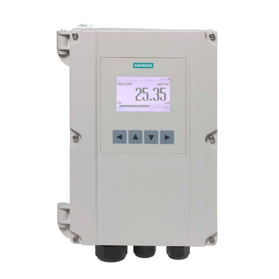
- Page 1 SITRANS F Ultrasonic Flowmeters FST020 IP65 NEMA 4X Function manual Edition 09/2017 Answers for industry.
- Page 3 Introduction Quick start Setup SITRANS F Maintenance and diagnostics Ultrasonic Flowmeters FST020 Function manual Communication Security Function Manual Language Support 09/2017 A5E42949526-AA...
- Page 4 Note the following: WARNING Siemens products may only be used for the applications described in the catalog and in the relevant technical documentation. If products and components from other manufacturers are used, these must be recommended or approved by Siemens. Proper transport, storage, installation, assembly, commissioning, operation and maintenance are required to ensure that the products operate safely and without any problems.
-
Page 5: Table Of Contents
Upstream distance ........................23 3.1.4.4 Type of downstream condition ....................23 3.1.4.5 Downstream distance ......................23 3.1.5 Medium characteristics ......................24 3.1.5.1 Process medium type ......................24 3.1.5.2 Expected sound velocity ......................24 FST020 Function manual Function Manual, 09/2017, A5E42949526-AA... - Page 6 3.2.2.1 Units ............................41 3.2.2.2 Custom units .......................... 41 3.2.2.3 Custom conversion factor ...................... 42 3.2.2.4 Decimal places ........................42 3.2.2.5 Low flow cut-off ........................42 3.2.2.6 Alarm and warning limits ......................43 FST020 Function manual Function Manual, 09/2017, A5E42949526-AA...
- Page 7 3.4.2.4 Current output ......................... 71 3.4.2.5 Off delay ..........................74 3.4.3 Channel 3 - relay ........................74 3.4.3.1 Operation mode ........................74 3.4.3.2 Status mode ..........................74 3.4.3.3 Sensor alarms (1) ........................75 FST020 Function manual Function Manual, 09/2017, A5E42949526-AA...
- Page 8 Date and time ......................... 88 3.5.1 Current date and time ......................88 3.5.2 Set date and time ........................89 Local display .......................... 89 3.6.1 FST020 - Display ........................89 3.6.2 Brightness ..........................90 3.6.3 Backlight ..........................90 3.6.4 Contrast ..........................90 Damping ..........................
- Page 9 4th process value ........................112 3.12.7 5th process value ........................112 3.12.8 6th process value ........................112 3.12.9 Trend scale mode ......................... 113 3.12.10 Trend log time window ......................113 3.12.11 Trend scale lower limit ......................113 FST020 Function manual Function Manual, 09/2017, A5E42949526-AA...
- Page 10 Serial number (read only) ....................128 4.1.20.4 Sensor type (read only) ......................128 4.1.20.5 Sensor firmware version (read only) ..................128 4.1.20.6 Frontend variant (read only) ....................128 Diagnostic events ......................... 129 4.2.1 Active diagnostic events ...................... 129 FST020 Function manual Function Manual, 09/2017, A5E42949526-AA...
- Page 11 Peak values .......................... 149 4.5.1 Process value 1 ........................149 4.5.1.1 Process value ........................149 4.5.1.2 Maximum ..........................149 4.5.1.3 Timestamp at maximum......................149 4.5.1.4 Minimum ..........................149 4.5.1.5 Timestamp at minimum......................150 FST020 Function manual Function Manual, 09/2017, A5E42949526-AA...
- Page 12 Flow velocity ......................... 163 4.8.2.5 Sound velocity ........................164 4.8.2.6 Density ..........................164 4.8.2.7 Kinematic viscosity ....................... 164 4.8.2.8 Medium temperature ......................165 4.8.3 Simulate alarms ........................165 4.8.3.1 Simulation mode ........................165 FST020 Function manual Function Manual, 09/2017, A5E42949526-AA...
- Page 13 5.2.8.9 Service channel (USB)......................180 Security .............................. 181 Change user PIN ........................181 Change expert PIN code (expert) ..................181 Recovery ID .......................... 181 PIN recovery ......................... 182 Activate user PIN ........................182 FST020 Function manual Function Manual, 09/2017, A5E42949526-AA...
- Page 14 Table of contents Deactivate user PIN ......................182 Auto logout ........................... 182 Auto logout ........................... 183 Logout ..........................183 Language ............................185 Language ..........................185 Support ..............................187 Technical support ......................... 187 Index ..............................189 FST020 Function manual Function Manual, 09/2017, A5E42949526-AA...
-
Page 15: Introduction
Note This Function Manual applies to the SITRANS FST020 only. The FST020 transmitter can be connected to sensor types FSS200 and FSS300. Purpose of this documentation This manual contains a description of all device parameters and is aimed at persons configuring the device. -
Page 16: Product Compatibility
• commission the product, (setting parame- • via PIA Life Cycle Portal ters via HMI menu) operate and maintain the device on a daily • basis troubleshoot and remedy minor operation • interruptions FST020 Function manual Function Manual, 09/2017, A5E42949526-AA... - Page 17 • operators accessed via the local display (HMI) Hardcopy can be purchased • via PIA Life Cycle Portal guide to setting parameters to obtain opti- • mum operation of the device FST020 Function manual Function Manual, 09/2017, A5E42949526-AA...
- Page 18 Introduction 1.7 Device documentation package FST020 Function manual Function Manual, 09/2017, A5E42949526-AA...
-
Page 19: Quick Start
Quick start Introduction The quick start wizard topics and introductory explanations are listed below. For detailed quick start wizard procedures refer to the FST020 Operating Instructions manual. Quick commissioning Description Quick commissioning - The Quick commissioning wizard will guide you through configuration of parameters essential for your application. - Page 20 Quick start 2.6 Copy configuration FST020 Function manual Function Manual, 09/2017, A5E42949526-AA...
-
Page 21: Setup
3.1.3.2 Pipe size Description Pipe size - Read only. Can only be changed via the Sensor Wizard. Indicates the pipe class chosen from the pipe data library included in the sensor setup wizard. FST020 Function manual Function Manual, 09/2017, A5E42949526-AA... -
Page 22: Outer Pipe Diameter
Setup → Sensor settings → Pipe settings → Pipe material 3.1.3.6 Wall sound velocity Description Pipe wall material sound velocity (clamp-on). Use the shear velocity for metallic pipes. Use the longitudinal velocity for plastic pipes. FST020 Function manual Function Manual, 09/2017, A5E42949526-AA... -
Page 23: Liner Settings
Path Setup → Sensor settings → Pipe settings → Liner settings → Liner material 3.1.3.7.3 Liner sound velocity Description Liner material sound velocity (clamp-on). Setting 200.0 m/s to 4000.0 m/s Default 2000.0 m/s FST020 Function manual Function Manual, 09/2017, A5E42949526-AA... -
Page 24: Inner Pipe Roughness
Upstream and downstream conditions 3.1.4.1 Disturbed flow profile compensation Description Disturbed flow profile compensation enable/disable Setting Enable; Disabled Default Disabled Related Path Setup → Sensor settings → Upstream and downstream conditions → Disturbed flow profile compensation FST020 Function manual Function Manual, 09/2017, A5E42949526-AA... -
Page 25: Type Of Upstream Condition
Path Setup → Sensor settings → Upstream and downstream conditions → Type of downstream condition 3.1.4.5 Downstream distance Description The distance to the downstream flow disturbance. The distance is given in pipe diameters. FST020 Function manual Function Manual, 09/2017, A5E42949526-AA... -
Page 26: Medium Characteristics
Process temperature Description Temperature of media used for compensation. Input during setup. Setting -273.0 °C to 400.0 °C Default 20.0 °C Related Path Setup → Sensor settings → Medium characteristics → Process temperature FST020 Function manual Function Manual, 09/2017, A5E42949526-AA... -
Page 27: Kinematic Viscosity
Read only: FSS200 high precision; FSS200 / 1011 Universal; FSS200 / 991 high tempera- ture; 1011 high precision liquid Default FSS200 / 1011 Universal Related Path Setup → Sensor settings → Sensor selection → Sensor model FST020 Function manual Function Manual, 09/2017, A5E42949526-AA... -
Page 28: Clamp-On Sensor Size
The velocity at which the wave fronts traverse the interface between the wedge and pipe. Access level: Expert user only. Setting 1000.0 m/s to 20000.0 m/s Default 3695.5 m/s Related Path Setup → Sensor settings → Sensor settings → Sensor phase velocity FST020 Function manual Function Manual, 09/2017, A5E42949526-AA... -
Page 29: Sensor Inactive Wedge
Related Path Setup → Sensor settings → Sensor settings → Mounting hole offset 3.1.6.9 Spacing offset Description Sensor spacing offset Setting MIN; NOM; MAX and A,B, C, D for High Temperature sensors Default FST020 Function manual Function Manual, 09/2017, A5E42949526-AA... -
Page 30: Temperature Code Of The Sensor
Length of sensor cable between transmitter/DSL and any sensors. All cables must have the same length. Setting 0.0 m to 20.0 m Default 0.0 m Related Path Setup → Sensor settings → Sensor selection → Length of sensor cables FST020 Function manual Function Manual, 09/2017, A5E42949526-AA... -
Page 31: Path Settings
The number of crossings the signal makes through the pipe (Reflect or Direct geometry for Path 1). For example: Direct (1 traverse) Reflect (2 traverse) Direct (3 traverse) Reflect (4 traverse) Setting 1 to 10 Default FST020 Function manual Function Manual, 09/2017, A5E42949526-AA... - Page 32 5 to 300 Default Related Path Setup → Sensor settings → Path settings → Path 1 → Zero point adjustment → Time duration 3.1.7.2.5 Serial number Description Serial number of sensor (clamp-on) Setting Default FST020 Function manual Function Manual, 09/2017, A5E42949526-AA...
-
Page 33: Path Diagnostic Alarm Limits
Sets the limit for the RxGain value. If the RxGain goes above this limit for any installed path, an alarm will be issued. Setting Min: 0.0 dB; Max: 100.0 dB Default 50.0 dB FST020 Function manual Function Manual, 09/2017, A5E42949526-AA... -
Page 34: User Calibration
Setup → Sensor settings → User calibration → Slope 3.1.8.2 Path 1 offset Description User calibrated zero offset for path 1. Delta time offset correction value, which can be determined at zero flow. Setting -1250ns to 1250ns Default FST020 Function manual Function Manual, 09/2017, A5E42949526-AA... -
Page 35: Multipoint Calibration
● Bidirectional: The first 10 calibration points are used for positive flow calibration and the 10 last calibration points are used for negative flow calibration. Setting Unidirectional; Bidirectional Default Unidirectional Related Path Setup → Sensor settings → Asymmetric calibration table FST020 Function manual Function Manual, 09/2017, A5E42949526-AA... -
Page 36: Calibration Point
Setup → Sensor settings → Multipoint calibration → Multipoint calibration table → Calibration points 1 - 20 3.1.9.4.2 Calibration value Description Calibration correction factor that is associated to Calibration points 1 through 20. Access level: Expert user only. Setting 0.5 to 2.0 Default FST020 Function manual Function Manual, 09/2017, A5E42949526-AA... -
Page 37: Flow Direction
This may be necessary for the smaller SONO sensors which can saturate the amplifiers even with the pre-amp off. Setting Auto; Off; On; Half transmit amplitude Default Auto FST020 Function manual Function Manual, 09/2017, A5E42949526-AA... -
Page 38: Number Of Pulses To Be Transmitted
The minimum ringdown delay setting for optimized signal processing is: 2000.000122 μs 3.1.11.4 Electronic time delay Description The time delay induced by the DSL electronics. Access level: Expert user only. Read only. The time delay induced by the DSL electronincs is: 0.519 μs FST020 Function manual Function Manual, 09/2017, A5E42949526-AA... -
Page 39: Configuration Of Test Blocks
Do not run the test block configuration procedure if configuration data is needed. Back up and record data as necessary. The wizard configures the device for use with the Siemens sensor test blocks including sensor size and sensor path. It also allows for saving the setting. -
Page 40: Process Values
Setup → Process values → Volume flow → Units 3.2.1.2 Custom units Description User specific text string for volume flow unit values. The custom units can then be selected in volume flow units. Setting Default FST020 Function manual Function Manual, 09/2017, A5E42949526-AA... -
Page 41: Custom Conversion Factor
Volume flow limit for low flow cut off. Below limit volume flow output is forced to zero. Setting 0.00 m /h to 896.40 m /h (depends on sensor) Default 0.1% of maximum flow (depends on sensor) Related Path Setup → Process values → Volume flow → Low flow cut-off FST020 Function manual Function Manual, 09/2017, A5E42949526-AA... -
Page 42: Alarm And Warning Limits
Setup → Process values → Volume flow → Alarm and warning limits → Lower warning limit 3.2.1.6.4 Lower alarm limit Description Set Lower alarm limit. Alarm is triggered if measured value is below the limit. FST020 Function manual Function Manual, 09/2017, A5E42949526-AA... -
Page 43: Mass Flow
(pounds per day); custom units (see Custom units / Custom conversion factor) Default kg/h (kilograms per hour) Related Path Setup → Process values → Mass flow → Units 3.2.2.2 Custom units Description User specific string for mass flow values. FST020 Function manual Function Manual, 09/2017, A5E42949526-AA... -
Page 44: Custom Conversion Factor
Mass flow limit for low flow cut off. Below limit mass flow output is forced to zero. Setting 0.00 to 3682800.00 kg/h (depends on sensor) Default 0.1% of maximum mass flow (depends on sensor) Related Path Setup → Process values → Mass flow → Low flow cut-off FST020 Function manual Function Manual, 09/2017, A5E42949526-AA... -
Page 45: Alarm And Warning Limits
Setup → Process values → Mass flow → Alarm and warning limits → Lower warning limit 3.2.2.6.4 Lower alarm limit Description If mass flow value falls below this limit an alarm is triggered. FST020 Function manual Function Manual, 09/2017, A5E42949526-AA... -
Page 46: Units
Setup → Process values → Flow velocity → Units 3.2.3.2 Custom units Description User specific text string to define custom unit values. The custom unit can then be selected in the flow velocity units. FST020 Function manual Function Manual, 09/2017, A5E42949526-AA... -
Page 47: Custom Conversion Factor
Flow velocity limit for low flow cut off. Below limit flow velocity output is forced to zero. Setting Min 0.00 Default 0.0 m/s Related Path Setup → Process values → Flow velocity → Low flow cut-off FST020 Function manual Function Manual, 09/2017, A5E42949526-AA... -
Page 48: Alarm And Warning Limits
Setup → Process values → Flow velocity → Alarm and warning limits → Lower warning limit 3.2.3.6.4 Lower alarm limit Description If the process value falls below this limit an alarm is triggered. FST020 Function manual Function Manual, 09/2017, A5E42949526-AA... -
Page 49: Sound Velocity
(feet per second); ft/min (feet per minute); Custom units (see Custom units / Custom conversion factor) Default m/s (meters per second) Related Path Setup → Process values → Sound velocity → Units FST020 Function manual Function Manual, 09/2017, A5E42949526-AA... -
Page 50: Custom Units
2 decimal places Related Path Setup → Process values → Sound velocity → Decimal places 3.2.4.5 Alarm and warning limits 3.2.4.5.1 Upper alarm limit Description If process value exceeds this limit an alarm is triggered. FST020 Function manual Function Manual, 09/2017, A5E42949526-AA... - Page 51 If the process value falls below this limit an alarm is triggered. Setting -9999997952 m/s to +9999997952 m/s Default -9999997952 m/s Related Path Setup → Process values → Sound velocity → Alarm and warning limits → Lower alarm limit FST020 Function manual Function Manual, 09/2017, A5E42949526-AA...
-
Page 52: Density
User specific text string to define custom unit values. The custom unit can then be selected in the density units. Setting Default Related Path Setup → Process values → Density → Custom units FST020 Function manual Function Manual, 09/2017, A5E42949526-AA... -
Page 53: Custom Conversion Factor
900.00 kg/m³ Related Path Setup → Process values → Density → Alarm and warning limits → Upper alarm limit 3.2.5.5.2 Upper warning limit Description If density value exceeds this limit a warning is triggered. FST020 Function manual Function Manual, 09/2017, A5E42949526-AA... - Page 54 Sets the hysteresis for alarm and warning limits. The hysteresis is the distance between the limits for activation and deactivation of an alarm/warning. Setting 0.00 kg/m³ to +10000.00 kg/m³ Default 0.00 kg/m³ Related Path Setup → Process values → Density → Alarm and warning limits → Hysteresis FST020 Function manual Function Manual, 09/2017, A5E42949526-AA...
-
Page 55: Kinematic Viscosity
If process value exceeds this limit an alarm is triggered. Setting -9999997952 m²/s to +9999997952 m²/s Default +9999997952 m²/s Related Path Setup → Process values → Standard kinematic viscosity → Alarm and warning limits → Up- per alarm limit FST020 Function manual Function Manual, 09/2017, A5E42949526-AA... - Page 56 Setup → Process values → Kinematic viscosity → Alarm and warning limits → Lower alarm limit 3.2.6.3.5 Hysteresis Description Sets the hysteresis for alarm and warning limits. The hysteresis is the distance between the limits for activation and deactivation of an alarm/warning. FST020 Function manual Function Manual, 09/2017, A5E42949526-AA...
-
Page 57: Medium Temperature
5 decimal places; 6 decimal places Default 2 decimal places Related Path Setup → Process values → Medium temperature → Decimal places 3.2.7.3 Alarm and warning limits 3.2.7.3.1 Upper alarm limit Description Exceeding this limit causes an alarm. FST020 Function manual Function Manual, 09/2017, A5E42949526-AA... - Page 58 -270.00 °C Related Path Setup → Process values → Medium temperature → Alarm and warning limits → Lower warn- ing limit 3.2.7.3.4 Lower alarm limit Description Falling below this limit causes an alarm. FST020 Function manual Function Manual, 09/2017, A5E42949526-AA...
-
Page 59: Totalizers
3.3.1 Totalizer 1 3.3.1.1 Process value Description Select the process value to be totalized. Setting Mass flow; Volume flow Default Volume flow Related Path Setup → Totalizers → Totalizer 1 → Process value FST020 Function manual Function Manual, 09/2017, A5E42949526-AA... -
Page 60: Units
Setup → Totalizers → Totalizer 1→ Custom units 3.3.1.4 Custom conversion factor Description Conversion factor for user specific standard mass flow values related to SI kg. Setting Default Related Path Setup → Totalizers → Totalizer 1 → Custom conversion factor FST020 Function manual Function Manual, 09/2017, A5E42949526-AA... -
Page 61: Decimal Places
RUN; totalization is continued using the bad input value Related Path Setup → Totalizers → Totalizer 1 → Fail safe mode 3.3.1.8 Reset Description Reset totalizer to zero. Setting Cancel; OK Default Cancel FST020 Function manual Function Manual, 09/2017, A5E42949526-AA... -
Page 62: Preset
Related Path Setup → Totalizers → Totalizer 1 → Alarm and warning limits → Upper alarm limit 3.3.1.10.2 Upper warning limit Description Warning is triggered if Totalizer 1 value is above the limit. FST020 Function manual Function Manual, 09/2017, A5E42949526-AA... - Page 63 Setup → Totalizers → Totalizer 1 → Alarm and warning limits → Lower alarm limit 3.3.1.10.5 Hysteresis Description Hysteresis sets the alarm and warning limits. The hysteresis is the distance between the limits for activation and deactivation of an alarm/warning. FST020 Function manual Function Manual, 09/2017, A5E42949526-AA...
-
Page 64: Inputs And Outputs
All four channels can be configured as current output. Current output configuration The following process values can be assigned to the current output: ● Volume flow ● Mass flow ● Sound velocity ● Flow velocity ● Density FST020 Function manual Function Manual, 09/2017, A5E42949526-AA... - Page 65 ● Fail-safe value (within the range of 0 mA to 25 mA For channel 1 the range is 3.5 mA to 25 mA Output scaling configuration Below are four examples describing configuration possibilities for a current output. FST020 Function manual Function Manual, 09/2017, A5E42949526-AA...
- Page 66 ● Loop current scale = 4-20 mA (maximum 25 mA) ● Upper range value = 100 kg/h ● Lower range value = 400 kg/h ● Fail-safe behaviour = Upper fault current ● Low flow cut-off = 25 kg/h FST020 Function manual Function Manual, 09/2017, A5E42949526-AA...
- Page 67 ● Loop current scale = 4-20 mA NAMUR ● Upper range value = 400 kg/h ● Lower range value = -100 kg/h ● Fail-safe behaviour = Upper fault current ● Low flow cut-off = 25 kg/h FST020 Function manual Function Manual, 09/2017, A5E42949526-AA...
- Page 68 ● Loop current scale = 4-20 mA US ● Upper range value = 400 kg/h ● Lower range value = -100 kg/h ● Fail-safe behaviour = Minimum current ● Low flow cut-off = 25 kg/h FST020 Function manual Function Manual, 09/2017, A5E42949526-AA...
- Page 69 The pulse output function supplies pulses equivalent to a configured amount of accumulated volume or mass. The pulse width is configured and the pulse repetition is proportional to the selected flow rate. Pulse repetition Pulse repetition is calculated as follows: FST020 Function manual Function Manual, 09/2017, A5E42949526-AA...
- Page 70 ● Process value = Mass flow ● Direction = Positive ● Frequency value high = 12 kHz ● Frequency value low = 2 kHz ● Upper range value = 15 kg/s ● Lower range value = 5 kg/s FST020 Function manual Function Manual, 09/2017, A5E42949526-AA...
-
Page 71: Alarm Status
● Alarm item: Alarm will be signaled if selected alarm item occurs. It is possible to select multiple alarms to be signaled. Note Alarm class / NAMUR status signals The options depend on the setting selected in Status icons, either NAMUR status signals or Alarm class (Siemens Standard). FST020 Function manual Function Manual, 09/2017, A5E42949526-AA... -
Page 72: Channel 2 - Output
Active operation not possible, use passive wiring; Active operation possible, hardware is able to drive the current loop Default Related Path Setup → Inputs and outputs → Channel 2 - output → Active operation FST020 Function manual Function Manual, 09/2017, A5E42949526-AA... -
Page 73: Fail-Safe Activation Condition
(only hydrocarbon and gas applications). Setting Positive; Negative; Bidirectional; Bidirectional (symmetric) Default Positive Related Path Setup → Inputs and outputs → Channel 2 - output → Current output → Direction FST020 Function manual Function Manual, 09/2017, A5E42949526-AA... - Page 74 Sets value at 0% of measuring span and corresponds to a loop current of 0/4 mA. Setting and Default are sensor specific, depending on the setting in Process value and depending on the Units setting. Setting -3682800.00 kg/h to +3682800.00 kg/h Default 0.00 kg/h FST020 Function manual Function Manual, 09/2017, A5E42949526-AA...
- Page 75 Output value in case of a fault and when fail-safe behaviour configured to fail-safe value. Setting 0.0 mA to 25.0 mA Default 0.0 mA Related Path Setup → Inputs and outputs → Channel 2 - output → Current output → Fail-safe value FST020 Function manual Function Manual, 09/2017, A5E42949526-AA...
-
Page 76: Off Delay
Alarm class; Alarm item Default Alarm class Related Path Setup → Inputs and outputs → Channel 3 - relay → Operation mode 3.4.3.2 Status mode Description Select the functionality for the status output. FST020 Function manual Function Manual, 09/2017, A5E42949526-AA... -
Page 77: Sensor Alarms (1)
Setup → Inputs and outputs → Channel 3 - relay → Sensor alarms (2) 3.4.3.5 Process alarms (1) Description Selection of alarm items that impact the output. Applicable if Status mode = Alarm item. FST020 Function manual Function Manual, 09/2017, A5E42949526-AA... -
Page 78: Process Alarms (3)
Selection of alarm items that impact the output. Applicable if Status mode = Alarm item. For hydrocarbon and gas applications only. Setting 285 Datalogging; 286 Datalogging; 287 Datalogging Default None Related Path Setup → Inputs and outputs → Channel 3 - relay → Process alarms (4) FST020 Function manual Function Manual, 09/2017, A5E42949526-AA... -
Page 79: Totalizer Alarms
Setup → Inputs and outputs → Channel 3 - relay → Device alarms 3.4.3.10 Input/output alarms (1) Description Selection of alarm items that impact the output. Applicable if Status mode = Alarm item. Availability of certain settings depends on Hardware and Software configuration. FST020 Function manual Function Manual, 09/2017, A5E42949526-AA... -
Page 80: Simulation Alarms (1)
289 Sound velocity simulated; 290 Flow velocity simulated; 292 Kin. viscosity simulated; 300 Std. Kin. viscosity simulated Default None Related Path Setup → Inputs and outputs → Channel 3 - relay → Simulation alarms (2) FST020 Function manual Function Manual, 09/2017, A5E42949526-AA... -
Page 81: Alarm Class
3.4.3.15 Polarity Description Logical polarity of status output. Setting Active high level; Active low level Default Active high level Related Path Setup → Inputs and outputs → Channel 3 - relay → Polarity FST020 Function manual Function Manual, 09/2017, A5E42949526-AA... -
Page 82: On Delay
Shows the configured Operation mode. Use Change operation mode to set the mode. Read only. Setting Off; Frequency output; Pulse output Default Related Path Setup → Inputs and outputs → Channel 4 - input/output → Operation mode FST020 Function manual Function Manual, 09/2017, A5E42949526-AA... -
Page 83: Change Operation Mode
(only hydrocarbon and gas applications). Setting Positive; Negative; Bidirectional; Bidirectional (symmetric) Default Positive Related Path Setup → Inputs and outputs → Channel 4 - input/output → Frequency output → Direction FST020 Function manual Function Manual, 09/2017, A5E42949526-AA... - Page 84 Setup → Inputs and outputs → Channel 4 - input/output → Frequency output → Upper range value 3.4.3.3.6 Lower range value Description Sets value at 0% of measuring span and corresponds to Frequency value low. FST020 Function manual Function Manual, 09/2017, A5E42949526-AA...
- Page 85 Setup → Inputs and outputs → Channel 4 - input/output → Frequency output → Fail-safe behaviour 3.4.3.3.9 Fail-safe minimum time Description Minimum time the output stays in fail-safe mode. Setting 0 s to 100 s Default FST020 Function manual Function Manual, 09/2017, A5E42949526-AA...
-
Page 86: Pulse Output
Setup → Inputs and outputs → Channel 4 - input/output → Pulse output → Process value 3.4.3.4.2 Direction Description Flow direction filter. Setting Positive; Negative; Bidirectional; Bidirectional (symmetric) Default Positive Related Path Setup → Inputs and outputs → Channel 4 - input/output → Pulse output → Direction FST020 Function manual Function Manual, 09/2017, A5E42949526-AA... - Page 87 Related Path Setup → Inputs and outputs → Channel 4 - input/output → Pulse outputs → Custom conver- sion factor 3.4.3.4.6 Amount per pulse Description Amount of value to generate an output pulse. FST020 Function manual Function Manual, 09/2017, A5E42949526-AA...
- Page 88 Logical polarity of pulse output. Setting Active high level; Active low level Default Active high level Related Path Setup → Inputs and outputs → Channel 4 - input/output → Pulse output → Polarity FST020 Function manual Function Manual, 09/2017, A5E42949526-AA...
- Page 89 Minimum time the output stays in fail safe mode. Setting 0 s to 100 s Default Related Path Setup → Inputs and outputs → Channel 4 - input/output → Pulse output → Fail-safe minimum time FST020 Function manual Function Manual, 09/2017, A5E42949526-AA...
-
Page 90: Channel 7 - Digital Input
Related Path Setup → Inputs and outputs → Channel 8 - digital input → Input function Date and time 3.5.1 Current date and time Description Displays the current date and time. Read only. FST020 Function manual Function Manual, 09/2017, A5E42949526-AA... -
Page 91: Set Date And Time
Setup → Date and time → Set date and time Local display 3.6.1 FST020 - Display The system can be configured to show up to six different views. In view 1 only measurement or diagnostic views can be selected. In views 2 to 6 all view types can be selected. -
Page 92: Brightness
Setup → Local display → Backlight 3.6.4 Contrast Description Adjust contrast to improve local display conditions. Setting 0%; 10%; 20%; 30%; 40%; 50%; 60%; 70%; 80%; 90%; 100% Default Related Path Setup → Local display → Contrast FST020 Function manual Function Manual, 09/2017, A5E42949526-AA... -
Page 93: Damping
Available process values for the meter. Setting API gravity; Standard API gravity; Specific gravity; Standard specific gravity; Rate of change Default Specific gravity Related Path Setup → Local display → Damping → Process values (2) FST020 Function manual Function Manual, 09/2017, A5E42949526-AA... -
Page 94: View 1
Volume flow; Mass flow; Flow velocity; Sound velocity; Density; Kinematic viscosity; Medi- um temperature Default Volume flow Related Path Setup → Local display → View 1 → 1st value 3.8.3 Graph scale mode Description Graph scale mode FST020 Function manual Function Manual, 09/2017, A5E42949526-AA... -
Page 95: 2Nd Value
Medium temperature Related This parameter is only available if View 1 is set to Three values, Six values or Six diagnostic values. Path Setup → Local display → View 1 → 3rd value FST020 Function manual Function Manual, 09/2017, A5E42949526-AA... -
Page 96: 4Th Process Value
Default Fluid temperature Related This parameter is only available if View 1 is set to Six values or Six diagnostic values. Path Setup → Local display → View 1 → 6th process value FST020 Function manual Function Manual, 09/2017, A5E42949526-AA... -
Page 97: Trend Scale Mode
The Trend scale lower limit defines the scaling lower limit of the value axis for the fixed mode. Setting Default Related This parameter is only available if Trend scale mode is set to Fixed. Path Setup → Local display → View 1 → Trend scale lower limit FST020 Function manual Function Manual, 09/2017, A5E42949526-AA... -
Page 98: Trend Scale Upper Limit
View Description The display View 2 can be configured. Setting Single value; Three values; Totalizer; 1 value and bargraph; 1 value and graph; Six values; Six diagnostic values; Alarm list Default Single value FST020 Function manual Function Manual, 09/2017, A5E42949526-AA... -
Page 99: 1St Value
Mass flow; Volume flow; Density; Fluid Temperature; Totalizer 1 Default Density Related This parameter is only available if View is set to Three Values, Six Values or Six Diagnostic Values. Path Setup → Display → View 2 → 2nd Process Value FST020 Function manual Function Manual, 09/2017, A5E42949526-AA... -
Page 100: 3Rd Process Value
Density; Totalizer 1; Totalizer 2; Totalizer 3 Default Totalizer 1 Related This parameter is only available if View is set to Six Values or Six Diagnostic Values. Path Setup → Display → View 2 → 5th Process Value FST020 Function manual Function Manual, 09/2017, A5E42949526-AA... -
Page 101: 6Th Process Value
1 Minute; 5 Minutes; 15 Minutes; 30 Minutes; 1 Hour; 2 Hours; 3 Hours Default 5 Minutes Related This parameter is only available if View is set to Totalizer or 1 Value and Graph. Path Setup → Display → View 2 → Trend log time window FST020 Function manual Function Manual, 09/2017, A5E42949526-AA... -
Page 102: Trend Scale Lower Limit
Path Setup → Display → View 2 → Trend Scale Upper Limit 3.10 View 3 3.10.1 Enable or disable Description In this parameter View 3 can be enabled. Setting Disabled; Enabled Default Enabled FST020 Function manual Function Manual, 09/2017, A5E42949526-AA... -
Page 103: View
The display 1st Process Value can be selected. This process value is shown in all view types. Setting Volume flow; Mass flow; Flow velocity; Sound velocity; Density; Kinematic viscosity; Total- izer 1; Medium Temperature Default Volume flow Related Path Setup → Display → View 3 → 1st Value FST020 Function manual Function Manual, 09/2017, A5E42949526-AA... -
Page 104: Graphic Scale Mode
Default Sound velocity Related This parameter is only available if View is set to Three Values, Six Values or Six Diagnostic Values. Path Setup → Display → View 3 → 3rd Process Value FST020 Function manual Function Manual, 09/2017, A5E42949526-AA... -
Page 105: 4Th Process Value
Mass flow; Volume flow; Density; Fluid Temperature; Totalizer 1 Default Totalizer 1 Related This parameter is only available if View is set to Six Values or Six Diagnostic Values. Path Setup → Display → View 3 → 6th Process Value FST020 Function manual Function Manual, 09/2017, A5E42949526-AA... -
Page 106: Trend Scale Mode
The Trend Scale Lower Limit defines the scaling lower limit of the value axis for the fixed mode. Setting Default Related This parameter is only available if Trend Scale Mode is set to Fixed. Path Setup → Display → View 3 → Trend Scale Lower Limit FST020 Function manual Function Manual, 09/2017, A5E42949526-AA... -
Page 107: Trend Scale Upper Limit
Description The display View 4 can be configured. Setting Single value; Three values; Totalizer; 1 value and bargraph; 1 value and graph; Six values; Six diagnostic values; Alarm list Default Six diagnostic values FST020 Function manual Function Manual, 09/2017, A5E42949526-AA... -
Page 108: 1St Value
Peak amplitude up path 1; Peak amplitude down path 1; Min acc travel time path 1; Min acc travel time path 1; Max acc travel time path 1 Default Flow velocity path 1 FST020 Function manual Function Manual, 09/2017, A5E42949526-AA... -
Page 109: 3Rd Value
Min acc travel time path 1; Min acc travel time path 1; Max acc travel time path 1 Default Flow velocity path 1 Related This parameter is only available if View is set to Six Values or Six Diagnostic Values. Path Setup → Display → View 4 → 4th Value FST020 Function manual Function Manual, 09/2017, A5E42949526-AA... -
Page 110: 5Th Value
Path Setup → Display → View 4 → 6th value 3.11.9 Trend scale mode Description The Trend Scale Mode can be selected with automatic scaling or fixed scaling. Setting Auto; Fixed Default Auto FST020 Function manual Function Manual, 09/2017, A5E42949526-AA... -
Page 111: Trend Log Time Window
Setup → Display → View 4 → Trend Scale Lower Limit 3.11.12 Trend scale upper limit Description The Trend Scale Upper Limit defines the scaling upper limit of the value axis for the fixed mode. FST020 Function manual Function Manual, 09/2017, A5E42949526-AA... -
Page 112: View 5
Trend log time window must be configured. If 1 Value and Bargraph is selected, 1st Process Value must be configured. If Six Values or Six Diagnostic Values is selected, 1st Process Value , 2nd Process Value, FST020 Function manual Function Manual, 09/2017, A5E42949526-AA... -
Page 113: 1St Value
Setup → Display → View 5 → 2nd value 3.12.5 3rd value Description The display 3rd Process Value can be selected. Setting Volume flow; Mass flow; Flow velocity; Sound velocity; Density; Kinematic viscosity; Total- izer 1; Medium temperature Default Medium temperature FST020 Function manual Function Manual, 09/2017, A5E42949526-AA... -
Page 114: 4Th Process Value
Setup → Display → View 5 → 5th value 3.12.8 6th process value Description The display 6th Process Value can be selected. Setting Mass flow; Volume flow; Density; Fluid Temperature; Totalizer 1 Default Totalizer 1 FST020 Function manual Function Manual, 09/2017, A5E42949526-AA... -
Page 115: Trend Scale Mode
Setup → Display → View 5 → Trend log time window 3.12.11 Trend scale lower limit Description The Trend Scale Lower Limit defines the scaling lower limit of the value axis for the fixed mode. FST020 Function manual Function Manual, 09/2017, A5E42949526-AA... -
Page 116: Trend Scale Upper Limit
In this parameter View 6 can be enabled. Setting Disabled; Enabled Default Enabled Related If Enabled is selected, all parameters for View 6 must be configured. Path Setup → Display → View 6 → Enable or disable FST020 Function manual Function Manual, 09/2017, A5E42949526-AA... -
Page 117: View
Setup → Display → View 6 → 1st Process Value 3.13.4 2nd process value Description The display 2nd Process Value can be selected. Setting Mass flow; Volume flow; Density; Fluid Temperature; Totalizer 1 Default Density FST020 Function manual Function Manual, 09/2017, A5E42949526-AA... -
Page 118: 3Rd Process Value
Setup → Display → View 6 → 4th Process Value 3.13.7 5th process value Description The display 5th Process Value can be selected. Setting Mass flow; Volume flow; Density; Fluid Temperature; Totalizer 1 Default Totalizer 1 FST020 Function manual Function Manual, 09/2017, A5E42949526-AA... -
Page 119: 6Th Process Value
Trend log time window Description The Trend log time window logging period (time axis length) can be selected. Setting 1 Minute; 5 Minutes; 15 Minutes; 30 Minutes; 1 Hour; 2 Hours; 3 Hours Default 5 Minutes FST020 Function manual Function Manual, 09/2017, A5E42949526-AA... -
Page 120: Trend Scale Lower Limit
This parameter is only available if Trend Scale Mode is set to Fixed. Path Setup → Display → View 6 → Trend Scale Upper Limit 3.14 Status icons Description Sets the type of status icons used for diagnostic events. Setting Standard; NAMUR Default Standard FST020 Function manual Function Manual, 09/2017, A5E42949526-AA... - Page 121 Setup 3.14 Status icons Related Path Setup → Local display→ Status icons FST020 Function manual Function Manual, 09/2017, A5E42949526-AA...
- Page 122 Setup 3.14 Status icons FST020 Function manual Function Manual, 09/2017, A5E42949526-AA...
-
Page 123: Maintenance And Diagnostics
Sets unique description for device. Limited to 32 characters. Setting User-configurable Default ----------------; 16 characters (A, B, C, ... X, Y, Z, /, 1, 2, 3, ... 7, 8, 9) Related Path Maintenance and diagnostics → Identification → Descriptor FST020 Function manual Function Manual, 09/2017, A5E42949526-AA... -
Page 124: Message
----------------; 16 characters (A, B, C, ... X, Y, Z, /, 1, 2, 3, ... 7, 8, 9) Related Path Maintenance and diagnostics → Identification → Installation date 4.1.7 Manufacturer Displays manufacturer of device. Setting Default SIEMENS Related Path Maintenance and diagnostics → Identification → Manufacturer FST020 Function manual Function Manual, 09/2017, A5E42949526-AA... -
Page 125: Product Name
Also shown on the device nameplate. Setting Default Related Path Maintenance and diagnostics → Identification → System order number 4.1.11 Serial number Description Displays transmitter serial number. Also shown on the device nameplate. FST020 Function manual Function Manual, 09/2017, A5E42949526-AA... -
Page 126: Fw Version
4.1.14 Final assembly number Displays number corresponding to materials and components used in final assembly of device. Setting 0 to 4294967295 Default Related Path Maintenance and diagnostics → Identification → Final assembly number FST020 Function manual Function Manual, 09/2017, A5E42949526-AA... -
Page 127: System Type
Displays version number corresponding to software or firmware embedded in device. Setting Default Related Path Maintenance and diagnostics → Identification → FW version 4.1.16.3 Serial number Description Displays transmitter serial number. Also shown on the device nameplate. Setting Default FST020 Function manual Function Manual, 09/2017, A5E42949526-AA... -
Page 128: Order Number
Local display Description Local display Setting HW version 1.01.00 Default Setting FW version - 1.04.13-09 Default Setting HMI cfg. version - 1.00.01.39 Default Related Path Maintenance and diagnostics → Identification → Local display FST020 Function manual Function Manual, 09/2017, A5E42949526-AA... -
Page 129: I/O Electronics
Maintenance and diagnostics → Identification → Sensor → Type 4.1.20.2 Sensor type (read only) Description Identification of the sensor type. Used by the transmitter to enable technology-specific functionalities. Path Maintenance and diagnostics → Identification → Sensor → Sensor type FST020 Function manual Function Manual, 09/2017, A5E42949526-AA... -
Page 130: Serial Number (Read Only)
Sensor firmware version (read only) Description Sensor firmware version. Setting Default Related Path Maintenance and diagnostics → Identification → Sensor → Sensor firmware version 4.1.20.6 Frontend variant (read only) Description Frontend variant. Setting Remote/integrated; Compact Default FST020 Function manual Function Manual, 09/2017, A5E42949526-AA... -
Page 131: Diagnostic Events
Maintenance and diagnostics → Diagnostic events → Clear diagnostic log 4.2.4 Acknowledge mode Description The system can be configured to acknowledge the alarms automatically when they are gone (Auto), or it can be configured to require an acknowledgement from the operator (Manual). FST020 Function manual Function Manual, 09/2017, A5E42949526-AA... -
Page 132: Transmitter Detailed Events (Read Only)
Maintenance and diagnostics → Diagnostic events → Transmitter detailed events 4.2.6 Suppression time Description A coming event can be suppressed in order to prevent alarm flooding. Setting 0 to 300 s Default Path Maintenance and diagnostics → Diagnostic events → Suppression time FST020 Function manual Function Manual, 09/2017, A5E42949526-AA... -
Page 133: Enable Alarms
Maintenance and diagnostics → Diagnostic events → Enable alarms → Sensor events (2) 4.2.7.3 Process events (1) Description Various sensor alarms can be enabled to show in the display and on the output if they occur. FST020 Function manual Function Manual, 09/2017, A5E42949526-AA... -
Page 134: Process Events (2)
233 Flow velocity above warning limit; 234 Flow velocity below warning limit; 235 Flow velocity below alarm limit; 244 Kin. viscosity above alarm limit; 245 Kin. viscosity above warning limit; 246 Kin. viscosity below warning limit; 247 Kin. viscosity Default FST020 Function manual Function Manual, 09/2017, A5E42949526-AA... -
Page 135: Process Events (4)
Maintenance and diagnostics → Diagnostic events → Enable alarms → Totalizer events 4.2.7.8 Device events Description If one of the selected events appears this affects the status icon, the related status output and the alarm on the communication interface. FST020 Function manual Function Manual, 09/2017, A5E42949526-AA... -
Page 136: Simulation Events (1)
Output (2), Input/output (3) and/or Input/output (4) is set to Status output and Status mode is set to Alarm item. Path Maintenance and diagnostics → Diagnostic events → Enable alarms → Simulation events FST020 Function manual Function Manual, 09/2017, A5E42949526-AA... -
Page 137: Input/Output Events (1)
Process value alarm (PA) resp. Out of specification; Maintenance alarm resp. Failure Default Process value alarm (PA) resp. Out of specification Path Maintenance and diagnostics → Diagnostic events → Assign alarm class → 148 - Transm. temp. above alarm limit FST020 Function manual Function Manual, 09/2017, A5E42949526-AA... -
Page 138: 149 - Transm. Temp. Below Alarm Limit
Maintenance and diagnostics → Maintenance → Copy configuration 4.3.2 Spare part replacement 4.3.2.1 Transmitter 4.3.2.1.1 Replace transmitter Description Only Siemens authorized personnel may replace spare parts. Access level: Expert user only. Setting Cancel; OK Default Cancel FST020 Function manual Function Manual, 09/2017, A5E42949526-AA... -
Page 139: Operating Time
Operating time total - Indicates the total operating time of the transmitter since the last power 4.3.3 Electronic part identification 4.3.3.1 Transmitter cassette 4.3.3.1.1 HW version (expert) Description Only Siemens authorized personnel may replace spare parts. Setting Cancel; OK Default Cancel Path Maintenance and diagnostics → Maintenance → Electronic part identification → Transmitter cassette →... - Page 140 4.3 Maintenance Path Maintenance and diagnostics → Maintenance → Electronic part identification → Transmitter cassette → FW version 4.3.3.1.3 Serial number (expert) Description Only Siemens authorized personnel may replace spare parts. Setting Cancel; OK Default Cancel Path Maintenance and diagnostics → Maintenance → Electronic part identification → Transmitter cassette →...
-
Page 141: Local Display
Maintenance and diagnostics 4.3 Maintenance 4.3.3.2 Local display 4.3.3.2.1 HW version (expert) Description Only Siemens authorized personnel may replace spare parts. Setting Cancel; OK Default Cancel Path Maintenance and diagnostics → Maintenance → Electronic part identification → Local dis- play → HW version 4.3.3.2.2 FW version (expert) -
Page 142: I/O Cassette
Maintenance and diagnostics 4.3 Maintenance 4.3.3.3 I/O cassette 4.3.3.3.1 FW version (expert) Description Only Siemens authorized personnel may replace spare parts. Setting Cancel; OK Default Cancel Path Maintenance and diagnostics → Maintenance → Electronic part identification → I/O cassette → FW version 4.3.3.3.2 Serial number (expert) -
Page 143: Diagnostics
Maintenance and diagnostics 4.4 Diagnostics 4.3.3.4.2 Serial number (expert) Description Only Siemens authorized personnel may replace spare parts. Setting Cancel; OK Default Cancel Path Maintenance and diagnostics → Maintenance → Electronic part identification → Sensor cassette → Serial number Diagnostics 4.4.1... - Page 144 Maintenance and diagnostics → Diagnostics → Sensor → Path 1 → Flow velocity 4.4.1.3.7 Delta time (read only) Description Delta time. Path Maintenance and diagnostics → Diagnostics → Sensor → Path 1 → Delta time FST020 Function manual Function Manual, 09/2017, A5E42949526-AA...
-
Page 145: Temperature Monitoring
4.4.1.3.12 Peak amplitude up (read only) Description Operating time of frontend since last power-up. Path Maintenance and diagnostics → Diagnostics → Sensor → Path 1 → Peak amplitude up 4.4.2 Temperature monitoring 4.4.2.1 Medium temperature Description Medium temperature FST020 Function manual Function Manual, 09/2017, A5E42949526-AA... -
Page 146: Transmitter Electronics Temperature
→ Timestamp at minimum value 4.4.2.2.4 Maximum (read only) Description Drag indicator of maximum transmitter internal temperature. Path Maintenance and diagnostics → Diagnostics → Temperature monitoring → Transmitter elec- tronics temperature → Maximum FST020 Function manual Function Manual, 09/2017, A5E42949526-AA... -
Page 147: Inputs And Outputs
Operation mode is set to Current output, this parameter will show the current output value. Path Maintenance and diagnostics → Diagnostics → Inputs and outputs → Channel 2 - output → Channel value Description The error status of the channel can be viewed in this parameter. FST020 Function manual Function Manual, 09/2017, A5E42949526-AA... -
Page 148: Channel 3 - Relay
Maintenance and diagnostics → Diagnostics → Inputs and outputs → Channel 3 - relay → Channel value 4.4.3.3 Channel 4 - Input/output 4.4.3.3.1 Operation mode - (read only) Description The set Operation mode can be viewed in this parameter. Setting Off; Frequency output; Pulse output Default FST020 Function manual Function Manual, 09/2017, A5E42949526-AA... - Page 149 This parameter is only available if Operation mode is set to Current output, Frequency output, Pulse output or Current input. Path Maintenance and diagnostics → Diagnostics → Inputs and outputs → Channel 4 - in- put/output→ Error status FST020 Function manual Function Manual, 09/2017, A5E42949526-AA...
-
Page 150: Calibration Picture
Maintenance and diagnostics → Diagnostics → Inputs and outputs → Channel 4 - in- put/output → Reset pulse counter 4.4.3.4 Calibration picture Description Calibration picture Setting Default Related Path Maintenance and diagnostics → Diagnostics → Inputs and outputs → Calibration picture FST020 Function manual Function Manual, 09/2017, A5E42949526-AA... -
Page 151: Peak Values
This parameter is only available if Process value is not set to Disabled. Path Maintenance and diagnostics → Peak values → Process value 1 → Maximum value timestamp 4.5.1.4 Minimum Displays minimum measured value. FST020 Function manual Function Manual, 09/2017, A5E42949526-AA... -
Page 152: Timestamp At Minimum
Process value 2 4.5.2.1 Process value Description Assign the process value to be monitored. Setting Disabled; Volume flow; Mass flow; Sound velocity; Flow velocity; Density; Medium temper- ature; Kinematic viscosity; Totalizer 1 Default Disabled FST020 Function manual Function Manual, 09/2017, A5E42949526-AA... -
Page 153: Maximum
Displays timestamp when minimum value measured. Related This parameter is only available if Process value is not set to Disabled. Path Maintenance and diagnostics → Peak values → Process value 2 → Minimum value timestamp FST020 Function manual Function Manual, 09/2017, A5E42949526-AA... -
Page 154: Reset Peak Values
Maximum Displays maximum measured value. Related This parameter is only available if Process value is not set to Disabled. Path Maintenance and diagnostics → Peak values → Process value 3 → Maximum value FST020 Function manual Function Manual, 09/2017, A5E42949526-AA... -
Page 155: Timestamp At Maximum
Setting Cancel; Ok Default Cancel Related This parameter is only available if Process value is not set to Disabled. Path Maintenance and diagnostics → Peak values → Process value 3 → Reset logging FST020 Function manual Function Manual, 09/2017, A5E42949526-AA... -
Page 156: Process Value 4
Minimum Displays minimum measured value. Related This parameter is only available if Process value is not set to Disabled. Path Maintenance and diagnostics → Peak values → Process value 4 → Minimum value FST020 Function manual Function Manual, 09/2017, A5E42949526-AA... -
Page 157: Timestamp At Minimum
Maintenance and diagnostics → Peak values → Process value 4 → Reset logging Characteristics 4.6.1 Transmitter 4.6.1.1 Design (read only) Description Information about the main design features of the transmitter. Path Maintenance and diagnostics → Characteristics → Transmitter → Design FST020 Function manual Function Manual, 09/2017, A5E42949526-AA... -
Page 158: Sensorflash
Maintenance and diagnostics → SensorFlash → Installed 4.7.3 Capacity total (read only) Description Total capacity of installed SensorFlash. Shows INSERT CARD if card is not installed. Setting Default Related Path Maintenance and diagnostics → SensorFlash → Capacity total FST020 Function manual Function Manual, 09/2017, A5E42949526-AA... -
Page 159: Capacity Available (Read Only)
Select between a momentary value or an averaged value calculated over one logging interval. Setting Log instantaneous, Log average value Default Log instantaneous Related Path Maintenance and diagnostics → SensorFlash → Data logging → Data logging mode FST020 Function manual Function Manual, 09/2017, A5E42949526-AA... -
Page 160: Logging Interval
Kinematic viscosity; Totalizer 1 Default Disabled Related This parameter is only available if Data logging is enabled. Path Maintenance and diagnostics → SensorFlash → Data logging → Process values → Logging value 1...20 FST020 Function manual Function Manual, 09/2017, A5E42949526-AA... -
Page 161: Simulation
Maintenance and diagnostics → Simulation → Simulation inputs and outputs → Channel 2 - output → Simulation 4.8.1.1.3 Simulation value Description Set the current value to be output on the channel when current output simulation is enabled. FST020 Function manual Function Manual, 09/2017, A5E42949526-AA... -
Page 162: Channel 3 - Relay
Only if parameter Simulation is set to Enabled, then the setting of this parameter will be relevant. Path Maintenance and diagnostics → Simulation → Simulation inputs and outputs → Channel 3 - relay → Simulation value FST020 Function manual Function Manual, 09/2017, A5E42949526-AA... -
Page 163: Channel 4 - Input/Output
Set the pulse value to be output on the channel when pulse output simulation is enabled. Setting 0.0 Hz to 12500.0 Hz Default 1.0 Hz Operation mode is set to Frequency output FST020 Function manual Function Manual, 09/2017, A5E42949526-AA... -
Page 164: Simulation Process Values
Maintenance and diagnostics → Simulation → Simulation process values → Enable simula- tion 4.8.2.2 Volume flow Simulation value Description Set the Volume flow value to be simulated. Setting -10800000000.0 m /h to +10800000000.0 m Default 0.0 m FST020 Function manual Function Manual, 09/2017, A5E42949526-AA... -
Page 165: Mass Flow
Only if Flow velocity is marked in Enable simulation, then the setting of this parameter will be relevant. The range and default setting are dependent on the selected Unit. Path Maintenance and diagnostics → Simulation → Simulation process values → Flow velocity → Simulation value FST020 Function manual Function Manual, 09/2017, A5E42949526-AA... -
Page 166: Sound Velocity
The range and default setting are dependent on the selected Unit. Path Maintenance and diagnostics → Simulation → Simulation process values → Density → Simu- lation value 4.8.2.7 Kinematic viscosity Simulation value Description Set the Kinematic viscosity value to be simulated. FST020 Function manual Function Manual, 09/2017, A5E42949526-AA... -
Page 167: Medium Temperature
Maintenance and diagnostics → Simulation → Simulation process values → Medium tem- perature → Simulation value 4.8.3 Simulate alarms 4.8.3.1 Simulation mode Description The alarm simulation mode can be configured in this parameter. Setting Off; Simulate alarm (ID number); Simulate alarm class Default FST020 Function manual Function Manual, 09/2017, A5E42949526-AA... -
Page 168: Alarms
This parameter is only available if Simulation mode is set to Simulate alarm (ID number). Path Maintenance and diagnostics → Simulation → Simulation alarms → Alarms → Sensor alarms 4.8.3.2.3 Process alarms (1) Description The simulation of single and multiple Process alarms (1) can be configured. FST020 Function manual Function Manual, 09/2017, A5E42949526-AA... - Page 169 This parameter is only available if Simulation mode is set to Simulate alarm (ID number). Path Maintenance and diagnostics → Simulation → Simulation alarms → Alarms → Process alarms (3) 4.8.3.2.6 Process alarms (4) Description The simulation of single and multiple Process alarms (4) can be configured. FST020 Function manual Function Manual, 09/2017, A5E42949526-AA...
-
Page 170: Alarm Class
Maintenance and diagnostics → Simulation → Simulation alarms → Alarms → Input/output alarms 4.8.3.3 Alarm class Description The Siemens standard alarm class to be simulated can be configured. The alarm status is activated on all outputs. FST020 Function manual Function Manual, 09/2017, A5E42949526-AA... -
Page 171: Alarm Class
Maintenance and diagnostics → Audit trail → Parameter change log 4.9.2 Clear parameter change log (write only) Description The parameter change log can be reset using this parameter. Setting Cancel; Ok Default Cancel FST020 Function manual Function Manual, 09/2017, A5E42949526-AA... -
Page 172: Firmware Update Change Log
Maintenance and diagnostics → Audit trail → Clear FW update change log 4.10 Self test 4.10.1 Display test Description The display can be tested using a wizard.. Path Maintenance and diagnostics → Self test → Display test FST020 Function manual Function Manual, 09/2017, A5E42949526-AA... -
Page 173: Resets
Cancel Related Path Maintenance and diagnostics → Resets → Device restart 4.12 Firmware update Description The firmware of the device can be updated using a wizard. Path Maintenance and diagnostics → Firmware update FST020 Function manual Function Manual, 09/2017, A5E42949526-AA... - Page 174 Maintenance and diagnostics 4.12 Firmware update FST020 Function manual Function Manual, 09/2017, A5E42949526-AA...
-
Page 175: Communication
Communications → Service channel (USB) → Auto mode 5.1.3 MSD connect (write only) Description This command is used to connect/disconnect to a mass storage device (for example: a PC). Setting Do nothing; Connect; Disconnect Default Do nothing FST020 Function manual Function Manual, 09/2017, A5E42949526-AA... -
Page 176: Modbus (Channel 1)
Communication → Modbus (Channel 1) → Slave address (HW) 5.2.3 Baud rate Description Baud rate of Modbus interface. Setting 9600 Bit/s; 19200 Bit/s; 115200 Bit/s; 38400 Bit/s; 57600 Bit/s; 76800 Bit/s; 1200 Bit/s; 2400 Bit/s; 4800 Bit/s Default FST020 Function manual Function Manual, 09/2017, A5E42949526-AA... -
Page 177: Parity / Framing
The integer byte order used in Modbus messages. MSB = most significant byte / high byte LSB = least significant byte / low byte Setting MSB to LSB (big endian); LSB to MSB (little endian) Default FST020 Function manual Function Manual, 09/2017, A5E42949526-AA... -
Page 178: Register Mapping
Default Related Path Communication → Modbus (Channel 1) → Register mapping → Source register 1..20 5.2.7.3 Target register 1..20 Description Register of an existing product parameter to which a Modbus request is redirected. FST020 Function manual Function Manual, 09/2017, A5E42949526-AA... -
Page 179: Modbus Units
Gallons → Ugal/s; Ugal/min; Ugal/h; Ugal/d; Mgal/d; gal/s; gal/min; gal/h; gal/d Barrels → BBPS; BBPM; BBPH; BBPD; BOPS; BOPM; BOPH; BOPD; BLPS; BLPM; BLPH; BLPD → ft /s; ft /min; ft /h; ft Custom unit Default FST020 Function manual Function Manual, 09/2017, A5E42949526-AA... -
Page 180: Flow Velocity Unit
Foot → ft/s; ft/min Inch → in/s; in/min Custom unit Default Related Path Communications → Modbus (Channel 1) → Modbus units → Sound velocity unit 5.2.8.5 Density unit Description Set the unit for density values. FST020 Function manual Function Manual, 09/2017, A5E42949526-AA... -
Page 181: Kinematic Viscosity Unit
Setting C, °F, °R, K ° Default ° Related Path Communications → Modbus (Channel 1) → Modbus units → Temperature units 5.2.8.8 Totalizer 1 unit Description Set the unit for totalizer 1 quantities. FST020 Function manual Function Manual, 09/2017, A5E42949526-AA... -
Page 182: Service Channel (Usb)
Service channel (USB) USB mode (read only) Description The USB mode can be read in this parameter. Options USB communication; Mass storage device (MSD) Related Path Communications → Service channel (USB) → USB mode FST020 Function manual Function Manual, 09/2017, A5E42949526-AA... -
Page 183: Security
Related Path Security → Access management → Change expert PIN code Recovery ID Displays an ID number required to reset PIN if lost. Record this ID number for use when contacting Siemens customer support. Setting Default Related Path Security → Access management → Unique ID code... -
Page 184: Pin Recovery
Security 6.4 PIN recovery PIN recovery Used to enter PIN unlock key (PUK) which resets device PIN(s) to default. (PUK obtained from Siemens customer support.) Setting Default Related Path Security → Access management → PUK Activate user PIN Description The Enable access level control function can be configured. -
Page 185: Auto Logout
On, you will be prompted to enter the password before each HMI operation. Setting Off; On Default Related Path Security → Access management → Auto logout Logout Description The Logout function can be configured. Setting Default Related Path Security → Access management → Logout FST020 Function manual Function Manual, 09/2017, A5E42949526-AA... - Page 186 Security 6.9 Logout FST020 Function manual Function Manual, 09/2017, A5E42949526-AA...
-
Page 187: Language
Language Language Description Select the local display language. Setting English; Deutsch Default English Related Language Language FST020 Function manual Function Manual, 09/2017, A5E42949526-AA... - Page 188 Language 7.1 Language FST020 Function manual Function Manual, 09/2017, A5E42949526-AA...
-
Page 189: Support
● Information about field service, repairs, spare parts and lots more under Services. Additional Support If you have additional questions about the device, please contact your local Siemens representative and offices at: Local contact person (http://www.automation.siemens.com/partner) - Page 190 Support A.1 Technical support FST020 Function manual Function Manual, 09/2017, A5E42949526-AA...
-
Page 191: Index
Contact person, 187 Support, 187 Languages, 185 Paths, 29 Pipe settings, 19 Process values, 38 Quick commissioning, 17 Quick start wizards, 13 Sensor model, 25 Sensor sizes, 37 Sensor test blocks, 37 Sensor, diagnostics, 141 FST020 Function manual Function Manual, 09/2017, A5E42949526-AA... - Page 192 Index FST020 Function manual Function Manual, 09/2017, A5E42949526-AA...
- Page 194 For more information www.siemens.com/flow Siemens AG Subject to change without prior notice Process Industries and Drives Order No.: A5E42949526 Process Automation Lit. No.: A5E42949526-AA 76181 Karlsruhe © Siemens AG 09.2017 GERMANY A5E35971532 www.siemens.com/processautomation...
Need help?
Do you have a question about the FST020 and is the answer not in the manual?
Questions and answers