vacuubrand BVC control Instruction Manual
Biochem-vacuucenter
Hide thumbs
Also See for BVC control:
- Instructions for repair (48 pages) ,
- Instructions for use manual (35 pages) ,
- Manual (27 pages)

Related Manuals for vacuubrand BVC control


Summary of Contents for vacuubrand BVC control
- Page 1 1 of 76 Technology for Vacuum Systems Instructions for use BVC control BVC control G BVC professional BVC professional G BioChem-VacuuCenter...
-
Page 2: Green Vac ® (Us-Reg. No. 4,924,553) And Also The Shown Company Logos Are Registered Trade
® GREEN VAC (US-Reg. No. 4,924,553) and also the shown company logos are registered trade- ® marks of VACUUBRAND GMBH + CO KG in Germany and/or other countries. Sekusept is a trademark of Ecolab GmbH & Co OHG, Germany. ®... -
Page 3: Table Of Contents
On/off switch ..................21 Use and operation ............22 First steps: Installation ..............22 Operation BVC control / BVC control G ........... 24 Operation BVC professional / BVC professional G ......25 Notes regarding the setting of the suction power ......26 Level sensor of BVC professional / BVC professional G.... - Page 4 page 4 of 76 Assembling a hose nozzle at the bottle head of the BVC ....50 Quick coupling sets ................51 Accessories - spare parts ..........52 Troubleshooting ............... 55 Replacing diaphragms and valves........57 Cleaning and inspecting the pump heads ........59 Replacing the diaphragm ..............
-
Page 5: Safety Information
Make operating personnel aware of dangers arising from the pump and the pumped substances. VACUUBRAND disclaims any liability for inappropri- ate use of these pumps and for damage from failure to follow instructions contained in this manual. - Page 6 page 6 of 76 ➨ DANGER indicates a hazardous situation which, if not avoided, will result in death or serious injury. + WARNING indicates a hazardous situation which, if not avoided, could result in death or serious injury. • CAUTION indicates a hazardous situation which, if not avoided, could result in minor or moderate injury.
-
Page 7: General Information
+ Make sure that the individual components are only con- nected, combined and operated according to their de- sign and as indicated in the instructions for use. Use only original VACUUBRAND accessories. + Comply with notes on correct vacuum and electrical connections, see section ”Use and operation”. -
Page 8: Setting Up And Installing The System
page 8 of 76 Ensure that the equipment and all components are suit- NOTICE able for the intended application. Use the system only for aspiration of liquids and filtration. Setting up and installing the system ➨ Equipment must be connected only to a suitable elec- trical supply and a suitable ground point. -
Page 9: Ambient Conditions
page 9 of 76 Provide a firm level platform for the equipment. Ensure a NOTICE stable position of the pump without any mechanical con- tact except of the pump feet. Comply with all applicable safety regulations. Check fan regularly for dust/dirt, clean if necessary to avoid reduced ventilation. -
Page 10: Operating Conditions
page 10 of 76 Operating conditions ➨ The devices have no approval for operation in or for pumping of potentially explosive atmospheres. ➨ The devices are not suitable to pump: - unstable substances and substances which react explosively under impact (mechanical stress) and/ or when being exposed to elevated temperatures without air, - self inflammable substances,... -
Page 11: Safety During Operation
page 11 of 76 Safety during operation ➨ Avoid interactions of media in the collection bottle. Comply with material safety data sheets and notes on safe use of the manufacturer. Do not mix incompatible disinfectants and/or in- compatible reagents / solvents or any unknown substances. - Page 12 page 12 of 76 ➨ Adopt suitable measures to prevent the release of dan- gerous, toxic, explosive, corrosive, noxious or polluting fluids, vapors and gases. In such cases, install an ap- propriate collecting and disposal system and take pro- tective action for pump and environment. ➨...
- Page 13 page 13 of 76 + Comply with applicable regulations when disposing of chemicals. Take into consideration that chemicals may be polluted. Take adequate precautions to protect peo- ple from the effects of dangerous substances (chemi- cals, thermal decomposition products of fluoroelas- tomers), wear appropriate safety-clothing and safety glasses.
-
Page 14: Maintenance And Repair
page 14 of 76 Electronic equipment is never 100% fail-safe. This may NOTICE lead to an indefinite status of the equipment. Failure of the pumping unit (e. g., by power failure) or connected compo- nents, or change of parameters must not lead to a critically dangerous situation under any circumstances. - Page 15 page 15 of 76 ➨ Never operate the pump if covers or other parts of the pump are disassembled. Ensure that the pump cannot be operated accidentally. ➨ Isolate equipment from power supply before re- moving the cover! ➨ Before starting maintenance, unplug the equipment and wait 5 seconds to allow the capacitors to discharge.
-
Page 16: Technical Data
16 of 76 Technical data BVC control / G Type BVC professional / G Pump Maximum pumping speed 0.4/ 0.5 (0.7 / 0.85) (ISO 21360) at 50/60 Hz Torr Ultimate vacuum (absolute) (mbar) (150) Maximum permissible inlet pressure (bar) (1.1) - Page 17 (mm) (408 x 194 x 430) Weight approx. BVC control / professional lbs. 16.1 (230V) / 17.0 (120V) BVC control G / professional G lbs. 17.0 (230V) / 17.9 (120V) BVC control / professional (kg) (7.3 (230V) / 7.7 (120V))
-
Page 18: Wetted Parts
page 18 of 76 Wetted parts Components Wetted materials Pump Housing cover insert PTFE, carbon reinforced Head cover ETFE, carbon fibre reinforced Diaphragm clamping disc ETFE, carbon fibre reinforced Diaphragm PTFE Valve PTFE / FFKM Inlet ETFE Outlet ETFE Silencer silicone rubber Filter Diaphragm... -
Page 19: System Parts
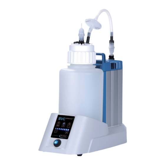
Fuse holder On / Off switch Touch panel Rating plate Outlet Connection tubing Hydrophobic protection filter Connection filter Connection VacuuHandControl VHC Closing screw (optional: connection second VHC Screw cap / bottle cap with insert Collection bottle Handle Level sensor BVC control... - Page 20 20 of 76 BVC control G BVC professional...
-
Page 21: On/Off Switch
page 21 of 76 BVC professional G On/off switch System switched off System switched on Attention: Operate the on/off switch only by hand. -
Page 22: Use And Operation
page 22 of 76 Use and operation First steps: Installation Unpack the equipment. Safety information for vacuum equipment Sicherheitshinweise für Vakuumgeräte Safety information for vacuum equipment Avis de sécurité pour des dispositifs à vide Указания за безопасност за вакуумни уреди 真空设备的安全信息... - Page 23 page 23 of 76 Setting up the BVC. Connect to power supply. Check line voltage and current prior to switching on! Attach tubing of the VacuuHandControl VHC to the hose nozzle of the bottle head.
-
Page 24: Operation Bvc Control / Bvc Control G
24 of 76 Operation BVC control / BVC control G The unit has a touch panel so the keys need only be touched gently. Do not press the keys! The keys “+“ and “-“ have to be touched > 0.25 seconds to be actuated. -
Page 25: Operation Bvc Professional / Bvc Professional G
page 25 of 76 Operation BVC professional / BVC professional G The unit has a touch panel so the keys need only be touched gently. Do not press the keys! The keys “+“ and “-“ have to be touched > 0.25 seconds to be actuated. The other keys have to be touched >... -
Page 26: Notes Regarding The Setting Of The Suction Power
page 26 of 76 Notes regarding the setting of the suction power Depending on ambient atmospheric pressure (depending on altitude or weather conditions) and on the vapor pressure of the media inside the collection bottle, the setting of a high underpressure (e. g., 850 mbar, 8 LEDs flash) may lead to continuous operation of the pump. -
Page 27: Level Sensor Of Bvc Professional / Bvc Professional G
page 27 of 76 Level sensor of BVC professional / BVC professional G The sensor foil is located on the bottle support. The level sensor gives an alarm and switches off the pump to avoid an overfilling of the collection bottle, if the liquid level in the collection bottle reaches the height of the level sensor, approximately 80% of the maxi- mum bottle capacity (grey marked range with bottle symbols on the sen- sor foil, both for the 2l or 4l bottle). - Page 28 28 of 76 NOTICE Use only the original VACUUBRAND BVC bottle or the original spare bot- tle (see “Accessories - Spare parts”). Do not fix adhesive foil or something near it at the bottle side next to the sensor foil or directly at the sensor foil.
-
Page 29: During Operation
page 29 of 76 During operation ➨ Attention: When removing the aspiration controller VHC liquid in the tube may leak! Adopt suitable measures to prevent the re- lease of dangerous, toxic, explosive, corro- sive, noxious or polluting fluids, vapors and gases. In such cases, use an appropriate collecting and disposal system and take pro- tective action for personnel, equipment and environment. -
Page 30: Filtration
page 30 of 76 Silencer at the outlet Attention: Dust-laden gases, deposits and con- densed solvent vapor can restrict air flow out the silencer. The resultant back pressure can lead to damage of pump bearings, diaphragms, and valves. Under those conditions, a silencer must not be used. - Page 31 page 31 of 76 The pump achieves its pumping speed, ultimate vacu- NOTICE um and vapor pumping rate only at operating temperature (after approx. 15 minutes). Prevent internal condensation, transfer of liquids or dust. The diaphragm and valves will be damaged, if liquids are transferred through the pump in significant amounts.
-
Page 32: Filter And Collection Bottle
page 32 of 76 Filter and collection bottle The hydrophobic filter retains water and aqueous solu- NOTICE tions also in the form of aerosols. When using solvents or due to evaporation of water, formation of condensate at the outlet of the BVC is possible. + Important: Comply with applicable regulations when disposing of solvents. - Page 33 33 of 76 Emptying the collection bottle of the BVC control and BVC control G Check liquid level in the collection bottle regu- max. larly. Maximum admissible liquid level in collec- tion bottle: approx. 80 %, depending on the application.
-
Page 34: Disinfection Routine
page 34 of 76 Emptying the collection bottle of the BVC professional and BVC professional G Check liquid level in the collection bottle regu- larly. Maximum admissible liquid level in collec- tion bottle: approx. 80 %, depending on the application. (In case of low boiling liquids or in case of suction of liquids which tend to foam, the admissible liquid level might be reduced.) The level sensor switches off the pump at a... - Page 35 page 35 of 76 Vent the collection bottle. atmo- spheric pressure Remove the tubing at the inlet of the pump or disconnect coupling. Remove screw cap from the collection bottle af- ter venting. Remove bottle from the support. Sterilize and dispose of collected liquid accord- ing to appropriate regulations.
-
Page 36: Cleaning And Decontaminating
page 36 of 76 Cleaning and decontaminating Over time, discoloration and material changes (e.g., re- siliency, elasticity / tightness, cracking) due to repeated steam sterilizations / autoclavings and / or chemical disin- fections may occur. Check all parts regularly. Replace defective parts. Autoclaving Autoclaving The collection bottle with bottle head and screw... -
Page 37: Disinfection
(chlorine avoid leaving residues of disinfectant in the bleach) bottle. ➨ A lternative: Use the BVC control G / BVC professional G with 2l borosilicate glass bot- tle. Attention: The quick-coupling accessory sets between the pumping unit and VHC are not suitable for use with sodium hypo- chlorite (chlorine bleach). - Page 38 page 38 of 76 + Using corrosive disinfectants may result in damage, malfunction and/or failure of the equipment. + Chlorine permeates the hydrophobic filter on top of the collection bottle and may damage the materials of the equipment or the vacuum supply. + Leaking of liquid from a damaged collection bottle or suction tube may lead to exposure of personnel and material or to damage/destruction of wetted equipment...
-
Page 39: Cleaning
page 39 of 76 Cleaning Incrustations or other deposits on the bottle wall of the BVC collection bottle may influence the alarm level of the capacitive measurement ele- ment of the level sensor of the BVC professional / BVC professional G. The level alarm may occur too early, too late or not at all. -
Page 40: Adjustment Of The Bvc Level Sensor To Work Properly With A New Bottle, Or To Correct False Alarms
+49 9342 808-5500 (after sales service), or your local VACUUBRAND sales office. NOTICE Use only the original VACUUBRAND BVC bottle or the original spare bot- tle (see “Accessories - Spare parts”). Attention: When performing an adjustment, the bottle has to be clean and free of incrustations or other deposits, see section “Cleaning”. -
Page 41: Preparation
page 41 of 76 adhesive foil NOTICE Do not attach adhesive foil or anything similar to level sensor or to the side of the bottle directly next to the sensor. Preparation Empty the bottle, decontaminate in case, clean and dry. Position the bottle in the BVC. -
Page 42: Adjustment Routine For Bvc Professional With 4L Polypropylene Bottle
V1.9, see rating plate Adjustment routine for older software versions: See “Instructions for adjust- ment of the liquid level sensor” on www.vacuubrand.com. Attention: Do not interrupt the adjustment routine once you have begun, even if there is an alarm. Complete the entire routine, and repeat if necessary. - Page 43 Switch off the BVC. Step 5 Repeat adjustment. Switch on the BVC. If adjustment is not suc- cessful after several at- The pump starts. tempts, please call +49 9342 808-5500 (after sales service), or your lo- cal VACUUBRAND sales office.
-
Page 44: Adjustment Routine For Bvc Professional With 2L Glass Bottle
V1.9, see rating plate Adjustment routine for older software versions: See “Instructions for adjust- ment of the liquid level sensor” on www.vacuubrand.com. Attention: Do not interrupt the adjustment routine once you have begun, even if there is an alarm. Complete the entire routine, and repeat if necessary. - Page 45 Switch off the BVC. Step 5 Repeat adjustment. Switch on the BVC. If adjustment is not suc- cessful after several at- The pump starts. tempts, please call +49 9342 808-5500 (after sales service), or your lo- cal VACUUBRAND sales office.
-
Page 46: Assembling Of Components
page 46 of 76 Assembling of components Replacing the filter Vent the collection bottle. Ensure that there is no liquid in the tube to avoid risk of contamination. atmospheric pressure Remove connecting tube from the filter. Re- move the filter from the piece of tube at the hose nozzle. -
Page 47: Assembling A Second Vhc
page 47 of 76 Assembling a second VHC connection set (with / without coupling) or conversion to quick coupling - bottle) Empty bottle. Decontaminate equipment if necessary. Remove filter with connection tubing from bottle head. Remove screw cap from the collection bottle. Unscrew closing screw. - Page 48 page 48 of 76 BVC with glass bottle Screw hose connection (1a) with seal ring (2) or coupling (1b) with seal ring (2) into the screw cap. Assemble hose (3) under the screw cap to the lead through. BVC with polypropylene bottle Insert hose connection (1a) with seal ring (2) or coupling (1b) with seal ring (2) in the screw cap.
-
Page 49: Assembling Quick Coupling Bottle - Pump Unit
Attention: The extension set “Quick coupling bottle - pump unit” is designated for two different extension versions. Therefore the set consists of parts which may not be necessary in each individual case. Redundant parts are not credited by VACUUBRAND. Assembling to pump inlet Remove tubing. Disassemble hose nozzle. -
Page 50: Assembling A Hose Nozzle At The Bottle Head Of The Bvc
page 50 of 76 Assembling a hose nozzle at the bottle head of the BVC Hose nozzle (638509), see “Accessories”, e.g., for filtration applications Empty bottle. Decontaminate equipment if necessary. Remove filter with connection tubing from bottle head. Remove screw cap from the collection bottle. Unscrew closing screw. -
Page 51: Quick Coupling Sets
page 51 of 76 Quick coupling sets Quick coupling set: VHC to bottle Quick coupling made of PVDF, with adapter to connect a VHC to a collection bottle. When disconnected, the collection bottle closes vac- uum tight. Quick coupling set: Bottle to pump unit Quick coupling made of PVDF, to connect a col- lection bottle to a BVC basic / basic G. -
Page 52: Accessories - Spare Parts
page 52 of 76 Accessories - spare parts Collection bottle 4L, made of PP, with protection filter and inlet tube ....635810 Collection bottle 2L glass, coated, with protection filter and inlet tube ....635809 Attention: Please order quick-couplings separately! Collection bottle 4L, made of PP, for BVC professional with quick coupling, protection filter and inlet tube ...... - Page 53 Silicone hose 9/6 mm (length in cm) ....638263 (bend protection) Extension kit second VHC connection ..699943 (to be assembled at a VACUUBRAND BVC, without , without quick coupling) Hose nozzle DN 6/10mm, thread G1/4” ..638509 For further accessories and spare parts see in-...
- Page 54 page 54 of 76 Adapter BVC for 2L glass bottle ....635839 BVC shuttle ...........696880 (mobile underframe for BVC)
-
Page 55: Troubleshooting
page 55 of 76 Troubleshooting Fault Possible cause Remedy ❑ Pump fails to start, ➨ Not plugged in, or failure ✔ Plug in, or check fuse system becomes of electrical supply? controlling power outlet. vented. ➨ Power switched off? ✔ Switch on power. ➨... - Page 56 ➨ Not using original ✔ Use original occurs too early, too VACUUBRAND BVC VACUUBRAND BVC late or not at all. bottle? bottle or original spare bottle. ➨ Adhesive foil at the col- ✔...
-
Page 57: Replacing Diaphragms And Valves
page 57 of 76 Replacing diaphragms and valves ➨ Never operate the pump if covers or other parts of the pump are disassembled. ➨ Before starting maintenance, disconnect the electri- cal power cord. Wait 5 seconds after isolating the equipment from AC power to allow the capacitors to discharge. - Page 58 page 58 of 76 Ensure that maintenance is done only by suitably NOTICE trained and supervised technicians. The valves and diaphragms as well as the motor capac- itors are wear parts. If the rated ultimate vacuum is no longer achieved or in case of increased noise level, the pump interior, the diaphragms and the valves must be cleaned and the diaphragms and valves must be checked for cracks or other damage.
-
Page 59: Cleaning And Inspecting The Pump Heads
page 59 of 76 Cleaning and inspecting the pump heads ➨ Fix cover plate at the pump housing using adhesive tape. ➨ Unscrew elbow fitting with silencer at the outlet of the pump. ➨ Depending on BVC version, remove con- nection tubing at the hose nozzle or detach quick coupling. - Page 60 page 60 of 76 ➨ Remove the cover of the housing cover from the housing. View of the disassembled pump head parts ME 1C 11 10 1: Cover of housing cover 7: Diaphragm clamping disc 2: Housing cover with square head screw 3: Housing cover insert 8: Diaphragm 4: Valves...
-
Page 61: Replacing The Diaphragm
page 61 of 76 ➨ Unscrew four screws at the pump head, pay- ing attention to washers. Remove housing cover. ➨ Unscrew union nut and remove hose from elbow fitting. Remove housing cover insert with elbow fitting. ➨ Note position of valves. + Replace valves if necessary. - Page 62 page 62 of 76 + If the old diaphragm is difficult to separate from the diaphragm support disc, immerse assembly in naphtha or petroleum ether. Do not inhale vapors! + Check for washers between the diaphragm support disc and the connecting rod. Make sure that the original number is reassembled.
-
Page 63: Assembling The Pump Head
page 63 of 76 ➨ Position any washers that are present be- tween diaphragm support disc and connec- tion rod. ➨ Screw diaphragm clamping disc, diaphragm, diaphragm support disc, and washers to con- necting rod. ➨ Bring the diaphragm into a position in which it is in contact with the housing and centered with respect to the bore so that it will become clamped uniformly between housing and... - Page 64 page 64 of 76 ➨ Put on housing cover and housing cover in- sert. + Move housing cover insert slightly to ensure that the head covers are correctly positioned. ➨ Pay attention to washers and position screws. Screw in 4 screws with washers at the hous- ing cover diagonally, loosely at first with a Torx driver T20, then tighten.
- Page 65 page 65 of 76 ➨ Position bottle in the support. ➨ Depending on BVC version, position tubing to hose nozzle or quick coupling. ➨ Screw elbow fitting with silencer to the outlet of the pump (max. 5 turns). ➨ Remove adhesive tape at the cover plate. Checking the ultimate vacuum ➨ A fter any intervention at the equipment (e.g., repair / maintenance) the ultimate vacuum of the pump has to be checked.
-
Page 66: Replacing The Fuse
page 66 of 76 Replacing the fuse ➨ Switch off the pump. ➨ Disconnect the electrical power cord before opening the terminal box. After disconnecting from power, wait 5 seconds to allow the capacitors to discharge. + Identify and eliminate the cause of failure before switch- ing on the equipment again. -
Page 67: Repair - Maintenance - Return - Calibration
3 or 4. These devices cannot be checked, maintained or re- paired. Also decontaminated devices must not returned to VACUUBRAND due to a residual risk. The same conditions apply to on-site work. No repair, maintenance, return or calibration is possi- ble unless the correctly completed health and safety clearance form is returned. - Page 68 page 68 of 76 To expedite repair and to reduce costs, please enclose a detailed description of the problem and the product’s oper- ating conditions with every product returned. If you do not wish a repair on the basis of our quotation, the device may be returned to you disassembled and at your expense.
-
Page 69: Health And Safety Clearance Form
* Contact the VACUUBRAND service absolutely before dispatching the device. ** Devices which have been in contact with biological substances of risk level 3 or 4 cannot be checked, main- tained or repaired. Also decontaminated devices must not returned to VACUUBRAND due to a residual risk. ☐... -
Page 70: Ec Declaration Of Conformity Of The Machinery
Bevollmächtigter für die Zusammenstellung der technischen Unterlagen / Person authorised to compile the technical file / Personne autorisée à constituer le dossier technique: Dr. J. Dirscherl · VACUUBRAND GMBH + CO KG · Alfred-Zippe-Str. 4 · 97877 Wertheim · Germany Wertheim, 07.07.2017 . -
Page 71: China Rohs
China RoHS DECLARATION OF CONFORMITY – China RoHS 2 VACUUBRAND GMBH + CO KG has made reasonable efforts to ensure that hazardous mate- rials and substances may not be used in its products. In order to determine the concentration of hazardous substances in all homogeneous materials of the subassemblies, a “Product Conformity Assessment”... - Page 72 (Pb), mercury (Hg), cadmium (Cd), hexavalent chromium (Cr+VI), polybrominated biphenyls (PBB), and polybrominated diphenyl ethers (PBDE). Products manufactured by VACUUBRAND may enter into further devices (e.g., rotary evaporator) or can be used together with other appliances (e.g., usage as booster pumps).
- Page 73 page 73 of 76...
- Page 74 page 74 of 76...
- Page 75 page 75 of 76...
- Page 76 Alfred-Zippe-Str. 4 · 97877 Wertheim / Germany T +49 9342 808-0 · F +49 9342 808-5555 info@vacuubrand.com · www.vacuubrand.com VACUUBRAND GMBH + CO KG - Technology for Vacuum Systems - © 2017 VACUUBRAND GMBH + CO KG Printed in Germany Manual-no.: 999263 / 07/07/2017...
Need help?
Do you have a question about the BVC control and is the answer not in the manual?
Questions and answers