
Related Manuals for Omron V680S-HMD63-ETN


Summary of Contents for Omron V680S-HMD63-ETN
- Page 1 RFID System V680S Series User’s Manual (Modbus TCP) Reader/Writer V680S-HMD63-ETN V680S-HMD64-ETN V680S-HMD66-ETN Man. No. Z339-E1-10...
-
Page 2: Notice
If you find any problems in this manual, please contact your OMRON representative. If you do so, please provide the Cat. No. that is given at the back of this manual. -
Page 3: Introduction
Section 3 Installation and Connections Section 4 Preparations for Communications Section 5 Functions Section 6 Host Communications Specifications Section 7 Browser Interface Section8 Troubleshooting Section9 Maintenance and Inspection Section10 Appendices Section11 RFID System V680S-HMD63-ETN Reader/Writer V680S-HMD64-ETN Reader/Writer V680S-HMD66-ETN Reader/Writer User's Manual... -
Page 4: Terms And Conditions Agreement
Omron’s exclusive warranty is that the Products will be free from defects in materials and workmanship for a period of twelve months from the date of sale by Omron (or such other period expressed in writing by Omron). Omron disclaims all other warranties, express or implied. - Page 5 Disclaimers 1. Performance Data Data presented in Omron Company websites, catalogs and other materials is provided as a guide for the user in determining suitability and does not constitute a warranty. It may represent the result of Omron’s test conditions, and the user must correlate it to actual application requirements. Actual performance is subject to the Omron’s Warranty and Limitations of Liability.
-
Page 6: Precautions For Safe Use
• Do not bend the Cable to a bending radius of 40 mm or less. Doing so may break the wires. • If an error is detected in the Product, immediately stop operation and turn OFF the power supply. Consult with an OMRON representative. RFID System... - Page 7 Introduction 4. Cleaning • Do not clean the Product with paint thinner, benzene, acetone, or kerosene. 5. Disposal • Dispose of the Product as industrial waste. RFID System User's Manual (Modbus TCP)
-
Page 8: Precautions For Correct Use
Introduction Precautions for Correct Use Always observe the following precautions to prevent operation failures, malfunctions, and adverse effects on performance and equipment. 1. Installation and Storage Environment Do not use or store the Product in the following locations. • Locations subject to combustible gases, explosive gases, corrosive gases, dust, dirt, metal powder, or salt •... -
Page 9: Meanings Of Symbols
Introduction Meanings of Symbols Indicates particularly important points related to a function, including precautions and application advice. Indicates page numbers containing relevant information. Indicates reference to helpful information and explanations for difficult terminology. RFID System User's Manual (Modbus TCP) -
Page 10: Table Of Contents
Introduction Table of Contents Introduction NOTICE Trademarks Terms and Conditions Agreement Precautions for Safe Use Precautions for Correct Use Meanings of Symbols Table of Contents Section 1 Product Overview Features Application Flowchart Product Specifications Data Characteristics Section 2 System Configuration System Configuration Section 3 Component Names Component Names... - Page 11 Introduction Section 6 Functions Functions Using Communication Diagnostic and the RF Analyzer Using Field Extension Mode Section 7 Host Communications Specifications Modbus Communications Protocol Message Details Initializing All Settings Section 8 Browser Interface Browser Operation Window Operation Interface Section 9 Troubleshooting Error Descriptions Errors and Indicator Status Errors and Countermeasures...
- Page 12 Introduction Chemical Resistance of the Reader/Writers and RF Tags Degree of Protection Differences in Address and Size Specifications between V680 and V680S Reader/Writers Revision History Firmware Version Update History RFID System User's Manual (Modbus TCP)
-
Page 13: Section 1 Product Overview
Section 1 Product Overview Features Application Flowchart Product Specifications Data Characteristics RFID System User's Manual (Modbus TCP) -
Page 14: Features
The integrated V680S-series Reader/Writers (V680S-HMD6@-ETN) perform communications with RF Tags according to query from a host device. Integrated Structure The controller, amplifier, and antenna are integrated into the Reader/Writer for a simple structure. Previous OMRON Models V680S Integrated Reader/Writer Reader/Writer Antenna... - Page 15 You can check the communications leeway to appropriately install the Reader/Writer and RF Tags to achieve stable operation of your OMRON RFID System. You can use communications leeway diagnosis with Reader/Writers with firmware version 2.00 or higher.
- Page 16 Section 1 Product Overview Simple Connection The highly generic Ethernet is used to connect to the host device to enable easy connection with Ethernet cable without any restrictions from the host PLC manufacturer. A Switching Hub can be used to easily connect more than one RFID System.
- Page 17 Section 1 Product Overview Easy Operation A Web server is provided so that you can easily perform setup and status monitoring by connecting to a computer, without the need for any special software. Personal computer Reader/Writer Switching Hub 24-VDC power supply You can connect a computer to the Switching Hub to easily set up the Reader/Writers and check the status of the Reader/Writers.
-
Page 18: Application Flowchart
RFID System will not be influenced by surrounding metal on the Reader/Writer or mutual interference between Reader/Writers. Installation p.68 Install the Reader/Writer with four M4 screws. V680S-HMD63-ETN: Use two screws. M4 screw M4 screw V680S-HMD64-ETN/-HMD66-ETN: Use four screws. Spring washer... - Page 19 Section 1 Product Overview Setting Reader/Writer Communications Conditions p.89 he default network settings for the Reader/Writer are listed in the following table. IP address 192.168.1.200 Subnet mask 255.255.255.0 Default gateway 192.168.1.254 Port number Port number for Web browser 7090 Change the network settings of the host device to match those of the Reader/Writer. Host Device Setting Example IP address: 192.168.1.100 Subnet mask: 255.255.255.0...
- Page 20 Section 1 Product Overview Using Communication Diagnostic to Check Communications Leeway p.119 Connect the Ethernet cable, turn ON the power supply to the Reader/Writer, and then start a Web browser on a computer. Specify the IP address of the Reader/Writer in the address field of the web browser. Enter http://192.168.1.200/ if you are using the default IP address.
- Page 21 Section 1 Product Overview Using the RF Analyzer to Check the Results of Communication Diagnostic p.123 Display the RF Analyzer View. Click the Show Button in the Details column and follow the guidance to check the probable causes and corrections. RFID System User's Manual (Modbus TCP)
- Page 22 Section 1 Product Overview In this example, the position of the Tag is corrected according to the guidance. You can check the graph display to check quantitative information on the degree of instability. When you are finished, perform the step to communicate with the RF Tag again and check to see if stable communications have been achieved.
- Page 23 Section 1 Product Overview Communications with Actual Queries p.160 The Reader/Writer can perform various types of communications with RF Tags. Name Description Page READ DATA Reads data from an RF Tag in the communications field. p.160 WRITE DATA Writes data to an RF Tag in the communications field. p.161 READ ID Reads the ID code from an RF Tag in the communications field.
- Page 24 Section 1 Product Overview If you Encounter a Problem... Troubleshooting p.157 Exception Code Table p.61 Operation Indicators p.239 Troubleshooting Flowcharts RFID System User's Manual (Modbus TCP)
-
Page 25: Product Specifications
Description of Regulations and Standard Standard Standard IP address label IP address label IP address label Ferrite core Note 1. Oil resistance has been tested using a specific oil as defined in the OMRON test method. RFID System User's Manual (Modbus TCP) - Page 26 Section 1 Product Overview Dimensions V680S-HMD63-ETN (Unit: mm) Two, 4.5-dia. Nameplate Seven, operation indicators mounting holes Standards label 42±0.2 Two, M4 holes M12×1 Mount Hole Dimensions 37.5 Connector V680S-HMD64-ETN (Unit: mm) Seven, Operation Indicators Four, 4.5-dia. Nameplate...
- Page 27 Section 1 Product Overview V680S-HMD66-ETN (Unit: mm) Nameplate Mounting Hole Dimensions Operation Indicators Standards label 110±0.2 Four, M4 holes M12 threaded section Four, 4.5-dia. mounting holes Connector RFID System User's Manual (Modbus TCP)
- Page 28 Section 1 Product Overview Extension Cable General Specifications Item Model V680S-A40@M V680S-A50@M Type Special connector--Special connector Length 10 m 20 m 50 m 10 m 20 m Cable diameter 8 (number of conductors: 7) Insulation resistance 20 MΩ min. (at 500 VDC) between cable terminals and sheath Dielectric strength 1,000 VAC, 50/60 Hz for 1 min between cable terminals and sheath Standards...
- Page 29 Section 1 Product Overview Cables General Specifications Item Model V680S-A41@M V680S-A51@M V680S-A42@M Type Special connector--RJ45 Special connector--Loose wires Length 10 m 10 m 10 m Cable diameter 8 (number of conductors: 7) Insulation resistance 20 MΩ min. (at 500 VDC) between cable terminals and sheath Dielectric strength 1,000 VAC, 50/60 Hz for 1 min between cable terminals and sheath Standards...
- Page 30 Section 1 Product Overview V680S-A42@M (Unit: mm) (50) 40.7 (50) CONNECTOR VINYL INSULATED ROUND CODE 8 dia. LABEL TYPE L LENGTH +150 V680S-A42 2M 2,000 +300 V680S-A42 5M 5,000 +1000 V680S-A42 10M 10,000 RFID System User's Manual (Modbus TCP)
- Page 31 Note 1. After storing RF Tags at high temperatures, rewrite the data even if changes are not required. High temperatures are those between 125 and 180°C. 2. Oil resistance has been tested using a specific oil as defined in the OMRON test method. Dimensions (Unit: mm) 1.1 2.7±0.1...
- Page 32 Section 1 Product Overview V700-A80 Attachment (Unit: mm) Mounting Hole Dimensions Two, M3 holes 31±0.2 31±0.2 Materials PPS resin RF Tag Heat Resistance • Storing RF Tags under high temperatures or under heat cycles will adversely affect the performance of the internal parts and the service life of the RF Tags.
- Page 33 Note 1. After storing RF Tags at high temperatures, rewrite the data even if changes are not required. High temperatures are those between 125 and 180°C. 2. Oil resistance has been tested using a specific oil as defined in the OMRON test method. The V680-D1KP66MT must be mounted on a metallic surface. The markings on the V680-D1KP66T and V680-D1KP66MT are shown below.
- Page 34 Section 1 Product Overview Dimensions V680-D1KP66T/-D1KP66MT (Unit: mm) Four, 4-mm corners Mounting Hole Dimensions Four, 3-mm corners +0.2 Two, M3 holes +0.2 +0.2 Two, 3.5 dia. Two, 6 dia. +0.2 +0.1 Case material PPS resin V600-A86 Attachment (Unit: mm) Four, 5.5-mm corners Two, 4 dia.
- Page 35 Section 1 Product Overview V680-D1KP66T-SP General Specifications Item Model Specification Compliance standards ISO/IEC 18000-3 (15693) Memory capacity 1,000 bytes Memory type EEPROM Data retention 10 years (85°C or less) Write endurance 100,000 writes for each block (25°C) Ambient operating -25 to 70°C (with no icing) temperature Ambient operating...
- Page 36 Note1. After storing RF Tags at high temperatures, rewrite the data even if changes are not required. High temperatures are those between 125 and 250°C. 2. Oil resistance has been tested using a specific oil as defined in the OMRON test method. Dimensions V680-D1KP58HTN 10±0.2...
- Page 37 Section 1 Product Overview V680-A80 Attachment This Attachment is used to hold V680-D1KP58HTN ID Tags. Applicable model: V680-D1KP58HTN (Unit: mm) 20 dia. 12 dia. 3.2 dia. 11.5 Mounting Hole Dimensions Accessories: 2 nuts (M12) 1 split pin (nominal dimensions: 3.2-mm dia. × 20-mm length) ...
- Page 38 Section 1 Product Overview Data Retention Time Reset Procedure Always use the following procedure to reset the data holding time before a total of 10 hours is reached. When Using RF Tag Memory Addresses 0010 to 0015 hex 1. Read the data from RF Tag addresses 0010 to 0015 hex. RF Tag Memory 0010 Read the memory addresses...
- Page 39 Note 1. The number of accesses is the total number of reads and writes. 2. Oil resistance has been tested using a specific oil as defined in the OMRON test method. The V680-D8KF67M must be mounted on a metallic surface. The markings on the V680-D8KF67 and V680-D8KF67M are shown below.
- Page 40 Section 1 Product Overview Dimensions V680-D8KF67/-D8KF67M (Unit: mm) 13.2 Mounting Hole Dimensions Two, 3.5-dia. Two, M3 holes mounting holes 13.2 40+0.1 -0.5 32±0.2 Mounting reference surface 32±0.2 40+0.1 -0.5 Case material PBT resin Filling Epoxy resin RFID System User's Manual (Modbus TCP)
- Page 41 Metal countermeasures None Note 1. The total communications frequency of the Read or Write is called an access frequency. 2. Oil resistance has been tested using a specific oil as defined in the OMRON test method. Dimensions V680-D8KF68A (Unit: mm) Two, 4.5-dia.
- Page 42 Note 1. The number of accesses is the total number of reads and writes. 2. Oil resistance has been tested using a specific oil as defined in the OMRON test method. The V680S-D2KF67M/-D8KF67M must be mounted on a metallic surface. The markings on the V680- D2KF67/-D8KF67 and V680-D2KF67M/-D8KF67M are shown below.
- Page 43 Section 1 Product Overview Dimensions V680S-D2KF67/-D2KF67M/-D8KF67/-D8KF67M (Unit: mm) Two, 3.5-dia. mounting holes Mounting Hole Dimensions 2-M3 32±0.2 32±0.2 Case material PPS resin RFID System User's Manual (Modbus TCP)
- Page 44 Note 1. The number of accesses is the total number of reads and writes. 2. Oil resistance has been tested using a specific oil as defined in the OMRON test method. The V680S-D2KF68M/-D8KF68M must be mounted on a metallic surface. The markings on the V680- D2KF68/-D8KF68 and V680-D2KF68M/-D8KF68M are shown below.
- Page 45 Section 1 Product Overview Dimensions V680S-D2KF68/-D2KF68M/-D8KF68/-D8KF68M (Unit: mm) Two, 4.5-dia. mounting holes Mounting Hole Dimensions 2-M4 76±0.2 76±0.2 Case material PPS resin RFID System User's Manual (Modbus TCP)
-
Page 46: Data Characteristics
Section 1 Product Overview Data Characteristics Communications Range Specifications V680S-HMD63-ETN Reader/Writer RF Tag Communications distance specification V680S-HMD63- V680-D1KP54T (mounted to non-metallic material) Read 0.0 to 24.0 mm (axis offset: ±10 mm) ETN (mounted to Write 0.0 to 20.0 mm (axis offset: ±10 mm) - Page 47 Section 1 Product Overview Installation Conditions V680-D1KP54T V680-D1KP66T V680S-HMD63-ETN V680S-HMD63-ETN Metallic material Metallic material V680-D1KP66T V680-D1KP54T Communications range Communications range Non-metallic material Non-metallic material Non-metallic material Non-metallic material (Examples: Resin, plastic, wood, etc.) (Examples: Resin, plastic, wood, etc.) (Examples: Resin, plastic, wood, etc.) (Examples: Resin, plastic, wood, etc.)
- Page 48 Section 1 Product Overview V680S-HMD64-ETN Reader/Writer RF Tag Communications Range Specification Read 5.0 to 50.0 mm (axis offset: ±10 mm) V680S-HMD64-ETN V680-D8KF67 (mounted to metallic material) (mounted to non-metallic material) Write 5.0 to 50.0 mm (axis offset: ±10 mm) Read 3.0 to 40.0 mm (axis offset: ±10 mm) V680-D8KF67M (mounted to metallic material)
- Page 49 Section 1 Product Overview Installation Conditions V680-D8KF67 V680-D8KF67M Metallic material V680S-HMD64-ETN Metallic material V680S-HMD64-ETN Metallic material V680-D8KF67 V680-D8KF67M Communications Communications range range Non-metallic material Non-metallic material Non-metallic material Non-metallic material (Examples: Resin, plastic, wood, etc.) (Examples: Resin, plastic, wood, etc.) (Examples: Resin, plastic, wood, etc.) (Examples: Resin, plastic, wood, etc.) V680-D8KF68/-D8KF68A...
- Page 50 Section 1 Product Overview V680-D1KP54T V680-D1KP66T Metallic material V680S-HMD64-ETN Metallic material V680S-HMD64-ETN V680-D1KP66T V680-D1KP54T Communications Communications range range Non-metallic material Non-metallic material Non-metallic material Non-metallic material (Examples: Resin, plastic, wood, etc.) (Examples: Resin, plastic, wood, etc.) (Examples: Resin, plastic, wood, etc.) (Examples: Resin, plastic, wood, etc.) V680-D1KP66M V680-D1KP66T-SP...
- Page 51 Section 1 Product Overview V680S-HMD66-ETN Reader/Writer RF Tag Communications Range Specification Read 7.0 to 70.0 mm (axis offset: ±10 mm) V680S-HMD66-ETN V680-D8KF67 (mounted to metallic material) (mounted to non-metallic material) Write 7.0 to 70.0 mm (axis offset: ±10 mm) Read 4.0 to 45.0 mm (axis offset: ±10 mm) V680-D8KF67M (mounted to metallic material)
- Page 52 Section 1 Product Overview Installation Conditions V680-D8KF67 V680-D8KF67M Metallic material V680S-HMD66-ETN Metallic material V680S-HMD66-ETN Metallic material V680-D8KF67 V680-D8KF67M Communications Communications range range Non-metallic material Non-metallic material Non-metallic material Non-metallic material (Examples: Resin, plastic, wood, etc.) (Examples: Resin, plastic, wood, etc.) (Examples: Resin, plastic, wood, etc.) (Examples: Resin, plastic, wood, etc.) V680-D8KF68/-D8KF68A...
- Page 53 Section 1 Product Overview V680-D1KP54T V680-D1KP66T Metallic material V680S-HMD66-ETN Metallic material V680S-HMD66-ETN V680-D1KP66T V680-D1KP54T Communications Communications range range Non-metallic material Non-metallic material Non-metallic material Non-metallic material (Examples: Resin, plastic, wood, etc.) (Examples: Resin, plastic, wood, etc.) (Examples: Resin, plastic, wood, etc.) (Examples: Resin, plastic, wood, etc.) V680-D1KP66MT V680-D1KP66T-SP...
- Page 54 Section 1 Product Overview MEMO RFID System User's Manual (Modbus TCP)
-
Page 55: Section 2 System Configuration
Section 2 System Configuration System Configuration RFID System User's Manual (Modbus TCP) -
Page 56: System Configuration
Section 2 System Configuration System Configuration One Reader/Writer is connected to the Host device (e.g., PLC) Reader/Writer (V680S-HMD6 -ETN) Host device (e.g., PLC) RF Tag (V680 Series and V680S Series) Cable (V680S-A40 M/-A41 M/-A42 M/-A50 M/-A51 M) 24-VDC power supply Use a device supporting STP cables for the host device (such as a Switching Hub or PLC) which is connected the specified Cables (V680S-A41 @M/-A42 @M/-A51 @M). - Page 57 Section 2 System Configuration The plural Reader/Writer’s are connected to the Host device (e.g., PLC) Host device (e.g., PLC) Reader/Writer Reader/Writer (V680S-HMD6 -ETN) (V680S-HMD6 -ETN) RF Tag RF Tag (V680 Series and V680S Series) (V680 Series and V680S Series) Cable (V680S-A40 M/-A41 M/-A42 M/-A50 M/-A51 M) Ethernet cable 24-VDC...
- Page 58 (V680 Series and V680S Series) Switching Hub (Recommended: W4S1-05C Switching Hub from OMRON) Ethernet cable Cable (V680S-A40 M/-A41 M/-A42 M/-A50 M/-A51 M) Use a device supporting STP cables for the host device (such as a Switching Hub or PLC) which is connected the specified Cables (V680S-A41 @M/-A42 @M/-A51 @M).
- Page 59 Section 2 System Configuration About the Ethernet communication abnormality If an Ethernet network is configured into a loop as shown below, broadcast packets are accumulated in the band, and the communication is disabled. Therefore, do not configure the Ethernet network into a loop. Sending broadcast storm Reader/Writer Broadcast storm...
- Page 60 Section 2 System Configuration MEMO RFID System User's Manual (Modbus TCP)
-
Page 61: Section 3 Component Names
Section 3 Component Names Component Names RFID System User's Manual (Modbus TCP) -
Page 62: Component Names
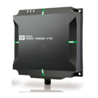
Section 3 Component Names Component Names Reader/Writer V680S-HMD63-ETN V680S-HMD64-ETN LINK/ACT LINK/ACT NORM/ERR NORM/ERR NORM/ERR NORM/ERR NORM/ERR NORM/ERR NORM/ERR NORM/ERR Connector Connector V680S-HMD66-ETN LINK/ACT NORM/ERR NORM/ERR NORM/ERR NORM/ERR Connector RFID System User's Manual (Modbus TCP) - Page 63 Section 3 Component Names Operation Indicators RUN Status Meaning green Lighting while the Reader/Writer is operating normally. Flashing Flash while the Reader/Writer is operating in Safe mode. green Flashing Flashes quickly during Reader/Writer initialization. (Flashes at 200-ms intervals.) green quickly yellow...
- Page 64 Section 3 Component Names Cables V680S-A40 @M / -A50 @M Reader/Writer connector Cable connector Reader/Writer connector This connector connects to the connector on the Reader/Writer. Cable Connector This connector connects to the Reader/Writer connector on the V680S-A41@M / -A42@M / -A51@M Cable.
- Page 65 Section 3 Component Names V680S-A42 @M Ethernet connector lines Reader/Writer connector Reader/Writer connector This connector connects to the connector on the Reader/Writer or to the V680S-A40 @M Extension Cable. Ethernet Connector Lines These lines are connected to an Ethernet connector to supply power and the control signal to the Reader/Writer.
- Page 66 Section 3 Component Names RF Tag The model numbers of the RF Tags that can communicate with the Reader/Writer are given in this section. For the communications range specifications, refer to Communications Range Specifications in Section 1 Product Overview. p.44 (Unit: mm) ...
- Page 67 Section 3 Component Names (Unit: mm) V680-D8KF67/-D8KF67M Shape: 40 × 40 × 4.5 (W × H × D) V680-D8KF68A Shape: 86 × 54 × 10 (W × H × D) V680S-D2KF67/-D2KF67M/-D8KF67/-D8KF67M Shape: 40 × 40 × 5 (W × H × D) ...
- Page 68 Section 3 Component Names MEMO RFID System User's Manual (Modbus TCP)
-
Page 69: Section 4 Installation And Connections
Section 4 Installation and Connections Installation Connections and Wiring RFID System User's Manual (Modbus TCP) -
Page 70: Installation
Section 4 Installation and Connections Installation Reader/Writer V680S-HMD63-ETN Install the Reader/Writer with two M4 screws. Use both spring washers and flat washers M4 screw Spring washer Mounting Hole Dimensions Flat washer Two, M4 holes 42±0.2 (Unit: mm) When you install the Reader/Writer, prepare the metal plate shown in the following figure. - Page 71 Section 4 Installation and Connections V680S-HMD64-ETN Install the Reader/Writer with four M4 screws. Use both spring washers and flat washers. M4 screw Spring washer Flat washer Mounting Hole Dimensions Four, M4 holes 65±0.2 (Unit: mm) When you install the Reader/Writer, prepare the metal plate shown in the following figure. When the metal plates size is larger than the below illustration, communication range will change.
- Page 72 Section 4 Installation and Connections V680S-HMD66-ETN Install the Reader/Writer with four M4 screws. Use both spring washers and flat washers. M4 screw Spring washer Mounting Hole Dimensions Flat washer Four, M4 holes 110±0.2 (Unit: mm) When you install the Reader/Writer, prepare the metal plate shown in the following figure. When the metal plates size is larger than the below illustration, communication range will change.
- Page 73 Section 4 Installation and Connections RF Tag V680-D1KP54T Either use the V700-A80 Attachment to mount the RF Tags with screws or permanently attach the RF Tags with adhesive. Installation with the V700-A80 Attachment Place the V680-D1KP54T RF Tag in the Attachment. The V680-D1KP54T RF Tag can be placed in the Attachment in either direction.
- Page 74 Section 4 Installation and Connections V680-D1KP66T Mounting on Non-metallic Material Mount the RF Tag using M3 flat-head screws Mounting Hole Dimensions from the marked side. Two, M3 holes Tighten the screws to a torque of 0.3 to 0.5 N·m. M3 flat-head screw ±0.2 Marked side...
- Page 75 Section 4 Installation and Connections V680-D1KP66MT Mount the RF Tag using M3 flat-head screws Mounting Hole Dimensions from the marked side. Two, M3 holes Tighten the screws to a torque of 0.3 to 0.5 N·m. M3 flat-head screw ±0.2 Marked side ±0.2 When you install the RF tag, prepare the metal plate as shown in the figure below.
- Page 76 Section 4 Installation and Connections V680-D1KP66T-SP Mount the RF Tag using M5 screws and washers. The tightening torque is 1.2 N·m. There are no restrictions on the mounting direction for the RF Tag or the direction of RF Tag travel in respect to the Reader/Writer.
- Page 77 Section 4 Installation and Connections V680-D1KP58HTN Use the following procedure to install an RF Tag with the V680-A80 Attachment. Attach the Attachment to the workpiece. Mounting Hole Dimensions Tighten the lock nut. · Use a tightening torque of 21 to 42 N Place the RF Tag in the Attachment.
- Page 78 Section 4 Installation and Connections V680-D8KF67 Mount the RF Tag with M3 screws. Mounting Hole Dimensions Two, M3 holes Tighten the screws to a torque of 0.6 N·m. M3 screw ±0.2 Marked side ±0.2 Refer to RF Tag Installation Precautions in Section 11 Appendices for information on the effect of metal at the back surface, Mutual Interference of RF Tags and Influence of Inclination of the V680-D8KF67.
- Page 79 Section 4 Installation and Connections V680-D8KF68A Mount the RF Tag with M4 screws. Tighten the screws to a torque of 0.7 to 1.2 N·m. Two, M4 holes M4 screw Spring washer Flat washer Marked side (Unit: mm) Refer to RF Tag Installation Precautions in Section 11 Appendices for information on the effect of metal at the back surface, Mutual Interference of RF Tags and Influence of Inclination of the V680-D8KF68A.
- Page 80 Section 4 Installation and Connections V680S-D2KF67/-D8KF67 Mount the RF Tag with M3 screws. Mounting Hole Dimensions Two, M3 holes Tighten the screws to a torque of 0.6 N·m. M3 screw ±0.2 Marked side ±0.2 Refer to RF Tag Installation Precautions in Section 11 Appendices for information on the effect of metal at the back surface, Mutual Interference of RF Tags and Influence of Inclination of the V680S-D2KF67.
- Page 81 Section 4 Installation and Connections V680S-D2KF68/-D8KF68 Mount the RF Tag with M4 screws. Tighten the screws to a torque of 0.7 to 1.2 N·m. Two, M4 holes M4 screw Spring washer Flat washer Marked side (Unit: mm) Refer to RF Tag Installation Precautions in Section 11 Appendices for information on the effect of metal at the back surface, Mutual Interference of RF Tags and Influence of Inclination of the V680S-D2KF68.
-
Page 82: Connections And Wiring
Section 4 Installation and Connections Connections and Wiring Connecting and Removing the Reader/Writer Cable Connecting Method Hold the connector on the Cable and insert it into the connector on the Reader/Writer. Do not apply 30 N or more power to the connector of the Reader/Writer. - Page 83 Section 4 Installation and Connections Removal Method Turn the Cable connector counterclockwise to release the lock. Hold the base of the Cable connector and pull it straight out. If the connector is difficult to remove, press on the Reader/Writer and pull on the connector. Never pull on the Cable with excessive force.
- Page 84 Section 4 Installation and Connections Attaching Ferrite Core If you use the V680S-HMD66-ETN, attach the ferrite core that is provided with the Reader/Writer to the V680S-A41M/-A42M/-A51M Cable. You do not need to attach a V680S-A40M/-A50M Extension Cable. V680S-A41 / -A51 Power supply lines: Brown (+24V),Blue(0V) Control signal line: Purple Ferrite core...
- Page 85 Section 4 Installation and Connections Connecting the V680S-A41@M/-A51@M Cable to the Host Device Power Supply and Operation Mode Signal You must connect the power supply lines (24 VDC and 0 VDC) and the operation mode signal line in the V680S-A41@M/-A51@M Cable. Wire color Meaning Connected to...
- Page 86 Section 4 Installation and Connections Extending the Cable Connecting Method Insert the connector on the V680S-A41@M/- A51@M Cable into the connector on the V680S- A40@M/-A50@M Extension Cable. Turn the connector on the V680S-A41@M/- A51@M Cable clockwise to lock it in place. Recommended tightening torque: 0.39 to 0.49 N·m RFID System User's Manual...
- Page 87 Section 4 Installation and Connections Assembling and Connecting the V680S-A42@M Cable and Connector Assembly Method Follow the table below, assemble the connector. Prepare the shielded-connectors according to the application. Wire color Name Function Applicable wire Brown +24V AWG20 (Drain wire) Frame ground Purple CONT...
- Page 88 Section 4 Installation and Connections MEMO RFID System User's Manual (Modbus TCP)
-
Page 89: Section 5 Preparations For Communications
Section 5 Preparations for Communications Starting the Reader/Writer Setting Communications Conditions RFID System User's Manual (Modbus TCP) -
Page 90: Starting The Reader/Writer
Section 5 Preparations for Communications Starting the Reader/Writer Reader/Writer Starting Procedure Connect the Cable to the Reader/Writer. Refer to Connecting and Removing the Reader/Writer Cable in Section 4 Installation and Connections for the connector method. p.80 Connect the power supply lines and the operation mode signal line in the Cable to the power source and connect the RJ45 connector to an Ethernet port on the host device. -
Page 91: Setting Communications Conditions
Section 5 Preparations for Communications Setting Communications Conditions Initial Setting Procedure Default TCP/IP Network Settings in the Reader/Writer The default network settings for the Reader/Writer are listed in the following table. Change the network settings of the host device to match those of the Reader/Writer. IP address 192.168.1.200 Subnet mask... - Page 92 Section 5 Preparations for Communications Setting Procedure for Modbus Queries from the Host Device You can set the following items with a SET TCP/IP COMMUNICATIONS CONDITIONS query. • IP address • Subnet mask • Gateway address Refer to SET TCP/IP COMMUNICATIONS CONDITIONS in Section 7 Host Communications Specifications for the setting method for Modbus queries from the host device.
- Page 93 Section 6 Functions Functions Using Communication Diagnostic and the RF Analyzer 119 Using Field Extension Mode RFID System User's Manual (Modbus TCP)
- Page 94 Section 6 Functions Functions Operation Mode The Reader/Writer has two operation modes: Run Mode, and Safe Mode. You can use the control signal to the Reader/Writer connector to change between these modes. Run Mode When you connect the control signal to the 24-VDC side of the power supply and turn ON the power supply, the Reader/Writer will start in Run Mode.
- Page 95 Section 6 Functions RF Tag Communications Communications Options Communications with the RF Tag are performed according to one of the communications options that are listed in the following table. The setting of the communications option is effective immediately after it is changed. It is saved in internal memory in the Reader/Writer even after the power supply is turned OFF.
- Page 96 Section 6 Functions Once Communications with the RF Tag are performed according to queries that are sent from the host device. When the Reader/Writer has completed communicating with the RF Tag, it sends a response to the host device and then waits for another query. If there is no RF Tag in the communications field when the Reader/Writer receives a query from the host device, the Reader/Writer returns an RF Tag missing error (error code: 2001 hex).
- Page 97 Section 6 Functions After communicating with an RF Tag, access to that RF Tag is prohibited. The Reader/Writer sends a response to the host device and then waits for another query. The Reader/Writer communicates in turn with each of the RF Tags that enters the communications field.
- Page 98 Section 6 Functions The FIFO Trigger detects the RF tag in the sequence of “RF tag detection processing” and executes read / write with the RF tag detected in the sequence of “communication processing”. <Without ID code check> When using FIFO Trigger (Without ID code check), please do not put the next RF tag B in the communication area until communication with the detected RF tag is completed.
- Page 99 Section 6 Functions Normal RF Tag Communications Communications with the RF Tag are performed by using the queries that are listed in the following table. Name Description Page READ DATA Reads data from an RF Tag. p.160 WRITE DATA Writes data to the memory of the RF Tag.
- Page 100 Section 6 Functions RF TAG OVERWRITE COUNT CONTROL Query with an Addition Specification The overwrite count control area consists of 4 bytes from the specified start address. The increment value is added to the overwrite count and then written to this area. When the value reaches 100,000 (i.e., 0186A0 hex), a warning code is returned.
- Page 101 Section 6 Functions Reader/Writer Controls STOP Query This query is used to cancel or abort auto communications operation and fifo communications operation. Host device Reader/Writer STOP Host device Reader/Writer Response Communications Reader/Writer operation Query standby status processing RESET Query This query is used to make the Reader/Writer reset itself.
- Page 102 Section 6 Functions Maintenance Noise monitor Communication performance will be reduced when the RF tag or the Reader/Writer are influenced by ambient noise. The Reader/Writer responds the ambient noise level by using noise monitor function. The response data includes the following parameters. By checking the noise level, you can check the influence on the performance of communication with the RF tag in advance.
- Page 103 Section 6 Functions Setting Queries You can use setting queries to set the operating conditions of the Reader/Writer according to the application environment. You can save the settings so that they are stored in internal memory in the Reader/Writer even after the power supply is turned OFF.
- Page 104 Section 6 Functions SET TAG COMMUNICATIONS CONDITIONS Query This query sets parameters that are related to the operation of communications with RF Tags. Any changes to the settings that are made with this query are effective immediately. (There is no need to reset the Reader/Writer to save the settings.) ...
- Page 105 Section 6 Functions Setting Host Device Communications Conditions You can set parameters for communications between the Reader/Writer and host device. If you change any of these settings, you must first save them and then reset the Reader/Writer to enable using them. ...
- Page 106 Section 6 Functions Error Logs The Reader/Writer manages errors that occur during operation in logs. The error logs are saved until the power supply to the Reader/Writer is turned OFF. You can read the error logs by sending queries from the host device or by using a browser. The following logs are saved.
- Page 107 Section 6 Functions Communications Error Log Each record in the communications error log consists of 24 bytes in the format that is shown in the following table. Up to eight records are recorded. To read the communication error log, either send a GET COMMUNICATIONS ERROR LOG query or read it from a browser.
- Page 108 Section 6 Functions Recent Error Query Log The record in the recent error query log consists of 250 bytes in the format that is shown in the following table. Only one record is ever recorded in the recent error query log. To read the recent error query log, either send a GET RECENT ERROR QUERY INFORMATION query or read it from a browser.
- Page 109 Section 6 Functions Web Server The following functions are provided in the Web server interface. Status Monitoring, Setting, and Confirmation Status Monitoring You can monitor the status of the Reader/Writer. The Reader/Writer status includes the firmware versions, MAC address, network settings, operating status, and other status information. ...
- Page 110 Section 6 Functions RFID System Maintenance Communications performance can be affected by environmental factors around the RFID System (including metal objects, the positional relationship between the Reader/Writer and RF Tags, and noise). You can use the RFID System maintenance functions to check the leeway in communications and achieve more stable device operation.
- Page 111 Section 6 Functions Communication diagnostic is disabled in the default settings. To use communication diagnostic, you must enable it in advance. Refer to RF Tag Communications View in Section 8 Browser Interface for the setting procedure for communication diagnostic. p.215 Use the results of communication diagnostic as a guideline.
- Page 112 Section 6 Functions You can use communication diagnostic to detect and diagnoses deterioration of performance for the following conditions. Communications performance reduced by inclination of Communications performance reduced by positional RF Tags offset of RF Tags Communications performance reduced by metal objects Communications performance reduced by an excessively long communications ranges Metal...
- Page 113 Section 6 Functions RF Analyzer The RF Analyzer displays detailed information from communication diagnostic on a web browser. You can easily check to see how stable communications are and troubleshoot problems. You can browse a list of diagnostic information and periodically confirm the leeway quantitatively on graphs.
- Page 114 Section 6 Functions An application example of the RFID System maintenance functions is given below. Enable communication diagnostic. p.18 Communicate with an RF Tag. p.17 If the operation indicator lights in yellow, check the RF Analyzer on a web browser. p.18 Check the probable causes and corrections with the RF Analyzer and implement suitable measures.
- Page 115 Section 6 Functions Multi-Reader/Writer Operation There are two modes that you can use for multi-Reader/Writer operation: Field Extension Mode and High-speed Traveling Mode. You can link up to eight Reader/Writers to perform communications operations with RF Tags. One of the Reader/Writers operates as the master and the other Reader/Writers operate as slaves. The host device just has to control one Reader/Writer, the master, to easily achieve complex control operations for all of the linked Reader/Writers.
- Page 116 Section 6 Functions The RF Tag communications queries that you can use during multi-Reader/Writer operation (Field Extension Mode or High-speed Traveling Mode) are shown in the following table. If you use unsupported RF Tag communications queries when multi-Reader/Writer operation is enabled, an execution status error will be indicated in the response.
- Page 117 Section 6 Functions Name Supported Name Supported RF Tag READ DATA Checking MEASURE NOISE communications Reader/Writer WRITE DATA GET MODEL information INFORMATION READ ID GET FIRMWARE VERSION COPY DATA GET MAC ADDRESS DATA FILL GET READER/WRITER LOCK OPERATING STATUS RF TAG OVERWRITE GET OPERATING TIME COUNT CONTROL GET RECENT ERROR...
- Page 118 Section 6 Functions Field Extension Mode You can use this mode to link Reader/Writers in order to extend the effective communications field of a Reader/Writer. Even if the workpieces are not all the same height or not oriented in the same direction, the placement of more than one Reader/Writer enables communicating with the RF Tags without worrying about the positions or orientation of the RF Tags.
- Page 119 Section 6 Functions High-speed Traveling Mode You can read large data sizes from RF Tags because the data is split up and read by more than one Reader/Writer on a time-sharing basis while the workpiece is moving. We recommend that you use this mode when reading data from RF Tags that are moving on a production line.
- Page 120 Section 6 Functions In High-speed Traveling Mode, you can use only the READ DATA RF Tag communications query. Also, you can specify only the Auto communications option. If you use any communications option other than Auto in the High-speed Traveling Mode, an execution status error will be indicated in the response. Applicable RF Tag Communications Queries Supported READ DATA...
- Page 121 Section 6 Functions Using Communication Diagnostic and the RF Analyzer You can use communication diagnostic from the Web server or with Modbus queries. Use either of the following procedures. Use the Web server to use the RF Analyzer. Using the Web Server ...
- Page 122 Section 6 Functions Select the Enable Option for Communications Diagnostic and click the Set Button. Refer to Communications Settings View in Section 8 Browser Interface for the setting procedure for the web browser interface. p.213 When you enable communication diagnostics, the setting will be retained after the Reader/Writer is restarted and communication diagnostic will remain enabled.
- Page 123 Section 6 Functions Communicating with an RF Tag The RF Tag Communications View will be displayed. Place a RF Tag in front of the Reader/Writer. To increase the accuracy of communication diagnostic, we recommend installation in an environment that is as close as possible to the actual application environment.
- Page 124 Section 6 Functions Set the communications parameters (register number, data size, etc.), click the Send Button, and check the diagnostic results. RFID System User's Manual (Modbus TCP)
- Page 125 Section 6 Functions Checking with the RF Analyzer and Implementing Corrections Display the RF Analyzer View. You cannot use communication diagnostic if you are using the FIFO Trigger communications option. Use the once or auto communications option. Click the Show Button in the Details column and follow the guidance to check the probable causes and corrections.
- Page 126 Section 6 Functions In this example, the position of the Tag is corrected according to the guidance. You can check the graph display to check quantitative information on the degree of instability. When you are finished, perform the step to communicate with the RF Tag again and check to see if stable communications have been achieved.
- Page 127 Section 6 Functions Using Modbus Queries for Communication Diagnostic Refer to the following flowchart to use Modbus queries. Enabling Communication Diagnostic p.125 Communicating with an RF Tag p.125 Getting Communications Diagnostic Results p.126 Enabling Communication Diagnostic Use the SET COMMUNICATION DIAGNOSTIC query to enable communication diagnostic. ...
- Page 128 Section 6 Functions Getting Communications Diagnostic Results Use the GET COMMUNICATIONS DIAGNOSTIC INFORMATION query to get the diagnostic results. Query Format Byte 0 Byte 1 Byte 2 Byte 3 Byte 4 Byte 5 Byte 6 Byte 7 Byte 8 Byte 9 Byte 10 Byte 11...
- Page 129 Section 6 Functions Parameter Size Description Send power level 2 bytes Contains the send power level for communication diagnostic in 4-digits hexadecimal. 0 to 10 • This is the corrected lowest value of DAC (10-bit) where communications with the RF Tag were successful out of the multiple send power levels.
- Page 130 Section 6 Functions Using Field Extension Mode Using Field Extension Mode Use the following procedure for operation in Field Extension Mode. The following figure shows an example in which four Reader/Writers are installed. Slave Reader/Writer No. 1 IP:192.168.1.201 Master Reader/Writer IP:192.168.1.200 Switching Hub IP:192.168.1.203...
- Page 131 Section 6 Functions Enabling Field Extension Mode Connect all of the Reader/Writers with Ethernet Cables and turn ON the power supplies. Set a unique IP address for each Reader/Writer in advance. Refer to Section 5 Preparations for Communications. Start a Web browser on your computer. In the address field on the Web browser operation window, enter the IP address of the Master Reader/ Writer (here, 192.168.1.200).
- Page 132 Section 6 Functions Display the Multi-Reader/Writer Settings View. Select the Field Extension Mode Check Box. Set the IP addresses of the three Slave Reader/Writers and click the Set Button. RFID System User's Manual (Modbus TCP)
- Page 133 Section 6 Functions A confirmation message will be displayed. Click the OK Button. Click the Reboot Button. A Confirm Reboot Dialog Box will be displayed. Click the Yes Button. Click this button to reboot Click this button to cancel the Reader Writer. rebooting the Reader Writer.
- Page 134 Section 6 Functions The following dialog box is displayed after reconnecting to the Reader/Writer. Click the OK Button. When re-connection goes wrong and an error message is displayed, check connection with the Reader/Writer and reboot a browser. When the Master Reader/Writer is restarted, group registration processing is automatically performed for the registered Slave Reader/Writers.
- Page 135 Section 6 Functions Executing a READ DATA Query in Field Extension Mode When the RF Tag Communications Option of the Master Reader/Writer Is Set to Once Send a READ DATA query from the host device to the Master Reader/Writer. Slave Reader/Writer No.
- Page 136 Section 6 Functions Slave Reader/Writer No. 1 will communicate with the RF Tag using the Once communications option. Here, communications will end normally or an RF Tag communications error will occur, the Reader/ Writer will return a response to the host device, and processing will end. If an RF Tag tag missing error is detected, processing will be continued in order by Slave No.
- Page 137 Section 6 Functions When the RF Tag Communications Option of the Master Reader/Writer Is Set to Auto Send a READ DATA query from the host device to the Master Reader/Writer. Slave Reader/Writer No. 1 IP:192.168.1.201 READ DATA query Master Reader/Writer IP:192.168.1.200 IP:192.168.1.203 Slave...
- Page 138 Section 6 Functions Slave Reader/Writer No. 1 will communicate with the RF Tag using the Once communications option. Here, communications will end normally or an RF Tag communications error will occur, the Reader/ Writer will return a response to the host device, and processing will end. If an RF Tag tag missing error is detected, processing will be continued in order by Slave No.
- Page 139 Section 6 Functions Using High-speed Traveling Mode Use the following procedure for operation in High-speed Traveling Mode. The following figure shows an example in which four Reader/Writers are installed. Master Reader/Writer IP:192.168.1.200 Direction of line movement IP:192.168.1.201 Switching Hub Slave Reader/Writer No.
- Page 140 Section 6 Functions Enabling High-speed Traveling Mode Connect all of the Reader/Writers with Ethernet Cable and turn ON the power supplies. Set a unique IP address for each Reader/Writer in advance. Refer to Section 5 Preparations for Communications. Start a Web browser on your computer. In the address field on the Web browser operation window, enter the IP address of the Master Reader/ Writer (here, 192.168.1.200).
- Page 141 Section 6 Functions Display the Multi-Reader/Writer Settings View. Select the High-speed Traveling Mode Check Box. Set the IP addresses of the three Slave Reader/Writers and click the Set Button. RFID System User's Manual (Modbus TCP)
- Page 142 Section 6 Functions A confirmation message will be displayed. Click the OK Button. Click the Reboot Button. A Confirm Reboot Dialog Box will be displayed. Click the Yes Button. Click this button to reboot Click this button to cancel the Reader Writer. rebooting the Reader Writer.
- Page 143 Section 6 Functions The following dialog box is displayed after reconnecting to the Reader/Writer. Click the OK Button. When re-connection goes wrong and an error message is displayed, check connection with the Reader/Writer and reboot a browser. When the Master Reader/Writer is restarted, group registration processing is automatically performed for the registered Slave Reader/Writers.
- Page 144 Section 6 Functions Executing a READ DATA Query in High-speed Traveling Mode Send a READ DATA query from the host device to the Master Reader/Writer. READ DATA query Master Reader/Writer IP:192.168.1.200 Direction of line movement IP:192.168.1.201 Slave Switching Hub Reader/Writer No.
- Page 145 Section 6 Functions Slave No. 1 will wait for an RF Tag to enter the communications field and then communicate with the RF Tag. Here, if an RF Tag communications error occurs, the Reader/Writer will return a response to the host device, and processing will end. If communicating with the RF Tag ends normally, processing will be continued in order by Slave No.
- Page 146 Section 6 Functions Disabling Multi-Reader/Writer Operation The following example procedure shows how to disable the multi-Reader/Writer operation. You can use the same procedure from either Field Extension Mode or High-speed Traveling Mode. Start the Web browser on your computer and enter the IP address of the Master Reader/Writer (here, 192.168.1.200) in the address field.
- Page 147 Section 6 Functions A confirmation message will be displayed. Click the OK Button. Click the Reboot Button. A Confirm Reboot Dialog Box will be displayed. Click the Yes Button. Click this button to reboot Click this button to cancel the Reader Writer. rebooting the Reader Writer.
- Page 148 Section 6 Functions The following dialog box is displayed after reconnecting to the Reader/Writer. Click the OK Button. When re-connection goes wrong and an error message is displayed, check connection with the Reader/Writer and reboot a browser. The Slave Reader/Writers will also be restarted automatically. This concludes the procedure to disable multi-Reader/Writer operation.
- Page 149 Section 7 Host Communications Specifications Modbus Communications Protocol Message Details READ DATA WRITE DATA READ ID COPY DATA DATA FILL LOCK RF TAG OVERWRITE COUNT CONTROL RESTORE DATA SET TAG COMMUNICATIONS OPTION GET TAG COMMUNICATIONS OPTION SET TAG COMMUNICATIONS CONDITIONS GET TAG COMMUNICATIONS CONDITIONS SET TCP/IP COMMUNICATIONS CONDITIONS GET TCP/IP COMMUNICATIONS CONDITIONS...
- Page 150 Section 7 Host Communications Specifications Modbus Communications Protocol Communications between the host device and the Reader/Writer are performed on a client-server basis. The computer, PLC, or other host device is the client and the Reader/Writer is the server. Although you can change the setting of the IP address of the Reader Writer as required, port number 502 is always used for Modbus TCP communications.
- Page 151 Section 7 Host Communications Specifications Message Formats The host device communications protocol that is used by the V680S is based on Modbus TCP. The command message that the host device sends to the Reader/Writer is called a query. The response message that the Reader/Writer returns is called the response. The communications formats for queries and responses are given below.
- Page 152 Section 7 Host Communications Specifications Response Format Normal End Byte 0 Byte 1 Byte 2 Byte 3 Byte 4 Byte 5 Byte 6 Byte 7 Byte 8 Byte 9 ··· Byte n Transaction Unit Function Protocol identifier Field length Data identifier identifier...
- Page 153 Section 7 Host Communications Specifications Error End Byte 0 Byte 1 Byte 2 Byte 3 Byte 4 Byte 5 Byte 6 Byte 7 Byte 8 Transaction Unit Function Exception Protocol identifier Field length identifier identifier code code Copy of the transaction Always No.
- Page 154 Section 7 Host Communications Specifications Function Code Descriptions Read Holding Register (03 Hex) This function code is used to read the contents of the specified number of continuous holding registers starting from the specified address. Example: Reading Four Words of Data Starting from Address 1234 Hex in the RF Tag Query Example...
- Page 155 Section 7 Host Communications Specifications Write Holding Register (10 Hex) This function code is used to write continuous holding registers. Example: Writing “1111222233334444” to Four Words Starting from Address 1234 Hex in the RF Tag Query Example Field name (hex) Transaction identifier upper byte Transaction identifier lower byte...
- Page 156 Section 7 Host Communications Specifications Error Handling If an error occurs, you can check the error logs in the Reader/Writer to get details on the nature of the error. An error has occurred if the function code in the response that was returned from the Reader/ Writer is 80 hex higher than the function code in the query.
- Page 157 Section 7 Host Communications Specifications Query Tables RF Tag Communications Name Description Page READ DATA Reads data from an RF Tag in the communications field. p.160 WRITE DATA Writes data to an RF Tag in the communications field. p.161 READ ID Reads the ID code from an RF Tag in the communications field.
- Page 158 Section 7 Host Communications Specifications Checking Reader/Writer Information Name Description Page MEASURE NOISE Measures the noise level around the Reader/Writer. p.182 GET DEVICE INFORMATION Reads the model number from the Reader/Writer. p.183 GET FIRMWARE VERSION Reads the firmware version from the Reader/Writer. p.184 GET MAC ADDRESS Reads the MAC address from the Reader/Writer.
- Page 159 Section 7 Host Communications Specifications Exception Code Table Exception code Meaning 00 hex Normal end 01 hex Illegal function • Frame header values are incorrect. • The function code is incorrect. • The frame length is incorrect. 02 hex Illegal data address •...
- Page 160 Section 7 Host Communications Specifications Error Codes If an exception code other than 00 hex (normal operation) is returned in the response from the Reader/ Writer, you can use a GET COMMUNICATIONS ERROR LOG query to get details on the nature of the error.
- Page 161 Section 7 Host Communications Specifications Error code name Error code Description RF Tag data lost error 2007 hex Processing to write data to the RF Tag did not end normally. (Data may have been lost and must be restored.) RF Tag system error 2008 hex The RF Tag returned an error response.
- Page 162 Section 7 Host Communications Specifications Message Details RF Tag Communications READ DATA This query reads data from an RF Tag in the communications field. Query Format Byte 0 Byte 1 Byte 2 Byte 3 Byte 4 Byte 5 Byte 6 Byte 7 Byte 8...
- Page 163 Section 7 Host Communications Specifications WRITE DATA This query writes data to an RF Tag in the communications field. Query Format Byte 0 Byte 1 Byte 2 Byte 3 Byte 4 Byte 5 Byte 6 Byte 7 Byte 8 Byte 9 Byte 10 Byte 11...
- Page 164 Section 7 Host Communications Specifications READ ID This query reads the ID code from an RF Tag in the communications field. Query Format Byte 0 Byte 1 Byte 2 Byte 3 Byte 4 Byte 5 Byte 6 Byte 7 Byte 8 Byte 9 Byte 10 Byte 11...
- Page 165 Section 7 Host Communications Specifications COPY DATA This query uses two Reader/Writers to copy data from the memory of an RF Tag in the communications field of one Reader/Writer (A) to the memory of the RF Tag in the communications field of another Reader/Writer (B).
- Page 166 Section 7 Host Communications Specifications Query Format Byte 0 Byte 1 Byte 2 Byte 3 Byte 4 Byte 5 Byte 6 Byte 7 Byte 8 Byte 9 Byte 10 Byte 11 Byte 12 Unit Transaction identifier Protocol identifier Field length Function code Register address Word count...
- Page 167 Section 7 Host Communications Specifications DATA FILL This query writes the specified data to the specified number of words beginning from the specified start address. The specifications are made in the query. Query Format Byte 0 Byte 1 Byte 2 Byte 3 Byte 4...
- Page 168 Section 7 Host Communications Specifications LOCK This query locks the specified memory in the RF Tag. It will no longer be possible to write data to the locked memory. The lock cannot be released. Query Format Byte 0 Byte 1 Byte 2 Byte 3...
- Page 169 Section 7 Host Communications Specifications RF TAG OVERWRITE COUNT CONTROL This query is used to manage the number of times data is written to an RF Tag. You can use this query for RF Tags with EEPROM memory. Query Format Byte 0 Byte 1 Byte 2...
- Page 170 Section 7 Host Communications Specifications RESTORE DATA We will restore the data of RF tags that hold the Reader/Writer. Restoring to a RF tag can be performed only if the RF tag that matches the UID that holds exists in the communications field.
- Page 171 Section 7 Host Communications Specifications Reader/Writer Settings SET TAG COMMUNICATIONS OPTION This query sets the communications option of the Reader/Writer to Once, Auto, or FIFO Trigger. Query Format Byte 0 Byte 1 Byte 2 Byte 3 Byte 4 Byte 5 Byte 6 Byte 7...
- Page 172 Section 7 Host Communications Specifications GET TAG COMMUNICATIONS OPTION This query leads the communications option of the Reader/Writer (Once, Auto, or FIFO Trigger). Query Format Byte 0 Byte 1 Byte 2 Byte 3 Byte 4 Byte 5 Byte 6 Byte 7 Byte 8 Byte 9...
- Page 173 Section 7 Host Communications Specifications SET TAG COMMUNICATIONS CONDITIONS This query sets the conditions for Reader/Writer communications with RF Tags (high speed/normal speed and write verification). Query Format Byte 0 Byte 1 Byte 2 Byte 3 Byte 4 Byte 5 Byte 6 Byte 7...
- Page 174 Section 7 Host Communications Specifications GET TAG COMMUNICATIONS CONDITIONS The query reads the conditions that are set in the Reader/Writer for communications with RF Tags (high speed/normal speed and write verification). Query Format Byte 0 Byte 1 Byte 2 Byte 3 Byte 4 Byte 5...
- Page 175 Section 7 Host Communications Specifications SET TCP/IP COMMUNICATIONS CONDITIONS This query sets the TCP/IP communications conditions of the Reader/Writer. Query Format Byte 0 Byte 1 Byte 2 Byte 3 Byte 4 Byte 5 Byte 6 Byte 7 Byte 8 Byte 9 Byte 10 Byte 11...
- Page 176 Section 7 Host Communications Specifications GET TCP/IP COMMUNICATIONS CONDITIONS This query reads the TCP/IP information that is set in the Reader/Writer. Query Format Byte 0 Byte 1 Byte 2 Byte 3 Byte 4 Byte 5 Byte 6 Byte 7 Byte 8 Byte 9 Byte 10 Byte 11...
- Page 177 Section 7 Host Communications Specifications SET DEVICE NAME This query sets a name for the Reader/Writer. Query Format Byte 0 Byte 1 Byte 2 Byte 3 Byte 4 Byte 5 Byte 6 Byte 7 Byte 8 Byte 9 Byte 10 Byte 11 Byte 12...
- Page 178 Section 7 Host Communications Specifications GET DEVICE NAME This query reads the name that is set in the Reader/Writer. Query Format Byte 0 Byte 1 Byte 2 Byte 3 Byte 4 Byte 5 Byte 6 Byte 7 Byte 8 Byte 9 Byte 10 Byte 11 Transaction...
- Page 179 Section 7 Host Communications Specifications SET WEB COMMUNICATIONS CONDITIONS This query sets the TCP/IP communications conditions of the Reader/Writer. Query Format Byte 0 Byte 1 Byte 2 Byte 3 Byte 4 Byte 5 Byte 6 Byte 7 Byte 8 Byte 9 Byte 10 Byte 11 Byte 12...
- Page 180 Section 7 Host Communications Specifications GET WEB COMMUNICATIONS CONDITIONS This query reads the WEB information that is set in the Reader/Writer. Query Format Byte 0 Byte 1 Byte 2 Byte 3 Byte 4 Byte 5 Byte 6 Byte 7 Byte 8 Byte 9 Byte 10...
- Page 181 Section 7 Host Communications Specifications SET WEB PASSWORD This query sets or clears a password for accessing the Reader/Writer from a Web browser. Query Format Byte 0 Byte 1 Byte 2 Byte 3 Byte 4 Byte 5 Byte 6 Byte 7 Byte 8 Byte 9...
- Page 182 Section 7 Host Communications Specifications GET WEB PASSWORD This query reads the Web server password that is set in the Reader/Writer. Query Format Byte 0 Byte 1 Byte 2 Byte 3 Byte 4 Byte 5 Byte 6 Byte 7 Byte 8 Byte 9 Byte 10 Byte 11...
- Page 183 Section 7 Host Communications Specifications INITIALIZE SETTINGS This query returns all of the setting information in the Reader/Writer to the default status. Query Format Byte 0 Byte 1 Byte 2 Byte 3 Byte 4 Byte 5 Byte 6 Byte 7 Byte 8 Byte 9...
- Page 184 Section 7 Host Communications Specifications Checking Reader/Writer Information MEASURE NOISE Measures the noise level around the Reader/Writer. Query Format Byte 0 Byte 1 Byte 2 Byte 3 Byte 4 Byte 5 Byte 6 Byte 7 Byte 8 Byte 9 Byte 10 Byte 11 Transaction Unit...
- Page 185 Section 7 Host Communications Specifications GET Model INFORMATION This query reads the model number from the Reader/Writer. Query Format Byte 0 Byte 1 Byte 2 Byte 3 Byte 4 Byte 5 Byte 6 Byte 7 Byte 8 Byte 9 Byte 10 Byte 11 Transaction Unit...
- Page 186 Section 7 Host Communications Specifications GET FIRMWARE VERSION The query reads the firmware version from the Reader/Writer. Query Format Byte 0 Byte 1 Byte 2 Byte 3 Byte 4 Byte 5 Byte 6 Byte 7 Byte 8 Byte 9 Byte 10 Byte 11 Transaction Unit...
- Page 187 Section 7 Host Communications Specifications GET MAC ADDRESS This query reads the MAC address from the Reader/Writer. Query Format Byte 0 Byte 1 Byte 2 Byte 3 Byte 4 Byte 5 Byte 6 Byte 7 Byte 8 Byte 9 Byte 10 Byte 11 Transaction Unit...
- Page 188 Section 7 Host Communications Specifications GET Reader/Writer OPERATING STATUS This query reads the operating status from the Reader/Writer. Query Format Byte 0 Byte 1 Byte 2 Byte 3 Byte 4 Byte 5 Byte 6 Byte 7 Byte 8 Byte 9 Byte 10 Byte 11 Transaction...
- Page 189 Section 7 Host Communications Specifications GET OPERATING TIME This query reads the operating time from when the power supply to the Reader/Writer was turned ON. Query Format Byte 0 Byte 1 Byte 2 Byte 3 Byte 4 Byte 5 Byte 6 Byte 7 Byte 8...
- Page 190 Section 7 Host Communications Specifications GET RECENT ERROR QUERY INFORMATION This query reads the recent error information from the Reader/Writer. Query Format Byte 0 Byte 1 Byte 2 Byte 3 Byte 4 Byte 5 Byte 6 Byte 7 Byte 8 Byte 9 Byte 10 Byte 11...
- Page 191 Section 7 Host Communications Specifications Execution Example Reading the Recent Error Information When a Query from a Remote Node with an IP Address of 192.168.1.2 Resulted in an Error at an Operating Time of 1111111111 TX: 000000000006FF03C700007D RX: 0000000000FDFF03FA423A35C7C0A80102eeeeeeeexxllcccccccc···ccc (eeeeeeee: end code, xx: exception code, ll: communications query information size, cccccccc: communications query information) RFID System...
- Page 192 Section 7 Host Communications Specifications GET COMMUNICATIONS ERROR LOG This query reads the log of communications errors that have occurred in the Reader/Writer. Query Format Byte 0 Byte 1 Byte 2 Byte 3 Byte 4 Byte 5 Byte 6 Byte 7 Byte 8 Byte 9...
- Page 193 Section 7 Host Communications Specifications Execution Example Reading the Communications Error Log When a Communications Error Occurred at the Remote Node with IP Address 192.168.1.2 at an Operating Time of 1111111111 and a Communications Error Occurred at the Remote Node with IP Address 192.168.1.3 at an Operating Time of 2222222222 TX: 000000000006FF03C6000061 RX: 00000000000A5FF03A20002423A35C7C0A80102ccccccccrrrrrrrr84746B8EC0A80103ccccccccrrrrrrrr00000000···00 (cccccccc: communications query information, rrrrrrrr: communications response information)
- Page 194 Section 7 Host Communications Specifications GET SYSTEM ERROR LOG This query reads the log of system errors (fatal errors) that have occurred in the Reader/Writer. Query Format Byte 0 Byte 1 Byte 2 Byte 3 Byte 4 Byte 5 Byte 6 Byte 7 Byte 8...
- Page 195 Section 7 Host Communications Specifications GET RESTORE INFORMATION This query reads the restore information from the Reader/Writer. Query Format Byte 0 Byte 1 Byte 2 Byte 3 Byte 4 Byte 5 Byte 6 Byte 7 Byte 8 Byte 9 Byte 10 Byte 11 Transaction...
- Page 196 Section 7 Host Communications Specifications Controlling Reader/Writer Operation STOP This query stops Reader/Writer operation. Query Format Byte 0 Byte 1 Byte 2 Byte 3 Byte 4 Byte 5 Byte 6 Byte 7 Byte 8 Byte 9 Byte 10 Byte 11 Byte 12 Byte 13...
- Page 197 Section 7 Host Communications Specifications The response for the STOP query depends on the timing of when the query was acknowledged. Examples are provided below. Example: Processing was canceled when a STOP query was received before the Reader/Writer detected an RF Tag. Client Server RF Tag...
- Page 198 Section 7 Host Communications Specifications Example: Processing was aborted when a STOP query was received immediately after completing processing after the Reader/Writer detected an RF Tag. Client Server RF Tag (host device) (Reader/Writer) WRITE DATA (Auto specified.) STOP Response (normal end) Response (normal end) RFID System User's Manual...
- Page 199 Section 7 Host Communications Specifications RESET This query resets the Reader/Writer. Query Format Byte 0 Byte 1 Byte 2 Byte 3 Byte 4 Byte 5 Byte 6 Byte 7 Byte 8 Byte 9 Byte 10 Byte 11 Byte 12 Byte 13 Byte 14 Transaction...
- Page 200 Section 7 Host Communications Specifications RFID System Maintenance SET COMMUNICATION DIAGNOSTIC This query sets communication diagnostic. You cannot use communication diagnostic if you are using the FIFO Trigger communications option. Use the once or auto communications option. The communication time is approximately 200 ms longer when enabling Communication Diagnostic function. ...
- Page 201 Section 7 Host Communications Specifications GET COMMUNICATION DIAGNOSTIC SETTING This query gets the communication diagnostic setting. The communications diagnostic information are cleared after the Reader/Writer is rebooted. Query Format Byte 0 Byte 1 Byte 2 Byte 3 Byte 4 Byte 5 Byte 6 Byte 7...
- Page 202 Section 7 Host Communications Specifications GET COMMUNICATIONS DIAGNOSTIC INFORMATION This query gets the most recent communications diagnostic information. The communications diagnostic information is not returned if communication diagnostic is disabled. Query Format Byte 0 Byte 1 Byte 2 Byte 3 Byte 4 Byte 5...
- Page 203 Section 7 Host Communications Specifications Parameter Description Communicati Diagnostic result Contains the result for communication diagnostic in 4-digits hexadecimal. 0000 hex : Normal communications diagnostic 0001 hex : Insufficient power to send information 0002 hex : Insufficient power to receive 0003 hex : Too much noise 0004 hex : Insufficient signal-to-noise ratio.
- Page 204 Section 7 Host Communications Specifications SET MULTI-READER/WRITER SETTINGS This query sets the Multi-Reader/Writer settings. Query Format Byte-0 Byte-1 Byte-2 Byte-3 Byte-4 Byte-5 Byte-6 Byte-7 Byte-8 Byte-9 Byte-10 Byte-11 Byte-12 Byte-13 … Byte-44 Transaction Protocol Unit Register Multi-Reader/Writer Field length Function code Word count Byte count...
- Page 205 Section 7 Host Communications Specifications Execution Example Setting the Extension Settings to Link Two Slave Reader/Writers (IP Address 1: 192.168.1.201, IP Address 2: 192.168.1.202) and Enable Multi-Reader/Writer Settings in Field Extension Mode TX:000000000027FF10B40000102000010002C0A801C9C0A801CA0000000000000000000000000000000000000000 RX:000000000006FF10B4000010 RFID System User's Manual (Modbus TCP)
- Page 206 Section 7 Host Communications Specifications GET MULTI-READER/WRITER SETTINGS This query reads the Multi-Reader/Writer settings. Query Format Byte-0 Byte-1 Byte-2 Byte-3 Byte-4 Byte-5 Byte-6 Byte-7 Byte-8 Byte-9 Byte-10 Byte-11 Transaction Unit Protocol identifier Field length Function code Register number Word count identifier identifier...
- Page 207 Section 7 Host Communications Specifications GET MULTI-READER/WRITER STATUS This query reads the Multi-Reader/Writer status. Query Format Byte-0 Byte-1 Byte-2 Byte-3 Byte-4 Byte-5 Byte-6 Byte-7 Byte-8 Byte-9 Byte-10 Byte-11 Transaction Unit Protocol identifier Field length Function code Register number Word count identifier identifier...
- Page 208 Section 7 Host Communications Specifications Initializing All Settings Category Register address Query name RF Tag access 0000 to 9FFF hex DATA READ 0000 to 9FFF hex WRITE DATA A000 hex READ ID A100 hex DATA FILL A200 hex LOCK A300 hex RF TAG OVERWRITE COUNT CONTROL A400 to A700 hex (Reserved)
- Page 209 Section 8 Browser Interface Browser Operation Window Operation Interface RFID System User's Manual (Modbus TCP)
- Page 210 Section 8 Browser Interface Browser Operation Window Connect the Ethernet cable and start a Web browser on the computer. Enter the IP address of the Reader/Writer in the address field of the Web browser to display the browser operation window. Enter http://192.168.1.200 if you are using the default IP address.
- Page 211 Section 8 Browser Interface The screen layout may be broken if you configure display magnification to other than 100%. The operating indicator (Green) may flash because the web browser communicates with the Reader/Writer at fixed interval. RFID System User's Manual (Modbus TCP)
- Page 212 Section 8 Browser Interface Operation Interface Password Entry View If a Web password is set in the Reader/Writer, the Password Entry View will be displayed first. Item name Description Password If a Web password is set in the Reader/Writer, enter the password. If an error message is displayed when you click the OK Button, recheck the password that you entered.
- Page 213 Section 8 Browser Interface Status View Item name Description Device type Displays the product model number. Firmware version Run mode program Displays the Run Mode program versions. Displays only " Major version" and " Minor version" . Safe mode program Displays the Safe Mode program versions.
- Page 214 Section 8 Browser Interface Network Settings View Click this button to set the displayed values. Item name Description Setting range Default IP address IP address 192.168.1.200 Subnet mask Subnet mask address 255.255.255.0 Gateway address Gateway address 192.168.1.254 Web port The port number used for browser 1024 to 65535 7090 communications...
- Page 215 Section 8 Browser Interface Communications Settings View Click this button to set the displayed values. Item name Description Setting range Default RF Tag communications Select the RF Tag communications Once, Auto, FIFO Trigger Once option option. (Without ID code check) or FIFO Trigger (With ID code check) RF Tag communications...
- Page 216 Section 8 Browser Interface SET MULTI-READER/WRITER OPERATION Click this button to set the displayed values. Item name Description Setting range Default setting Multi Reader/Writer mode Sets the Multi-Reader/Writer Mode. Disable, Field extension Disable mode, or High-speed traveling mode Group setting You can check the IP address of Reader/Writers registered as Slave Reader/Writers and the connection...
- Page 217 Section 8 Browser Interface RF Tag Communications View Displays the query to send. Click this button to send the query. Select this check box to repeatedly send the query. 1. Query Area Item name Description Setting range Reading RF Register number Specify in 4-digit hexadecimal the start address for reading data 0000 to 0999 hex from the RF Tag.
- Page 218 Section 8 Browser Interface 3. Query/Response Log Item name Description Query/Response Log Displays up to 15 queries and responses from communications with the RF Tags. You can clear the log using right-click. Number of sent Displays the total number of queries send by the Reader/Writer. The error message is displayed if you change the configuration during the Reader/Writer is executing RF tag communication or Noise measurement.
- Page 219 Section 8 Browser Interface Log View Item name Description Recent error query Displays the following recent error query information: information Time, Error name, IP address, Error code, Exception code, Query size, and Query Communications error log Displays the following information from the communications error log: Time, Error name, IP address, Transaction ID, Function code, Register address, Exception code, and Error code System error log...
- Page 220 Section 8 Browser Interface Noise Monitor View You can check the graphed noise level (one second intervals) around the Reader/Writer. Select from the screen, the type of the RF tag you want to use, because the communication performance will be changed by the combination of the type of the RF tag to be used. The “Normal area”, “Precaution area”...
- Page 221 Section 8 Browser Interface RF Analyzer You can use the RF Analyzer to check the diagnostic information from communication diagnostic. You can easily see whether communications are stable, unstable, or in error when communication diagnostic is used. If communications are unstable, you can display probable causes and display guidance that provides detailed cause confirmation and corrections.
- Page 222 Section 8 Browser Interface RF Analyzer Guidance Click the Display Button in the Details column on the RF Analyzer View to display guidance. Respond yes or no to the displayed questions to display advice on the probable causes and corrections. If you follow the advice to make corrections, you can increase the communications leeway and achieve more stable RFID System operation.
- Page 223 Section 8 Browser Interface RF Analyzer Graphs You can display time-based graphs of diagnostic log information. This allows you to visually understand the data from communication diagnostic and quantitatively confirm the degree of leeway in communications. Two parameters are displayed for the graph. 1.
- Page 224 Section 8 Browser Interface RF Analyzer Diagnostic Log File You can click the Export Button on the RF Analyzer View to download the diagnostic log stored in the Reader/Writer to a computer and save it as a CSV file. The following information is included in the diagnostic log file.
- Page 225 Section 8 Browser Interface Reboot If you click the Reboot Button on any of the operation views, a Confirm Reboot Dialog Box is displayed. If you click the Reboot Button, a Confirm Reboot Dialog Box will be displayed. Click this button to reboot Click this button to cancel the Reader Writer.
- Page 226 Section 8 Browser Interface Configuration You can save a configuration file (INI file) that contains the configuration information from the Reader/ Writer in the computer. You can also send a configuration file to the Reader/Writer to change all of the configuration information in the Reader/Writer.
- Page 227 Section 8 Browser Interface Saving a Configuration File on the Computer You can click the Export Button in the Export Configuration File to PC Area to save a configuration file (file name: conf.ini) that contains the configuration information from the Reader/Writer on the computer. The configuration file uses a normal INI file format.
- Page 228 Section 8 Browser Interface Sending a Configuration File to the Reader/Writer You can change all of the configuration information in the Reader/Writer with the following procedure: Click the Browse Button in the Upload Configuration File Area, select the configuration file to use to set up the Reader/Writer, and then click the Import Button.
- Page 229 Section 8 Browser Interface Initializing the Settings Click the Default Button in the Initialize Configuration Area to return all of the settings in the Reader/ Writer to the default settings. After you initialize the settings, cycle the power supply to the Reader/ Writer to enable the new settings.
- Page 230 Section 8 Browser Interface Configuration File This section describes the format of the configuration file. The configuration file uses a normal INI file format. • Any line that starts with a semicolon (;) is treated as a comment. • Any line that starts with an opening bracket ([) is treated as a section declaration row. The row must also end in a closing bracket (]).
- Page 231 Section 9 Troubleshooting Error Descriptions Errors and Indicator Status Errors and Countermeasures Troubleshooting Flowcharts Cannot Display the Web Browser Operation Window Safe Mode RFID System User's Manual (Modbus TCP)
- Page 232 ON. Nonfatal Errors The NORM/ERR indicator in the operation indicators flashes red once if an error occurs in communications between the Reader/Writer and host device or in communications with an RF Tag. V680S-HMD63-ETN V680S-HMD66-ETN NORM/ERR NORM/ERR NORM/ERR...
- Page 233 Section 9 Troubleshooting Errors and Indicator Status Fatal Errors Reader/Writer Operation Errors User Configuration Memory Error NORM/ERR Processing when error occurs There is an error in user configuration memory. • Initialize the settings to restore normal operation. Refer to User Configuration Memory Error in this Section for information for lnitialize the setting.
- Page 234 Section 9 Troubleshooting System Errors CPU Error or Hardware Fault NORM/ERR Processing when error occurs Take the appropriate action referring System Errors in this Section Replace the Reader/Writer if the condition does not change. p.235 Lit green Lit red ...
- Page 235 Section 9 Troubleshooting Nonfatal Errors The NORM/ERR indicator flashes once if an error occurs in communications between the Reader/ Writer and host device or in communications with an RF Tag. NORM/ERR Lit green Flashes red once If a nonfatal error occurs, the Reader/Writer will add 80 hex to the function code that was specified by the host device and set the result in the function code field in the response message.
- Page 236 Section 9 Troubleshooting Errors and Countermeasures Reader/Writer Operation Errors User Configuration Memory Error Initialize the settings to restore normal operation. There are the following two ways to initialize the Reader/Writer. Initializing with a Query Message from the Host Device You can send the INITIALIZE SETTINGS query to the Reader/Writer to return the settings to the default values.
- Page 237 Section 9 Troubleshooting IP Address Duplication Error Turn OFF the power supply to the Reader/Writer, remove the Reader/Writer from the network, correct the IP addresses, add the Reader/Writer to the network, and turn the power supply back ON. System Errors Turn OFF the power supply, check the wiring, and then turn ON the power supply.
- Page 238 Section 9 Troubleshooting Queries That Can Be Acknowledged by a Slave Reader/Writer The following table shows the queries that a Reader/Writer that is operating as a slave can acknowledge. If an unsupported query is received by a Slave Reader/Writer, an execution status error will be indicated in the response.
- Page 239 Section 9 Troubleshooting V680S Query Errors You can send a GET COMMUNICATIONS ERROR LOG query to the Reader/Writer to check the error detail information. Refer to the following table for the error codes and countermeasures. Error name Error code Countermeasure Frame length error 1001 hex Check the contents of the query frame and send the correct frame.
- Page 240 Section 9 Troubleshooting RF Tag Communications Errors You can send a GET COMMUNICATIONS ERROR LOG query to the Reader/Writer to check the error detail information. Refer to the following table for the error codes and countermeasures. Error name Error code Countermeasure RF Tag missing error 2001 hex...
- Page 241 Section 9 Troubleshooting Troubleshooting Flowcharts If an error occurs, fully check the whole situation, determine the relationship between the system and any other devices, and refer to the following flowcharts for the troubleshooting procedures. Main Check Flowchart Use the following Main Check Flowchart Main Check Flowchart to determine the cause of the error.
- Page 242 Section 9 Troubleshooting System Connections Check Flowchart START Are the connector and Cable connections OK? Power ON Connect them correctly. RUN LED? Flashing green Not lit Lit green NORM/ERR LED? Flashing red Lit red Not lit Check the control Check the control signal line connection.
- Page 243 Section 9 Troubleshooting Operating Conditions and External Environment Check Flowchart START Refer to Maintenance and Inspection. Are the operating conditions OK? p.254 Refer to Maintenance. Is the ambient p.100 noise OK? RFID System User's Manual (Modbus TCP)
- Page 244 Section 9 Troubleshooting Host Device Communications Check Flowchart START Is the connector Are the network Is there a response? wiring OK? settings OK? Correct the connector Correct the settings. wiring. Exception Is the query code = 01 hex? frame correct? Send the correct frame.
- Page 245 Are RF tags other than Error code = 2008? OMRON used? Exchange to the RF tags manufactured by OMRON. Is the copy destination Is there a mistake in Error code = 200A? Reader/Writer operating the network settings?
- Page 246 Section 9 Troubleshooting About The Ethernet Communication Abnormality If an Ethernet network is configured into a loop as shown below, broadcast packets are accumulated in the band, and the communication is disabled. Therefore, do not configure the Ethernet network into a loop. Sending broadcast storm Reader/Writer Broadcast storm...
- Page 247 This section describes countermeasures when you cannot access the Reader/Writer Web browser interface (i.e., when you cannot display the operation window). Only countermeasures that have been confirmed by OMRON are provided. They may not solve all possible problems. Contact your OMRON representative if you have problems that cannot be solved.
- Page 248 Section 9 Troubleshooting Countermeasure for Security Settings (1) Open the Control Panel and click the Java Icon. (2) Click the Security Tab and change the security level from high to medium. * If the security settings are not displayed, refer to Java Security Settings Are Not Displayed. This procedure will reduce the security verification performed for execution of Java applications and therefore it may affect the execution of other Java applications.
- Page 249 Section 9 Troubleshooting (3) Restart the Web browser and access the IP address of the Reader/Writer again. * The first time you access the IP address, the following message will be displayed. Click the Execute Button to display the window. RFID System User's Manual (Modbus TCP)
- Page 250 Section 9 Troubleshooting Java Security Settings Are Not Displayed This section describes the countermeasure when the exception site list is not displayed and operation is not possible. If the tab page to change Java security settings does not appear and you cannot change the settings when you select the Security Tab in step 2 of the procedure in Countermeasure for Security Settings, use the following procedure.
- Page 251 Section 9 Troubleshooting Countermeasures for Other Problems (1) Open the Control Panel and click the Java Icon. (2) Click the Settings Button in the Temporary Internet Files Area on the General Tab Page. RFID System User's Manual (Modbus TCP)
- Page 252 Section 9 Troubleshooting (3) Select the Keep temporary files on my computer Check Box and click the Delete Files Button. (4) Click the OK Button. (5) When the files have been deleted, click the OK Button and close all windows. Then, restart the Web browser and connect to the Reader/Writer again.
- Page 253 Section 9 Troubleshooting Safe Mode In addition to the Run Mode that is used for normal operation, the Reader/Writer supports a Safe Mode operation mode. The Safe Mode is used when you do not remember the IP address that is set in the Reader/ Writer.
- Page 254 Section 9 Troubleshooting MEMO RFID System User's Manual (Modbus TCP)
- Page 255 Section 10 Maintenance and Inspection Maintenance and Inspection RFID System User's Manual (Modbus TCP)
- Page 256 Section 10 Maintenance and Inspection Maintenance and Inspection The Reader/Writer must be inspected on a daily or periodic basis so that the functions remain in good condition. The Reader/Writer consists of semiconductors that last almost indefinitely. The following malfunctions, however, may result due to the operating environment and conditions. (1) Element deterioration due to overvoltage or overcurrent.
- Page 257 Section 11 Appendices Data Characteristics Reader/Writer Installation Precautions RF Tag Installation Precautions RF Tag Memory Capacities and Memory Types RF Tag Memory Map Chemical Resistance of the Reader/Writers and RF Tags324 Degree of Protection Differences in Address and Size Specifications between V680 and V680S Reader/Writers RFID System User's Manual...
- Page 258 Section 11 Appendices Data Characteristics RF Tag Communications Range (for Reference Only) V680S-HMD63-ETN (Unit: mm) V680S-HMD63-ETN and V680-D1KP54T V680S-HMD63-ETN and V680-D1KP66T (Back Surface: Metal) (Back Surface: Metal) Read Read Write Write -100 -80 -100 -80 V680S-HMD63-ETN and V680-D1KP66MT V680S-HMD63-ETN and V680-D1KP66T-SP...
- Page 259 Section 11 Appendices (Unit: mm) V680S-HMD63-ETN and V680S-D2KF67 V680S-HMD63-ETN and V680S-D2KF67M (Back Surface: Metal) (Back Surface: Metal) (Back Surface: Metal) Read Read Write Write -100 -80 -100 -80 V680S-HMD63-ETN and V680S-D8KF67 V680S-HMD63-ETN and V680S-D8KF67M (Back Surface: Metal) (Back Surface: Metal)
- Page 260 Section 11 Appendices V680S-HMD64-ETN (Unit: mm) V680S-HMD64-ETN and V680-D1KP54T V680S-HMD64-ETN and V680-D1KP66T (Back Surface: Metal) (Back Surface: Metal) Read Read Write Write -100 -80 -100 -80 V680S-HMD64-ETN and V680-D1KP66MT V680S-HMD64-ETN and V680-D1KP66T-SP (Back Surface: Metal) (Back Surface: Metal) (Back Surface: Metal) Read Read Write...
- Page 261 Section 11 Appendices (Unit: mm) V680S-HMD64-ETN and V680-D8KF67 V680S-HMD64-ETN and V680-D8KF67M (Back Surface: Metal) (Back Surface: Metal) (Back Surface: Metal) Read Read Write Write -100 -80 -100 -80 V680S-HMD64-ETN and V680-D8KF68A V680S-HMD64-ETN and V680-D8KF68A (Back Surface: Metal) (Horizontal-facing RF Tag) (Back Surface: Metal) (Vertical-facing RF Tag) Read...
- Page 262 Section 11 Appendices V680S-HMD64-ETN and V680S-D2KF68 V680S-HMD64-ETN and V680S-D2KF68 (Unit: mm) (Back Surface: Metal) (Horizontal-facing RF Tag) (Back Surface: Metal) (Vertical-facing RF Tag) Read Read Write Write -250 -200 -150 -100 -250 -200 -150 -100 V680S-HMD64-ETN and V680S-D2KF68M V680S-HMD64-ETN and V680S-D2KF68M (Back Surface: Metal) (Back Surface: Metal) (Back Surface: Metal)
- Page 263 Section 11 Appendices V680S-HMD66-ETN (Unit: mm) V680S-HMD66-ETN and V680-D1KP54T V680S-HMD66-ETN and V680-D1KP66T (Back Surface: Metal) (Back Surface: Metal) Read Read Write Write -100 -80 -250 -200 -150 -100 V680S-HMD66-ETN and V680-D1KP66MT V680S-HMD66-ETN and V680-D1KP66T-SP (Back Surface: Metal) (Back Surface: Metal) (Back Surface: Metal) Read Read...
- Page 264 Section 11 Appendices (Unit: mm) V680S-HMD66-ETN and V680-D8KF67 V680S-HMD66-ETN and V680-D8KF67M (Back Surface: Metal) (Back Surface: Metal) (Back Surface: Metal) Read Read Write Write -250 -200 -150 -100 -100 -80 V680S-HMD66-ETN and V680-D8KF68A V680S-HMD66-ETN and V680-D8KF68A (Back Surface: Metal) (Horizontal-facing RF Tag) (Back Surface: Metal) (Vertical-facing RF Tag) Read...
- Page 265 Section 11 Appendices (Unit: mm) V680S-HMD66-ETN and V680S-D2KF68 V680S-HMD66-ETN and V680S-D2KF68 (Back Surface: Metal) (Horizontal-facing RF Tag) (Back Surface: Metal) (Vertical-facing RF Tag) Read Read Write Write -250 -200 -150 -100 -250 -200 -150 -100 V680S-HMD66-ETN and V680S-D2KF68M V680S-HMD66-ETN and V680S-D2KF68M (Back Surface: Metal) (Back Surface: Metal) (Back Surface: Metal)
- Page 266 Section 11 Appendices RF Tag Communications Time (for Reference Only) Communications Time Communications time is from the rise of the RF signal to the last bit of the response from the RF tag. Command Response RF signal Communications time RF signal : The radio wave that the Reader/Writer turns ON the RF Tag.
- Page 267 Section 11 Appendices V680S-HMD6-EIP and V680S-D2KF6 (Communications speed setting: High speed) • Communication Option: Other than FIFO Trigger (With ID code check) Query Communications time (ms) N: No. of bytes processed Read T= 0.4N + 17.4 Write (with verification) T= 1.0N + 51.9 Write (with verification) Write (without verification) T= 0.7N + 35.2...
- Page 268 Section 11 Appendices V680S-HMD6-EIP and V680S-D2KF6 (Communications speed setting: Normal speed) • Communication Option: Other than FIFO Trigger (With ID code check) Query Communications time (ms) N: No. of bytes processed Read T= 0.9N + 18.7 Write (with verification) Write (with verification) T= 1.7N + 42.1 Write (without verification) Write (without verification)
- Page 269 Section 11 Appendices Travel Speed Calculations When you communicate with a moving RF Tag, set the communications option to Auto. The maximum speed for communicating with the RF Tag can be calculated simply using the following formula. D (Distance traveled in communications field) Maximum speed = T (Communications time) D (Distance traveled in communications field) is calculated from the actual measurement or the...
- Page 270 Section 11 Appendices Reader/Writer Installation Precautions V680S-HMD63-ETN Influence of Surrounding Metal on Reader/Writer The Reader/Writer can be surface-mounted or it can be embedded in metal to protect it from collisions. If you embed the Reader/Writer in metal, separate it at least 80 mm from any metallic surface to prevent malfunctions.
- Page 271 Section 11 Appendices V680S-HMD64-ETN Influence of Surrounding Metal on Reader/Writer (for Reference Only) The Reader/Writer can be surface-mounted or it can be embedded in metal to protect it from collisions. If you embed the Reader/Writer in metal, separate it at least 100 mm from any metallic surface to prevent malfunctions.
- Page 272 Section 11 Appendices • Installing the Reader/Writer Facing Each Other • Installing the Reader/Writer in Parallel Mounting distance Mounting distance RFID System User's Manual (Modbus TCP)
- Page 273 Section 11 Appendices V680S-HMD66-ETN Influence of Surrounding Metal on Reader/Writer (for Reference Only) The Reader/Writer can be surface-mounted or it can be embedded in metal to protect it from collisions. If you embed the Reader/Writer in metal, separate it at least 160 mm from any metallic surface to prevent malfunctions.
- Page 274 Section 11 Appendices • Reader/Writers Installed Facing Each Other • Reader/Writers Installed in Parallel Mounting distance Mounting distance RFID System User's Manual (Modbus TCP)
- Page 275 (e.g., plastic or resin). The following graphs show the relationship between the distance from the RF Tag to the metallic surface and the communications range. The V700-A80 Attachment is 8 mm thick. V680S-HMD63-ETN and V680-D1KP54T V680S-HMD64-ETN and V680-D1KP54T (mm)
- Page 276 If you use more than one RF Tag, separate them by at least the interval shown below to prevent malfunctions due to mutual interference. If the distance between the RF tags is too short, read / write distance will be reduced. V680S-HMD63-ETN Reader/Writer 45 mm min. 45 mm min.
- Page 277 Rates of Change in Communications Range for Inclination of V680-D1KP54T (θ°) RF Tag inclination V680S-HMD63-ETN and V680-D1KP54T -14% -21% -32% -49% V680S-HMD64-ETN and V680-D1KP54T...
- Page 278 M3 flat-head screw Orient the RF Tag so that the mounting holes are aligned. V680S-HMD64-ETN and V680-D1KP66T V680S-HMD63-ETN and V680-D1KP66T (mm) (mm) Distance (x) to the metal plate in back of RF Tag Distance (x) to the metal plate in back of RF Tag...
- Page 279 If you use more than one RF Tag, separate them by at least the interval shown below to prevent malfunctions due to mutual interference. If the distance between the RF tags is too short, read / write distance will be reduced. V680S-HMD63-ETN Reader/Writer 54 mm min. 54 mm min.
- Page 280 -44% V680S-HMD64-ETN and V680-D1KP66T -14% -21% -32% V680S-HMD66-ETN and V680-D1KP66T -10% -17% -27% -41% Measurement Conditions • V680S-HMD63-ETN and V680-D1KP66T • V680S-HMD64-ETN and V680-D1KP66T Metallic material Metallic material RF Tag RF Tag Reader/Writer Non-metallic Non-metallic material material Reader/Writer • V680S-HMD66-ETN and V680-D1KP66T...
- Page 281 V680-D1KP66MT. RF Tag RF Tag Embedded Surface-mounted 3.5 mm max. Metallic material Metallic material V680S-HMD63-ETN and V680-D1KP66MT V680S-HMD64-ETN and V680-D1KP66MT (mm) (mm) Distance (x) from surrounding metal Distance (x) from surrounding metal V680S-HMD66-ETN and V680-D1KP66MT (mm)
- Page 282 If you use more than one RF Tag, separate them by at least the interval shown below to prevent malfunctions due to mutual interference. If the distance between the RF tags is too short, read / write distance will be reduced. V680S-HMD63-ETN Reader/Writer 44 mm min. 44 mm min.
- Page 283 (Metal at back surface: Steel) V680S-HMD66-ETN and V680-D1KP66MT -16% -28% -49% (Metal at back surface: Steel) Measurement Conditions • V680S-HMD63-ETN and V680-D1KP66MT • V680S-HMD64-ETN and V680-D1KP66MT (Metal at Back Surface: Steel) (Metal at Back Surface: Steel) Metallic material Metallic material RF Tag...
- Page 284 Tag. If the RF Tag is mounted on metallic material, use a non-metallic spacer (e.g., plastic or resin). The following graphs show the relationship between the distance from the RF Tag to the metallic surface and the communications range. V680S-HMD63-ETN and V680-D1KP66T-SP V680S-HMD64-ETN and V680-D1KP66T-SP (mm)
- Page 285 If you use more than one RF Tag, separate them by at least the interval shown below to prevent malfunctions due to mutual interference. If the distance between the RF tags is too short, read / write distance will be reduced. V680S-HMD63-ETN Reader/Writer 54 mm min. 54 mm min.
- Page 286 Section 11 Appendices V680S-HMD66-ETN Reader/Writer 110 mm min. 110 mm min. 110 mm min. 110 mm min. RFID System User's Manual (Modbus TCP)
- Page 287 -14% -21% -32% -48% V680S-HMD66-ETN and V680-D1KP66T-SP -10% -17% -27% -41% -62% Measurement Conditions • V680S-HMD63-ETN and V680-D1KP66T-SP • V680S-HMD64-ETN and V680-D1KP66T-SP Metallic material Metallic material RF Tag RF Tag Non-metallic material Reader/Writer Non-metallic Reader/Writer material • V680S-HMD66-ETN and V680-D1KP66T-SP...
- Page 288 Section 11 Appendices V680-D1KP58HTN Influence of Metal at Back Surface You must consider the influence of the mounting location when mounting RF Tags. The communications range of an RF Tag may be reduced by the influence of the surrounding objects. The amount that the communications range decreases will depend on the materials and shapes of the surrounding objects.
- Page 289 Section 11 Appendices Mutual Interference of RF Tags If you use more than one RF Tag, separate them by at least the interval shown below to prevent malfunctions due to mutual interference. If the distance between the RF tags is too short, read / write distance will be reduced. ...
- Page 290 Section 11 Appendices V680-D8KF67 Influence of Metal at Back Surface of RF Tags The communications range will decrease if there is metal at the back of the V680-D8KF667 RF Tag. If the RF Tag is mounted on metallic material, use a non-metallic spacer (e.g., plastic or resin). The following graphs show the relationship between the distance from the RF Tag to the metallic surface and the communications range.
- Page 291 Section 11 Appendices Influence of Inclination Install the Reader/Writer and RF Tags so that the Reader/Writer and RF Tags are as parallel to each other as possible. Communications will be possible even if the Reader/Writer and RF Tags are not parallel to each other; however, the communications range is affected by the inclination between them as shown in the following graphs.
- Page 292 Section 11 Appendices V680-D8KF67M Influence of Surrounding Metal The V680-D8KF67M can be surface-mounted or it can be embedded in metal. However, do not allow the height of the metal to exceed the height of the V680-D8KF67M. RF Tag RF Tag Embedded Surface-mounted 4.5mm max.
- Page 293 Section 11 Appendices Influence of Inclination Install the Reader/Writer and RF Tags so that the Reader/Writer and RF Tags are as parallel to each other as possible. Communications will be possible even if the Reader/Writer and RF Tags are not parallel to each other; however, the communications range is affected by the inclination between them as shown in the following graphs.
- Page 294 Section 11 Appendices V680-D8KF68A Influence of Metal at Back Surface of RF Tags The communications range will decrease if there is metal at the back of the V680-D1KP68A RF Tag. If the RF Tag is mounted on metallic material, use a non-metallic spacer (e.g., plastic or resin). The following graphs show the relationship between the distance from the RF Tag to the metallic surface and the communications range.
- Page 295 Section 11 Appendices Mutual Interference of RF Tags If you use more than one RF Tag, separate them by at least the interval shown below to prevent malfunctions due to mutual interference. If the distance between the RF tags is too short, read / write distance will be reduced. ...
- Page 296 Section 11 Appendices Influence of Inclination (for Reference Only) Install the Reader/Writer and RF Tags so that the Reader/Writer and RF Tags are as parallel to each other as possible. Communications will be possible even if the Reader/Writer and RF Tags are not parallel to each other; however, the communications range is affected by the inclination between them as shown in the following graphs.
- Page 297 RF Tag is mounted on metallic material, use a non-metallic spacer (e.g., plastic or resin). The following graphs show the relationship between the distance from the RF Tag to the metallic surface and the communications range. V680S-HMD63-ETN and V680S-D2KF67 V680S-HMD64-ETN and V680S-D2KF67 (mm)
- Page 298 If you use more than one RF Tag, separate them by at least the interval shown below to prevent malfunctions due to mutual interference. If the distance between the RF tags is too short, read / write distance will be reduced. V680S-HMD63-ETN Reader/Writer 60 mm min. 60 mm min.
- Page 299 V680S-HMD64-ETN and V680S-D2KF67 -13% -19% -27% -38% V680S-HMD66-ETN and V680S-D2KF67 -13% -19% -29% -43% Measurement Conditions • V680S-HMD63-ETN and V680S-D2KF67 • V680S-HMD64-ETN and V680S-D2KF67 Metallic material Metallic material RF Tag RF Tag Reader/Writer Non-metallic Non-metallic material material Reader/Writer • V680S-HMD66-ETN and V680S-D2KF67...
- Page 300 V680S-D2KF67M. RF Tag RF Tag Embedded Surface-mounted 5 mm max. Metallic material Metallic material V680S-HMD63-ETN and V680S-D2KF67M V680S-HMD64-ETN and V680S-D2KF67M (mm) (mm) Distance (x) from surrounding metal Distance (x) from surrounding metal V680S-HMD66-ETN and V680S-D2KF67M (mm)
- Page 301 If you use more than one RF Tag, separate them by at least the interval shown below to prevent malfunctions due to mutual interference. If the distance between the RF tags is too short, read / write distance will be reduced. V680S-HMD63-ETN Reader/Writer 55 mm min. 55 mm min.
- Page 302 (Metal at back surface: Steel) V680S-HMD66-ETN and V680S-D2KF67M -18% -33% (Metal at back surface: Steel) Measurement Conditions • V680S-HMD63-ETN and V680S-D2KF67M • V680S-HMD64-ETN and V680S-D2KF67M (Metal at Back Surface: Steel) (Metal at Back Surface: Steel) Metallic material Metallic material...
- Page 303 RF Tag is mounted on metallic material, use a non-metallic spacer (e.g., plastic or resin). The following graphs show the relationship between the distance from the RF Tag to the metallic surface and the communications range. V680S-HMD63-ETN and V680S-D8KF67 V680S-HMD64-ETN and V680S-D8KF67 (mm)
- Page 304 If you use more than one RF Tag, separate them by at least the interval shown below to prevent malfunctions due to mutual interference. If the distance between the RF tags is too short, read / write distance will be reduced. V680S-HMD63-ETN Reader/Writer 60 mm min. 60 mm min.
- Page 305 V680S-HMD64-ETN and V680S-D8KF67 -10% -17% -24% -36% V680S-HMD66-ETN and V680S-D8KF67 -12% -19% -28% -42% Measurement Conditions • V680S-HMD63-ETN and V680S-D8KF67 • V680S-HMD64-ETN and V680S-D8KF67 Metallic material Metallic material RF Tag RF Tag Reader/Writer Non-metallic Non-metallic material material Reader/Writer • V680S-HMD66-ETN and V680S-D8KF67...
- Page 306 V680S-D8KF67M. RF Tag RF Tag Embedded Surface-mounted 5 mm max. Metallic material Metallic material V680S-HMD63-ETN and V680S-D8KF67M V680S-HMD64-ETN and V680S-D8KF67M (mm) (mm) Distance (x) from surrounding metal Distance (x) from surrounding metal V680S-HMD66-ETN and V680S-D8KF67M (mm)
- Page 307 If you use more than one RF Tag, separate them by at least the interval shown below to prevent malfunctions due to mutual interference. If the distance between the RF tags is too short, read / write distance will be reduced. V680S-HMD63-ETN Reader/Writer 50 mm min. 50 mm min.
- Page 308 (Metal at back surface: Steel) V680S-HMD66-ETN and V680S-D8KF67M -10% -20% -39% (Metal at back surface: Steel) Measurement Conditions • V680S-HMD63-ETN and V680S-D8KF67M • V680S-HMD64-ETN and V680S-D8KF67M (Metal at Back Surface: Steel) (Metal at Back Surface: Steel) Metallic material Metallic material RF Tag...
- Page 309 Section 11 Appendices V680S-D2KF68 Influence of Metal at Back Surface of RF Tags The communications range will decrease if there is metal at the back of the V680S-D2KF68 RF Tag. If the RF Tag is mounted on metallic material, use a non-metallic spacer (e.g., plastic or resin). The following graphs show the relationship between the distance from the RF Tag to the metallic surface and the communications range.
- Page 310 Section 11 Appendices Mutual Interference of RF Tags If you use more than one RF Tag, separate them by at least the interval shown below to prevent malfunctions due to mutual interference. If the distance between the RF tags is too short, read / write distance will be reduced. ...
- Page 311 Section 11 Appendices Influence of Inclination Install the Reader/Writer and RF Tags so that the Reader/Writer and RF Tags are as parallel to each other as possible. Communications will be possible even if the Reader/Writer and RF Tags are not parallel to each other; however, the communications range is affected by the inclination between them as shown in the following graphs.
- Page 312 Section 11 Appendices V680S-D2KF68M Influence of Surrounding Metal The V680S-D2KF68M can be surface-mounted or it can be embedded in metal. However, do not allow the height of the metal to exceed the height of the V680S-D2KF68M. RF Tag RF Tag Embedded Surface-mounted 10 mm max.
- Page 313 Section 11 Appendices Mutual Interference of RF Tags If you use more than one RF Tag, separate them by at least the interval shown below to prevent malfunctions due to mutual interference. If the distance between the RF tags is too short, read / write distance will be reduced. ...
- Page 314 Section 11 Appendices Measurement Conditions • V680S-HMD64-ETN and V680S-D2KF68M • V680S-HMD64-ETN and V680S-D2KF68M Horizontally Vertically Metallic material Metallic material RF Tag RF Tag Non-metallic material Non-metallic material Reader/Writer Reader/Writer • V680S-HMD66-ETN and V680S-D2KF68M • V680S-HMD66-ETN and V680S-D2KF68M Horizontally Vertically RF Tag RF Tag Metallic material...
- Page 315 Section 11 Appendices V680S-D8KF68 Influence of Metal at Back Surface of RF Tags The communications range will decrease if there is metal at the back of the V680S-D8KF68 RF Tag. If the RF Tag is mounted on metallic material, use a non-metallic spacer (e.g., plastic or resin). The following graphs show the relationship between the distance from the RF Tag to the metallic surface and the communications range.
- Page 316 Section 11 Appendices Mutual Interference of RF Tags If you use more than one RF Tag, separate them by at least the interval shown below to prevent malfunctions due to mutual interference. If the distance between the RF tags is too short, read / write distance will be reduced. ...
- Page 317 Section 11 Appendices Influence of Inclination Install the Reader/Writer and RF Tags so that the Reader/Writer and RF Tags are as parallel to each other as possible. Communications will be possible even if the Reader/Writer and RF Tags are not parallel to each other; however, the communications range is affected by the inclination between them as shown in the following graphs.
- Page 318 Section 11 Appendices V680S-D8KF68M Influence of Surrounding Metal The V680S-D8KF68M can be surface-mounted or it can be embedded in metal. However, do not allow the height of the metal to exceed the height of the V680S-D8KF68M. RF Tag RF Tag Embedded Surface-mounted 10 mm max.
- Page 319 Section 11 Appendices Mutual Interference of RF Tags If you use more than one RF Tag, separate them by at least the interval shown below to prevent malfunctions due to mutual interference. If the distance between the RF tags is too short, read / write distance will be reduced. ...
- Page 320 Section 11 Appendices Influence of Inclination Install the Reader/Writer and RF Tags so that the Reader/Writer and RF Tags are as parallel to each other as possible. Communications will be possible even if the Reader/Writer and RF Tags are not parallel to each other; however, the communications range is affected by the inclination between them as shown in the following graphs.
- Page 321 Section 11 Appendices RF Tag Memory Capacities and Memory Types (As of January 2014) Memory capacity (user Model Memory type Life expectancy memory) • Write endurance: 100,000 times per block V680-D1KP54T (25°C) V680-D1KP66T • Data retention: 10 years after writing (85°C V680-D1KP66MT V680-D1KP66T-SP or less)
- Page 322 Section 11 Appendices RF Tag Memory Map V680-D1KP@@ RF Tags Block Address(W) Data 0000 hex 0001 hex 0002 hex 0003 hex 0004 hex 0005 hex 0006 hex EEPROM is used as the memory in the RF Tag. 0007 hex The user-accessible capacity is 1,000 bytes. User area 01EC hex 01ED hex...
- Page 323 Section 11 Appendices V680-D8KF6@ RF Tags Sector Block Address(W) Data 0000 hex 0001 hex 0002 hex 0003 hex 0004 hex 0005 hex 0006 hex 0007 hex 03F8 hex 03F9 hex 03FA hex 03FB hex 03FC hex 03FD hex 03FE hex 03FF hex FRAM is used as the memory in the User area...
- Page 324 Section 11 Appendices V680S-D2KF6@ RF Tags Block Address(W) Data 0000 hex 0001 hex 0002 hex 0003 hex 0004 hex 0005 hex 0006 hex FRAM is used as the memory in the RF Tag. 0007 hex The user-accessible capacity is 2,000 bytes. User area 03E0 hex 03E1 hex...
- Page 325 Section 11 Appendices V680S-D8KF6@ RF Tags Block Address(W) Data 0000 hex 0001 hex 0002 hex 0003 hex 000C hex 000D hex 000E hex 000F hex 0010 hex 0011 hex 0012 hex 0013 hex 001C hex 001D hex 001E hex FRAM is used as the memory in the RF Tag. 001F hex The user-accessible capacity is 8,192 bytes.
- Page 326 Chemical Resistance of the Reader/Writers and RF Tags Chemical Resistance of the Reader/Writers Applicable Models V680S-HMD63-ETN/-HMD64-ETN/-HMD66-ETN The chemicals that affect the Reader/Writer are listed below. PBT (polybutylene terephthalate) is used as the case material and a urethane resin is used as the filling.
- Page 327 Section 11 Appendices Applicable Models V680-D1KP54T/-D1KP66T/-D1KP66MT/-D1KP58HTN/V680S-D@KF6@ PPS resin is used for case material. Refer to the following lists and do not use chemicals that affect PPS and epoxy resin. RF Tags cannot be used in applications with explosion-proof specifications. At room At room Chemical...
- Page 328 Section 11 Appendices Applicable Models V680-D8KF67/-D8KF67M/-D8KF68A Chemicals that affect RF Tags are shown below. Polybutylene terephthalate (PBT) resin is used for case material and epoxy resin for filling material. Refer to the following lists and do not use chemicals that affect PBT and epoxy resins. RF Tags cannot be used in applications with explosion-proof specifications.
- Page 329 Section 11 Appendices Applicable Models V680-D1KP66T-SP PFA resin is used for exterior case material. Refer to the following lists and do not use chemicals that affect PFA resin. RF Tags cannot be used in applications with explosion-proof specifications. Chemical Resistance of Fluoroplastic PFA (Reference) PFA: Tetrafluorethylene-Perfluoroalkylvinyletheir Copolymer Fluoroplastic PFA does not react with most chemicals except molten alkali metal, hot pressurized fluorine (F2), and some halogen derivatives.
- Page 330 Section 11 Appendices Organic Chemicals Resulting characteristics Test Weight Chemical name temperature increase Tensile rate (%) (°C) Elongation strength Glacial acetic acid Acetic anhydride Trichloroacetic acid Isooctane Naphtha Mineral oil Toluene o-creosol Nitrobenzene Benzyl alcohol Aniline n-butylamine Ethylenediamine Tetrahydrofuran Benzaldehyde Cyclohexane Methyl ethyl ketone...
- Page 331 Section 11 Appendices Degree of Protection Ingress protection degrees (IP-@@) are determined by the following tests. Be sure to check the sealing capability under the actual operating environment and conditions before actual use. IEC (International Electrotechnical Commission) IEC 60529:2001 (A) First Digit: Degree of Protection from Solid Materials Degree Protection...
- Page 332 Oil-proof Protects against penetration of oil drops or oil spray approaching from any direction. Note. Oil resistance has been tested using a specific oil as defined in the OMRON test method. (JIS C 0920:2003, Appendix 1) RFID System User's Manual...
- Page 333 Section 11 Appendices Differences in Address and Size Specifications between V680 and V680S Reader/Writers RF Tag access for V680S-series Reader/Writers is performed in words (1 word = 2 bytes). RF Tag access for V680-series Controllers is performed in bytes. Be sure to access data in the correct units. The word and byte addresses for the memory map of a V680-D1KP@@ RF Tag are given below as a concrete example.
- Page 334 -D8KF67@/-D2KF68@/-D8KF68@ RF Tags, and made minor corrections. April 2014 The dimensions of V680S-D@KF67/-D@KF67M/-D@KF68/-D@KF68M is changed. January 2015 Added information on the V680S-HMD63-ETN and made minor corrections. August 2015 Changed the information for RF Tag Communications Time. Added information on RF Tag Communications Time.
- Page 335 Firmware Version Update History V680S Reader/Writers: The following table gives an update history of the firmware version of the V680S- HMD6@-ETN Series. Firmware version Revised contents 1.01 Original production 2.00 Added communications diagnostics and the RF Analyzer. 3.00 Added multi-Reader/Writer operation and detection of duplicated I/O addresses. 3.01 WEB browser interface can be used in the Java8 update74 or later.
- Page 336 MEMO RFID System User's Manual (Modbus TCP)
- Page 338 The Netherlands Hoffman Estates, IL 60169 U.S.A Tel: (31)2356-81-300/Fax: (31)2356-81-388 Tel: (1) 847-843-7900/Fax: (1) 847-843-7787 © OMRON Corporation 2013-2017 All Rights Reserved. OMRON (CHINA) CO., LTD. OMRON ASIA PACIFIC PTE. LTD. In the interest of product improvement, Room 2211, Bank of China Tower, No.
Need help?
Do you have a question about the V680S-HMD63-ETN and is the answer not in the manual?
Questions and answers