
Related Manuals for Omron V720S-BC5D4A


Summary of Contents for Omron V720S-BC5D4A
- Page 1 Preliminary Electromagnetic Inductive RFID System V720-series User’s Manual Long-Range Reader/ Writer V720S-BC5D4A V720S-BC5D4A-US Manual Number SRFM-005A...
- Page 2 OMRON's exclusive warranty is that the products are free from defects in materials and workmanship for a period of one year (or other period if specified) from date of sale by OMRON. OMRON MAKES NO WARRANTY OR REPRESENTATION, EXPRESS OR IMPLIED, REGARDING NON-INFRINGEMENT, MERCHANTABILITY, OR FITNESS FOR PARTICULAR PURPOSE OF THE PRODUCTS.
- Page 3 NEVER USE THE PRODUCTS FOR AN APPLICATION INVOLVING SERIOUS RISK TO LIFE OR PROPERTY WITHOUT ENSURING THAT THE SYSTEM AS A WHOLE HAS BEEN DESIGNED TO ADDRESS THE RISKS, AND THAT THE OMRON PRODUCTS ARE PROPERLY RATED AND INSTALLED FOR THE INTENDED USE WITHIN THE OVERALL EQUIPMENT OR SYSTEM.
-
Page 4: Features
When in doubt, special model numbers may be assigned to fix or establish key specifications for your application on your request. Please consult with your OMRON representative at any time to confirm actual specifications of purchased products. < DIMENSIONS AND WEIGHTS >... - Page 5 Safety Precautions This chapter provides important information for the safe use of this product. Ensure to read the information carefully before use. In the safety precautions below, severity is categorized as either ”WARNING” or “CAUTION”. Indicates a potentially hazardous situation which, if not avoided, WARNING could result in death or serious injury.
- Page 6 WARNING Never disassemble, repair, or modify the main unit and cables. Do not disassemble, repair, or modify this product. Doing so may result in electric shock, fire, or personal injury. Do not handle the device with wet hands. Do not touch the terminals while the device is connected to the power supply.
- Page 7 If the device fails or is exposed to water (non-waterproof devices or parts), or an unusual smell, smoke, or sparks are detected, immediately refrain from using the device and contact OMRON or a sales representative for service and repair. Continued use of the failed device may result in electric shock or fire.
- Page 8 ©Copyright OMRON Corporation 2005,2006. All rights reserved. This document is protected by copyright and is intended solely for use in conjunction with the product. Notify your OMRON representative before copying or reproducing this document in any manner, for any other purpose.
-
Page 9: Table Of Contents
1-2-1 Example of 1-to-1 System Configuration............. 3 1-2-2 Example of 1-to-N System Configuration............4 SECTION 2 Specifications and Performance ........2-1 2-1 Reader/Writer (V720S-BC5D4A)................2 2-1-1 Nomenclature ...................... 2 2-1-2 Names of Connector Terminals ................3 2-2 Specifications ......................4 2-2-1 General Specifications ..................4 2-2-2 Performance Specifications ................ - Page 10 TABLE OF CONTENS 4-2 Trial Operation ......................4 4-3 Reader/Writer Setting ....................5 4-3-1 Host Communications Setting (COM Port Setting) ........... 5 4-3-2 Chip Operating Mode Setting ................6 4-3-3 Command Processing Procedure Setting ............7 4-3-4 Antenna and Tag Communications Setting ............8 4-3-5 Offline Mode Setting.....................
- Page 11 TABLE OF CONTENS 5-4-2 Write (WT) ......................29 5-4-3 Read (RD)-Tag Detection: I.CODE1 Mode only..........31 5-4-4 Read (RD)-UID Select/Specified Tag..............32 5-4-5 Write (WT)-UID Select/Specified Tag ..............33 5-4-6 Read (RD)-Fast Read Access: I.CODE1 Mode only ........... 34 5-4-7 Polling Single Auto Read (PR)................
- Page 12 TABLE OF CONTENS 6-4-1 Check Flowchart ....................5 6-4-2 Check Items for Each Exit Code .................10 SECTION 7 Reference Data ..............7-1 7-1 Turn Around Time and Communication Time ............2 7-1-1 Communication time in I.CODE1 mode.............. 2 7-1-2 ISO mode - Communication time of I.CODE SLI chip ........4 7-1-3 Turn Around Time (TAT) Calculation Method ............
-
Page 13: Features And System Configuration
SECTION 1 Features and System Configuration Features........................ 1-2 System Configuration ..................1-3 1-2-1 Example of 1-to-1 System Configuration ............1-3 1-2-2 Example of 1-to-N System Configuration ............1-4... -
Page 14: Features
ID systems for material control and logistics. V720S-BC5D4A (hereinafter called “Reader/Writer”) is the device to communicate with Tag (manufactured by OMRON) of the V720-series that use two kinds of I-CODE chips manufactured by Philips Semiconductor (Product name: SL1 ICS30 01, Common name: I.CODE1; and Product name: SL2 ICS20, Common name: I.CODE2). -
Page 15: System Configuration
1-2 System Configuration 1-2-1 Example of 1-to-1 System Configuration The V720S-BC5D4A has a built-in serial interface conforming to RS-232C and RS-485, thus making it possible to communicate with personal computers and PLCs. All the ordinary communication processes take place via commands from the host. -
Page 16: Example Of 1-To-N System Configuration
31 Reader/Writer units per host such as a mainframe or PLC. The cable for RS-485 can be extended to a total maximum length of 300 meters. Container Container V720-HS04 V720-HS04 V720-HS04 V720-HS04 V720-HS04 V720-HS04 V720S-BC5D4A V720S-BC5D4A V720S-BC5D4A V720S-BC5D4A V720S-BC5D4A V720S-BC5D4A RS-485 RS-485 RS-485 RS-485 RS-485 RS-485... -
Page 17: Specifications And Performance
SECTION 2 Specifications and Performance Reader/Writer (V720S-BC5D4A) ................2-2 2-1-1 Nomenclature ......................2-2 2-1-2 Names of Connector Terminals................2-3 Specifications......................2-4 2-2-1 General Specifications..................... 2-4 2-2-2 Performance Specifications..................2-4 2-2-3 Reader/Writer Communications Specifications............. 2-5 2-2-4 I/O Specifications..................... 2-6 2-2-5 Host Communications Specifications..............2-7 2-2-6 Dimensions....................... -
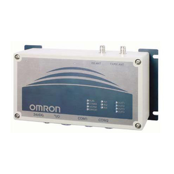
Page 18: Reader/Writer (V720S-Bc5D4A)
Turns on when the input signal is on. OUT1 - OUT4 Green Turns on when the output signal is on. Note ●Do not connect antennas other than those recommended by OMRON. ●When connecting a Receive-only Antenna, enable the Receive-only Antenna Mode with the Antenna Changeover Command (AC). -
Page 19: Names Of Connector Terminals
2-1 Reader/Writer(V720S-BC5D4A) 2-1-2 Names of Connector Terminals Each connector shows pin numbers ,which are viewed from the outside of the Reader/Writer. 1. Power connector Shape of Name Description connector number Connects 0V. + 24 VDC Connects the + side of 24 VDC. -
Page 20: Specifications
Specifications 2-2-1 General Specifications Item Specifications Supply voltage 24VDC ±10% Power consumption 27 W or less Ambient operating -10℃ to 50℃ (with no icing) temperature Ambient operating humidity 35% to 85% RH (with no condensation) Ambient storage temperature -25℃ to 65℃ (with no icing) 20 MΩ... -
Page 21: Reader/Writer Communications Specifications
2-2 Specifications 2-2-3 Reader/Writer Communications Specifications 1. Transmission specifications Item Specifications Central carrier frequency 13.56 MHz ± 7 kHz V720S-BC5D4: 4.0 W or less Antenna output Output impedance: 50Ω Modulation method Degree of modulation 10% to 20% Fast mode: RZ/1 out of 4 Coding method Standard mode: 1 out of 256 Fast mode: 26.5 kbps... -
Page 22: I/O Specifications
2-2 Specifications 2-2-4 I/O Specifications Input specifications (RST, IN1, IN2, and IN3) Output specifications (OUT1, OUT2, OUT3, and OUT4)) Item Specifications Item Specifications 24VDC ± 10% 24VDC ± 10%, 50mA Max. opening and Input voltage (including ripples) closing capacity (including ripples) Input impedance 2.2 kΩ... -
Page 23: Host Communications Specifications
2-2 Specifications 2-2-5 Host Communications Specifications The RS-232C interfaces for COM1 and COM2 have separate communication ports, and thus it is possible for these interfaces to have different communication settings. COM1 can be communicated via RS-232C or RS485 interfaces. RS-232C for COM2 is primarily used for Reader/Writer setup, whereas RS-485 pin at COM2 is used for multi-drop connection to other Reader/Writer devices. -
Page 24: Dimensions
2-2 Specifications 2-2-6 Dimensions... -
Page 25: Cable (Sold Separately)
2-3 Cable (sold separately) 2-3-1 General Specifications Model V720-A 41 V720-A 51 V720-A 62 Item Antenna cable Power cable RS-232C cable Cable type Coaxial cable Number of conductors 2 (shield) Insulation resistance 10 MΩ min. (at 250 5 MΩ min. (at 250 VDC) 10 MΩ... - Page 26 2-3 Cable (sold separately) ■Power cable: V720-A51 Item Model V720-A51 Length (L1) 3000+10-20(mm) Connection label Red(+24VDC) Black(0V) White(GR) Connector (Reader/Writer side) ■Cable for RS-232C: V720-A62(For DOS/V PCs) Item Model V720-A62 3M V720-A62 15M Length (L1) 3000+50-0 (mm) 15000+50-0 (mm) Connect label Connector (Host side) Connector (Reader/Writer) :The D-sub connector is an inch screw thread (M2.54) type.
-
Page 27: Memory Map Of Tag
●This product incorporates the firmware, which can access the 4-byte/page chip that conforms to ISO/IEC 15693. However, the operation is guaranteed for OMRON Tags that use the Philips Semiconductor IC, SL2ICS20 (commonly called I.CODE SLI) only. The Tags by other manufactures, or those with other ISO/IEC15693 Chips should be thoroughly tested by each user. - Page 28 2-4 Memory Map of Tag 2) System area of I.CODE2 chip This section describes a system area of I.CODE SLI chip. The system area of I-CODE SLI chip is allocated in the other area rather than user memory area. Execute a specific command to access to the system area. The processes in the system area are done by specific commands instead of page number allocations.
- Page 29 2-4 Memory Map of Tag (4) DSFID DSFID indicates how data are organized in a memory. Byte3 DSFID (5) Write-access conditions The pages are write-inhibited permanently if they are so indicated in the memory map. The factory settings are as follow. If the bit of a particular page is 1, that page is write-protected.
-
Page 30: I.code1Chip
The memory is organized with four bytes as one page (4 bytes = 32 bits). One page is the minimum unit that can be read from and written to the memory. The memory allocation described in these specifications is in accordance with OMRON's memory allocation scheme. 1)Memory map of I.CODE1Chip OMRON PHILIPS (Page) - Page 31 2-4 Memory Map of Tag 2) System area of I.CODE2 chip 1)SNR (pages FB and FC) SNR is a Tag-specific code and has been written into the memory during the chip production process. The IC is shipped with this page write-access inhibited (refer to page FD);...
-
Page 32: Functions
SECTION 3 Functions Operating Mode....................3-2 3-1-1 Chip Operating Mode..................3-2 3-1-2 Online Mode/Offline Mode ................3-2 Communication Modes..................3-3 3-2-1 Single Access ....................... 3-3 3-2-2 FIFO Access......................3-3 3-2-3 Multiple Access....................3-4 3-2-4 Selective Access ....................3-4 3-2-5 Fast Read Access: I.CODE1 Mode only ............. 3-5 Memory Check Function: I.CODE1 Mode Only .......... -
Page 33: Operating Mode
3-1 Operating Mode 3-1-1 Chip Operating Mode This Reader/Writer has two Chip-Operating Modes for different types of Tags (and its IC Chips.) You have to set either of the Chip Operating Modes in accordance with the Tag you choose. The functions or command types/formats vary, depending on the Chip Operating Mode. -
Page 34: Communication Mode
3-2 Communication Modes This Reader/Writer has five communication modes to be selected by each command corresponding to the number and/or state of Tags in the communication area. Each mode is activated by specifying the communication in the command data. 3-2-1 Single Access Single Access is used to read data from or write data on the only Tag that exists in the Antenna Communication Area. -
Page 35: Multiple Access
3-2 Communication Modes 3-2-3 Multiple Access Multiple Access is used to read data from or write data on the Multiple Tags in the Antenna Communication area simultaneously. Communications with Multiple Tags in the communications area is available. (This function is also called 1:N Access or Multiple Tag Simultaneous Access). -
Page 36: Fast Read Access: I.code1 Mode Only
3-2 Communication Modes 3-2-5 Fast Read Access: I.CODE1 Mode Only The Fast Read Access speeds up the data readout in I.CODE1 Mode. The execution timing can be selected from Trigger, which executes immediately, Auto, which waits for the Tag to enter the communication area and executes, or Repeat, which repeats the execution for the Tag in the communication area. -
Page 37: Memory Check Function I.code1 Mode Only
Memory Check Function I.CODE1 Mode Only By adding a check code to the data in the Tag, you can detect data errors due to the Tag memory (EEPROM) being overwritten, service life, and unforeseen factors. The check code uses the CRC code of the generating polynomial X + 1. -
Page 38: Lock Function
3-4 Lock Function The Lock function protects data from being erased due to unintentional overwriting on the fixed data in the Tags. ■ Lock setting in ISO mode For the lock setting in ISO mode, you can write-protect any given areas by the page of Tag memory. -
Page 39: Discriminating Access To Tag Function
3-5 Discriminating Access to Tag Function The ID codes set in the Tags are utilized in identifying the target chips in the antenna’s application fields. Responses are returned only when the ID code in the command from the antenna and the ID code on the Tag are matched. -
Page 40: External I/O Function
External I/O Function The I/O connector has three external input ports and four external output ports to which such devices as sensors or actuators are connected to build a more efficient system. The external output may be dedicated to the antenna control, depending on the Reader/Writer settings. -
Page 41: Eas Function
3-7 EAS Function The Reader/Writer supports the EAS (Electronic Article Surveillance) system applied for anti-theft and other devices. The Reader/Writer identifies the unique data string returned by the EAS-bit enabled Tags and detects the existence of the Tags in the communication area. Multiple EAS-bit enabled Tags that exist simultaneously can also be detected. -
Page 42: Duplicate Communication Protecting Function
3-8 Duplicate Communication Protecting Function The Duplicate Communication Protecting Function prevents the command that processes multiple Tags serially from performing multiple Read/Write processing for each Tag. This function controls the command so that it performs the processing only once per Tag and returns a single response, even in situations where a Tag is recognized more than once as shown below. -
Page 43: From Start-Up To Operation
SECTION 4 From Start-up to Operation Operation of Reader/Writer ................. 4-2 4-1-1 Offline Mode..................... 4-2 4-1-2 Online Mode ..................... 4-3 Trial Operation ..................... 4-4 Reader/Writer Setting ..................4-5 4-3-1 Host Communications Setting (COM Port Setting) ........4-5 4-3-2 Chip Operating Mode Setting ................. 4-6 4-3-3 Command Processing Procedure Setting ............ -
Page 44: Operation Of Reader/Writer
Operation of Reader/Writer The V720-series RFID system has two operation modes: Offline Mode and Online Mode. The functions and control methods by the host vary, depending on the Operation Mode. One of the two modes must be selected at system setup. 4-1-1 Offline Mode In the Offline Mode, the EAS-enabled Tags (the EAS function mounted on the Tags is not disabled) are always detected (1). -
Page 45: Online Mode
4-1 Operation of Reader/Writer 4-1-2 Online Mode Communication with Tags (2) is performed according to the command (1) from the connected host. The result is returned to the host as a response (3). The I/O can be read or controlled using commands. -
Page 46: Trial Operation
4-2 Trial Operation Check the following points before starting Trial Operation ■Checkpoints No. Checkpoint Description Section-Item Are the power supply Wired properly? SECTION 4-6 1 and I/O lines connected Are the terminal screws properly tightened? Antenna connection Is the Antenna connected properly? 2... -
Page 47: Reader/Writer Setting
Reader/Writer Setting The Reader/Writer has been designed for the user to make all the settings by issuing commands from the host. The user can use either the COM1 or COM2 port to make settings. However, we recommend use of the COM2 port because its communications settings have been fixed at factory to survive a power reset. -
Page 48: Chip Operating Mode Setting
4-3 Reader/Writer Setting 1) Communications type setting for COM1 port Set whether COM1 will be used as RS-232C or RS-485 by using the communications type setting command (CT) Setting name Default set value Setting range (command name) Communications RS-232C type setting *1 RS-232C RS-485 (CT command) -
Page 49: Command Processing Procedure Setting
4-3 Reader/Writer Setting 4-3-3 Command Processing Procedure Setting 1)UID/SNR Addition Setting For the Read command response in I.CODE1 Mode or the Read/Write command response in ISO Mode, whether to add the UID/SNR (a serial number which is a unique ID given to a Tag) must be selected. When enabled, this command makes association of data contained in a Tag to the serial number of that Tag considerably easier. -
Page 50: Antenna And Tag Communications Setting
4-3 Reader/Writer Setting 4-3-4 Antena and Tag Communications Setting Set how communications should take place between the Reader/Writer and a Tag. 1) Reader/Writer-Tag communications speed setting Set the speed of communications between the Reader/Writer and a Tag (baud rate from the Reader/Writer to a Tag). The baud rate from a Tag to the Reader/Writer is fixed (26.5kbps). -
Page 51: Offline Mode Setting
4-3 Reader/Writer Setting 4-3-5 Offline Mode Setting Set whether the Reader/Writer will start in offline mode or online mode. This setting can be made by using the offline mode setting command (FL) Setting name Setting Default set value (command name) range Offline Mode Setting Enabled,... -
Page 52: Installation Environment
Installation Environment The V720S-BC5D4 Reader/Writer is a highly reliable control device withstanding tough environments. In order to ensure the full, reliable performance of the RFID system, however, observe the following. 4-4-1 Installation Do not install the Controller under the following conditions. •... -
Page 53: Mounting Method
Mounting Method The Reader/Writer must be mounted using a mounting plate. When mounting, be sure to secure it onto the mounting plate with M6 screws, spring washers and flat washers. Do not apply organic solvent, e.g., screw lock solvent, to the screws to secure the Reader/Writer. -
Page 54: Wiring Method
Reader/Writer side Connector plug Connected to Pin No. Name 24 VDC + 24 VDC ● Recommended Compact DC Power Supply (OMRON) Model Output capacitance Input voltage S82K-03024 24VDC at 1.3A 100/200V Attach the ferrite core (accessory) for the cable to supply 100VAC. -
Page 55: Host Communications Cabling
4-6 Wiring Method 4-6-2 Host Communications Cabling 4-6-2-1 RS-232C Interface Cabling V720-HS04 V720-HS04 RS-232C cable RS-232C cable V720-A62 V720-A62 Antenna cable Antenna cable V720-A41 V720-A41 COMM COMM COMM NORM NORM NORM ERROR ERROR ERROR Power supply Power supply S82K-03024 S82K-03024 AC100V AC100V Power supply cable... - Page 56 COM1、COM2 Connector of cable COM1, COM2 25-pin, male + − (シールド線) Shield wire 3) Connection to OMRON C200H PLC (Pin layout when cable connector is viewed from engaging face) Reader/Writer リーダライタ Connecting Device 接続機器 形 C200H-ASC02 C200H ASC02 C O M 1 、 CO M 2 COM1, COM2 ケーブルに付いたコネクタ...
-
Page 57: Interface Cabling
5 ms after completion of transmission of commands. If you fail to do this, the host may not be able to communicate with the Reader/Writer. 5 ms 上位機器 Host コマンドフレーム コマンドフレーム Command frame Command frame V720S-BC5D4A レスポンスフレーム 形V720-BC5D1 Response frame 4-15... - Page 58 4-6 Wiring Method 1) Example of wiring for 1-to-1 connection V720S-BC5D4A V720-BC5D1 Host 上位機器 + COM1 COM2 − Terminal resistance Terminal resistance 終端抵抗220 Ω 終端抵抗 2 2 0 Ω 220Ω is on 220Ω is on あり あり Note Be sure to turn on the terminal resistance on both the host and Reader/Writer sides.
- Page 59 4-6 Wiring Method ■ Example of wiring between host and Reader/Writer Host side Reader/Writer side Pin layout when cable connector on Connector plug Reader/Writer is viewed from engagingface Connected to (accessory) Name Pin number 1 2 3 Port COM1 COM2 4...
-
Page 60: Assembly Of Connector
4-6 Wiring Method 4-6-3 Assembly of Connector 4-6-3-1 Assembly of Host Communications Connector and I/O Connector 1) Disassemble the connector as follows: (1) Loosen the set screw and remove the barrel from the end bell (by turning it counterclockwise). (2) Loosen the clamp screw, remove the clamp saddle from the end bell. -
Page 61: Assembly Of Connector
Model name of I/O connector plug: NJC-2010-PM from Nanaboshi Electric Mfg. Co., Ltd. Before use, be sure to check for the proper torques of the cable of your choice. OMRON does not offer any guarantee for customer-made cables. Please inquire to the manufacturer for details of these connectors. -
Page 62: Control From Host
SECTION 5 Control from Host Control by Commands ..................... 5-3 5-1-1 Control by Commands ..................5-3 5-1-2 Command-Response Flow ..................5-3 5-1-3 ACK/NACK Control ....................5-4 Control Procedures for Each Communication Mode ..........5-5 5-2-1 Single Access ......................5-5 5-2-1-1 Single Trigger Mode ...................5-5 5-2-1-2 Single Auto Mode..................5-5 5-2-1-3... - Page 63 5-5-3 System Lock (SL): ISO Mode only..............5-42 5-5-4 Read (RD)-SNR Read: I.CODE1 Mode only............5-43 5-5-5 EAS Setting (ES): I.CODE1 Mode only ............5-44 5-5-6 QuietBit Setting (QB): I.CODE1 Mode only............. 5-44 5-5-7 Lock Setting (LK): ISO Mode................5-45 5-5-8 Lock Setting Read (LR): ISO Mode only ............
-
Page 64: Control By Commands
5-1 Control by Commands 5-1-1 Control by Commands The Reader/Writer operation is controlled by the commands from the connected host. The result of the command execution is returned as a response. In Online Mode, all the operations, such as Tag-data Reading/Writing, Tag-function setting, operating condition setting, or Reader/Writer function control, are controlled by the commands. -
Page 65: Ack/Nack Control
5-1 Control by Commands 5-1-3 ACK/NACK Control When using ACK/NACK control, if the host does not receive a normal response, the Reader/Writer will resend the response by either (1) when the host sends a NACK command to the Reader/Writer or (2) when there is no response within a set period of time. -
Page 66: Control Procedures For Each Communication Mode
5-2 Control Procedures for Each Communication The operating sequences including the communication with the Tag or timing for returning the response vary, depending on the communication mode. The communication mode is set by specifying the communication mode in the command data. The access and mode specified as the communication settings must be those specifiable for each Tag status in the specified antenna’s communication area or the connection topology with the host. -
Page 67: Single Repeat Mode: Iso Mode
5-2 Control Procedures for Each Communication 5-2-1-3 Single Repeat Mode: ISO Mode The Reader/Writer waits for a Tag to enter the R/W Antenna’s communications area. Every time a Tag enters the communications area, the Reader/Writer communicates with the Tag and returns a response. -
Page 68: Polling Auto Read
5-2 Control Procedures for Each Communication 5-2-1-4 Polling Auto Read If an Auto command is used when a single host controls more than one Reader/Writer, the communications path between the host and one of the Reader/Writers to which the command is sent becomes busy, disabling the host to control other Reader/Writers. -
Page 69: Fifo Access
5-2 Control Procedures for Each Communication 5-2-2 FIFO Access In FIFO (first-in, first-out) access, communications with Tags entering the communications area one after another are carried out in sequence. Once communications with Tags are completed, access to them is prohibited. Consequently, even if Tags with which communications are already completed exist in the communications area, a newly entering Tag can be accessed. -
Page 70: Fifo Auto Mode
5-2 Control Procedures for Each Communication 5-2-2-2 FIFO Auto Mode The Reader/Writer waits until the Tag has entered the antenna communication area and executes the command it received from the host. The Reader/Writer prohibits access to the Tag after the communication has been completed, and keeps the antenna oscillated to maintain the FIFO access. -
Page 71: Fifo Repeat Mode
5-2 Control Procedures for Each Communication 5-2-2-3 FIFO Repeat Mode The Reader/Writer waits until the Tag has entered the antenna communication area and starts communicating. It communicates with the Tags serially as they enter the antenna communication area, and returns the responses. When the communication has been completed, the Reader/Writer makes the Tag inaccessible, so that it can communicate with the next Tag that entered the area although the Tags with which the Reader/Writer has completed the communication are still present in the same area. -
Page 72: Multiple Access
5-2 Control Procedures for Each Communication 5-2-3 Multiple Access In Multiple Access, the Reader/Writer can communicate with all of the multiple Tags present in the antenna communication area. In I.CODE1 Mode, the Tag code corresponding to the number of Tags present in the communication area must be specified. For the Tag number specifications, refer to SECTION 5-2-5. - Page 73 5-2 Control Procedures for Each Communication In Write Command (WT) with UID/SNR addition setting disabled (in I.CODE1 Mode, the command with UID/SNR addition setting eabled is also covered), the Reader/Writer communicates with all the Tags in the communication area on receiving the command, and returns the results of the communications with each tag as a response.
-
Page 74: Multiple Repeat Mode
5-2 Control Procedures for Each Communication 5-2-3-2 Multiple Repeat Mode Read Command (RD) Write Command (WT) with UID/SNR addition setting enabled (Excluding I.CODE1 Mode). The Reader/Writer continues to return a response every time it has communicated with a Tag in the communication area. -
Page 75: Selective Access
5-2 Control Procedures for Each Communication 5-2-4 Selective Access Selective Access is a function to communicate with the specified Tags among multiple Tags in the antenna communication area. The processes vary depending on the Reader/Writer’s mode. 5-2-4-1 ISO Mode First, the Reader/Writer reads out the UID of the Tag in the communication area using Read Command (in multiple processing modes). - Page 76 5-2 Control Procedures for Each Communication ■ Selective Access Operation: In ISO Mode (Host) (Reader/Writer) (Tag) (1) The Reader/Write receives a command. Multi-Read Command (UID Additional Setting) Tag (UID1) (2) The Reader/Writer communicates with the Waits for a Tag Tag. A response (UID1) (3) The Reader/Writer returns a response with UID.
-
Page 77: I.code1 Mode
5-2 Control Procedures for Each Communication 5-2-4-2 I.CODE1Moed After allocating the Temporary numbers to the Tags in the communication area using Tag Detection Command, the Reader/Writer communicates with the Tags based on the allocated numbers. The Tag code must be specified as command data according to the numbers of the Tags present in the communication area. -
Page 78: I.code1 Mode
5-2 Control Procedures for Each Communication ■ Selective Access Operation: In I.CODE1 Mode (Host) (Reader/Writer) (Tag) (1) Reader/Writer receives a command Tag Detection Command (RD) Communications process Tag (0) (2) The Reader/Writer communicates with the Tag; it Adds a temporary number to the response and stores it within the Reader/Writer. -
Page 79: Specifying A Tag Code: I.code1 Mode
Command-Response Format 5-2-5 Specifying a Tag Code: I.CODE1 Mode The timeslot setting is the setting in the command frame when communicating with multiple Tags simultaneously using Multi-system commands. This setting must be set according to the number of Tags with which to communicate simultaneously. Refer to the table below for the relationship between the number of Tags and this setting. -
Page 80: Command Frame Structure
Command-Response Format 5-3-1 Command Frame Structure The Reader/Writer continuously receives signals from STX through ETX, and executes the command when the correct node number is received (*1). If, after receiving an STX signal, another STX signal is received before an ETX signal is received, the second STX signal is given command priority. Node No. -
Page 81: Command Code List
Command-Response Format 5-3-3 Command Code List The command type is set by specifying the following command types as a command code: There are four major types of commands. (1) Communications command This command communicates with a Tag. (2) System command This command accesses to the system area of a Tag. - Page 82 Command-Response Format Antenna Sets the antenna changeover in the Reader/Writer. Changeover Terminal Resistance Sets the terminal resistance for RS485 in the Reader/Writer. Sets which mode the Reader/Writer will start online or Offline Mode Setting offline. Initialization of Reset the Reader/Writer to the factory settings. Setting Set Value Writing Stores the Reader/Writer set value on the EEPROM...
- Page 83 Command-Response Format communicates with the entering Tag and returns a response. After sending the response, the Reader/Writer will continue to operate until it receives a FIFO command, Stop command (ST), or Reset command(XZ). After sending the response, the Reader/Writer enters a command waiting state.
- Page 84 Command-Response Format 5-3-5 Command-by-Command Communication Method List The communication modes specifiable as a communications method vary, depending on the command. Communications method options are not provided for some commands, their communication methods are determined by specifying the command types. Communica- Fast Single FIFO...
-
Page 85: Specifying A Data Code
Command-Response Format 5-3-6 Specifying a Data Code In the Command code area of the command data, whether the Reader/Writer reads or writes data as ASCII code (or JIS8 code) or HEX code numeric data is specified. Name Code Description ASCII Code A character of data occupies 1 byte (1 address) on a Tag as an ASCII code or a JIS 8 code. -
Page 86: Iso Mode
Command-Response Format 5-3-7 Response Code List 5-3-7-1 ISO Mode Response Type Name Description Code Normal “00” Normal completion The received command ends normally with no error. completion “72” Multi-processing end Communications end response when a multi-trigger function is used. “74” Polling command ・... -
Page 87: I.code1 Mode
Command-Response Format 5-3-7-2 I.CODE1 Mode Response Type Name Description Code Normal “00” Normal completion The received command ends normally with no error. completion “72” Multi-processing end Communications end response when a multi-trigger function is used. Selective detection completion Communications end response when a selective access/detection function is used. -
Page 88: Example Bcc Calculation
Command-Response Format 5-3-8 Example BCC Calculation BCC is the result of the horizontal parity calculation of the data right after STX up to ETX inclusive. Refer to JIS5001 Transmission Path Character Configuration and Using Horizontal Parity for details. Command Node No. code Text Command... -
Page 89: Communication Commands
Communication Commands 5-4-1 Read (RD) This command reads data from a Tag in the communications area.This is also used to read some system areas in I.CODE1. <Command Format> STX Node No.. Command Communic Data First read No. of ETX BCC Code ations type... -
Page 90: Write (Wt)
Communication Commands 5-4-2 Write (WT) Writes data to the Tag in the communication area. Also used to write data to some system areas in I.CODE1. There is no need to perform the verify read process, since this command performs it as part of its execution. - Page 91 Communication Commands <Response Format> (1)In ISO mode 1) The completion of write (In a case where UID (SNR) additional setting is invalid) Command STX Node No. Retry Response No. of ETX BCC code flag code written “WT” “00” pages As specified 2)The completion of write (In a case where UID (SNR) additional setting is valid) There are responses according to the number of Tags in communications area when multi- communications method is preferred.
-
Page 92: Read (Rd)-Tag Detection: I.code1 Mode Only
Communication Commands 5-4-3 Read (RD)-Tag Detection: I.CODE1 Mode only This command assigns temporary Tag numbers to each of multiple Tags that are present in the communications area. This command is available only when the system is in I.CODE1 mode. In ISO mode, you must enable UID (SNR) additional setting, execute 5-3-1 Read Command (RD), and get UID since the system uses UID (SNR) data as a temporary number. -
Page 93: Read (Rd)-Uid Select/Specified Tag
Communication Commands 5-4-4 Read (RD)-UID Select/Specified Tag In ISO mode, this command reads data from the Tag in communications area by specifying UID (SNR). In I.CODE1 mode, this command reads data from the Tag which is specified by the Temporary Number. -
Page 94: Write (Wt)-Uid Select/Specified Tag
Communication Commands 5-4-5 Write (WT)-UID Select/Specified Tag This command writes data to the Tag of either UID (SNR) (in ISO mode) or Temporary Number (in I.CODE1 mode). <Command Format> Node Command code Communi Data First First UID(SNR) Write ETX BCC No.. -
Page 95: Read (Rd)-Fast Read Access: I.code1 Mode Only
Communication Commands 5-4-6 Read (RD)-Fast Read Access: I.CODE1 Mode only When there is only a single Tag in the communications area, this command enables to read data from the Tag faster than a usual Read. <Command Format> Command STX Node No.. Communi Data Setting... -
Page 96: Polling Single Auto Read (Pr)
Communication Commands 5-4-7 Polling Single Auto Read (PR) Immediately after receiving the Polling Single Auto Read Command, the Reader/Writer returns a response indicating the acceptance of the command, and waits for a Tag to enter the communications area of the Antenna. Then it reads the data of the entering Tag. The host can inquire of the Reader/Writer about the results of communications processing using the Polling Check (PC) command. -
Page 97: Polling Single Auto Write (Pw)
Communication Commands 5-4-8 Polling Single Auto Write (PW) Immediately after receiving the Polling Single Auto Write Command, the Reader/Writer returns a response indicating the acceptance of the command and waits for a Tag to enter the communications area of the Antenna. Then it writes data to the entering Tag. The host can inquire of the Reader/Writer about the results of communications processing using the Polling Check (PC) command. -
Page 98: Polling Check (Pc)
Communication Commands 5-4-9 Polling Check (PC) You can check the results while the Polling Single Auto Read Command and Polling Single Auto Write Command are being executed. You can use Polling Check after the Polling Single Auto Read Command and Polling Single Auto Write Command have been sent. <Command Format>... -
Page 99: Polling End (Pe)
Communication Commands 5-4-10 Polling End (PE) This command aborts the execution of Polling commands. It is used after a Polling command is sent. <Command Format> Command STX Node No.. ETX BCC code “PE” <Response Format> (1) Before the completion of communications with a Tag Command STX Node No.. -
Page 100: Memory Check (Mc): I.code1 Mode Only
Communication Commands 5-4-11 Memory Check (MC): I.CODE1 Mode only This command uses the generating polynomial, X + 1 to calculate the range of the check block designated by a user and to compare the results with the check code attached to the check block. <Command Format>... -
Page 101: System Command
System Command 5-5-1 System Read (SR): ISO Mode only This command read system information in the system area of the Tag. <Command Format> STX Node No.. Command System code type method“00 “SR” ” Tag type Specified a Tag type A: I.CODE SLI chip System method Specified the kind of system information. -
Page 102: System Write (Sw): Iso Mode Only
System Command 5-5-2 System Write (SW): ISO Mode only This command writes the settings of AFI, DSFID, and EAS to a Tag. <Command Format> (1) For normal write Node No.. Command code System data ETX BCC “SW” type method (2) When UID of a Tag is specified STX Node No.. -
Page 103: System Lock (Sl): Iso Mode Only
System Command 5-5-3 System Lock (SL): ISO Mode only This command locks (write-inhibit) to write to system area information of a Tag. <Command Format> (1) Normal lock Node No.. Command code System ETX BCC “SL” type method (2) In a case where UID of a Tag is specified Node No.. -
Page 104: Read (Rd)-Snr Read: I.code1 Mode Only
System Command 5-5-4 Read (RD)-SNR Read: I.CODE1 Mode only This command read SNR (Tag-specified code) which incorporates I.CODE1 chip. Refer to 2-4 of Section 2 Memory Map of Tag. <Command Format> Node No.. Command code Communications Data Fixed Fixed ETX BC “RD”... -
Page 105: Eas Setting (Es): I.code1 Mode Only
System Command 5-5-5 EAS Setting (ES): I.CODE1 Mode only This command sets the EASBit of a Tag incorporating I.CODE1 chip. When the EASBit is disabled, the Reader/Writer will not return a response to the EAS Check Command (EA). <Command Format> Node No.. -
Page 106: Lock Setting (Lk): Iso Mode
System Command 5-5-7 Lock Setting (LK): ISO Mode This command is used to set and check the write-protection of Tags incorporating I.CODE1 chip. A Tag can be locked (or write-protected) by memory page. <Command Format> Node No.. Command code First lock page lock ETX BCC “LK”... -
Page 107: Lock Setting Read (Lr): Iso Mode Only
System Command 5-5-8 Lock Setting Read (LR): ISO Mode only This command reads lock setting information of a Tag incorporating I.CODE SLI chip. <Command Format> Node No.. Command code First lock page No. of lock ETX BCC “LR” type pages Tag type Specifies Tag type. -
Page 108: Lock Setting (Lk): I.code1 Mode
System Command 5-5-9 Lock Setting (LK): I.CODE1 Mode This command is used to set and check the lock (write-protection) of Tags incorporating I.CODE1 chip. A Tag can be locked (or write-protected) by memory page. To read lock information set in a Tag, set all lock information in the commands to 0. <Command Format>... -
Page 109: Eas Check (Ea)
System Command 5-5-10 EAS Check (EA) This command transmits the EAS command continuously and returns the percentage of data that matches the EAS response code. <Command Format> 1)In ISO mode Node No.. Command code ETX BCC “EA” type 2)In I.CODE1 mode Node No.. -
Page 110: Reader/Writer Control Commands
Reader/Writer Control Commands 5-6-1 Stop (ST) Stop (ST) Stop command terminates Auto mode, Repeat mode, EAS check and other command processings, as well as continued FIFO state after FIFO Access, or Select state after executing Detection command, returning to the Reader/Writer to a stand-by status to wait for commands. <Command Format>... -
Page 111: I/O Control Command (Cc)
Reader/Writer Control Commands 5-6-5 I/O Control Command (CC) This command changes the state of the user output terminals (OUT1 to OUT4) and reads the state of the user input terminals (IN1 to IN3). <Command Format> Node No. Command ETX BCC code "CC"... -
Page 112: Version (Vs)
Reader/Writer Control Commands 5-6-7 Version (VS) This command reads the software version for the Reader/Writer. <Command Format> Node No. Command ETX BCC code "VS" <Response Format> Node No. Retry Command Response Software version ETX BCC flag code code "VS" "00" Response code 00: Normal completion For other Response Codes, refer to SECTION 5-3-7 Response Code List. -
Page 113: Setting Command
Setting Command 5-7-1 Reader/Writer AFI Enable/Disable Changeover (AE): ISO Mode only In ISO mode, you must set AFI of the Reader/Writer either enable or disable when communicating with a Tag. If you set AFI enable, only Tags, which has the same AFI, can be communicated. When you set AFI disable, the communications are enabled no matter AFI in Reader/Writer is set or not. -
Page 114: Reader/Writer Family Code Setting (Fc): I.code1 Mode
Setting Command 5-7-3 Reader/Writer Family Code Setting (FC): I.CODE1 Mode The FC Command is used to set or read the Family Code in the Reader/Writer. Only Tags that have the same Family Code as the one set by this command can perform communications. If this Family Code is set to 00, communications will be possible with all Tags. -
Page 115: Uid/Snr Addition Setting (Sn)
Setting Command 5-7-5 UID/ SNR Addition Setting (SN) This command selects whether SNR will be added to a response to a Read Command (excluding Special Read). <Command Format> Node No. Command Additi ETX BCC code "SN" mode Specify whether SNR will be added to a response. Addition mode Setting range: 0 to 1, or * When * is specified, the Reader/Writer reads the number that is... -
Page 116: Node Number Setting(Nn)
Setting Command 5-7-6 Node Number Setting(NN) This command sets and reads the node number of the Reader/Writer. <Command Format> Node No. Command Node number ETX BCC code change "NN" specification Node number Specifies the node number in decimal that you want to change. change Specification range: 00 to 31, ** specification... -
Page 117: Communications Port Setting(Cp)
Setting Command 5-7-7 Communications Port Setting(CP) This command sets the baud rate for the communications port (Com Port), data length, parity bit, and stop bit for use in communications with the host. <Command Format> Node No. Command Port Baud Data Parit Stop time... - Page 118 Setting Command <Response Format> Node No. Retry Command Response Port Baud Data Parity Stop Time ETX BCC flag code code: rate length Enabled NACK "CP" "00" /Disabled Response code: 00: Normal completion For other Response Codes, refer to Response Code List. Port No.
-
Page 119: Communications Type Setting (Ct)
Setting Command 5-7-8 Communications Type Setting (CT) This command selects whether COM1 will be used as RS-232C or RS-485. <Command Format> STX Node No. Command Commni ETX BCC code cations "CT" type Communications Specify the number corresponding to the communications type that type you want to select. -
Page 120: Antenna Changeover(Ac)
Setting Command 5-7-10 Antenna Changeover(AC) This command selects whether the receiving function of each antenna will be enabled or disabled. <Command Format> Node No. Command Antenna ETX BCC code selection "AC" Antenna Specify the number corresponding to how TX/RX ANT and RX ANT selection will be used. -
Page 121: Offline Mode Setting (Fl)
Setting Command 5-7-12 Offline Mode Setting (FL) This command selects whether the Reader/Writer will start in online mode or offline mode. When offline mode is selected, the Reader/Writer will perform EAS check independent of the host, and output a signal from the output port (OUT1) if the result exceeds the specified criterion. -
Page 122: Set Value Initialization (Is)
Setting Command 5-7-13 Set Value Initialization (IS) If necessary, you can return all the settings to their factory settings. <Command Format> Node No. Command ETX BCC code "IS" <Response Format> Node No. Retry Command Response ETX BCC flag code code: "IS"... -
Page 123: Chip Operating Mode Switch (Ty)
Setting Command 5-7-15 Chip Operating Mode Switch (TY) This command changes the operating mode (ISO/I.CODE1) of the Reader/Writer. <Command Format> STX Node No.. Command code ETX BCC “TY” type Tag type Specifies the mode. 0: I.CODE1 mode 1: ISO mode When the Operating Mode is set to "**,"... -
Page 124: Duplicate Communication Protecting Function Setting (Mx) [Ver1.20 And Higher]
Setting Command 5-7-16 Duplicate Communication Protecting Function setting (MX) This command specifies the enabled/disabled state of the duplicate communication protecting function and the number of tables in the enabled state. When the function is enabled, the Tag is read only once at the execution of a command with FIFO Repeat (FR), Multiple Trigger, or Multiple Repeat (MR, UR [I.CODE1 mode]) options. -
Page 125: I/O Automatic Changeover Setting (Ca) [Ver1.20 And Higher]
Setting Command 5-7-17 I/O Automatic Changeover setting (CA) This function alternately turns the output terminals (OUT3 and OUT4) ON and OFF for Multiple Repeat and EAS. Check commands every time the command is issued. This is used to switch multiple antennas automatically. Enable the function when a special antenna that requires this function is used. -
Page 126: Other Commands
Other commands 5-8-1 Command Undefined Response When the Reader/Writer receives a command code which is not on the command list, the Reader/Writer returns the Command Undefined Response. <Response Format> Node No.. Retry Command ETX BCC flag code“IC” 5-65... -
Page 127: Command Connection: I.code1 Mode Only
5-9 Command Connection: I.CODE1 Mode only This Command Connection works in I.CODE1 Mode Only, and does not support ISO Mode. A command connection function allows the Reader/Writer to perform a pair of read and write operations at a time by sending a command only once. Any of the following six commands can be paired. - Page 128 5-9 Command Connection: I.CODE1 Mode only The Following Combinations of Command Connections Are Possible. Command (1) Memory Memory Polling Polling Read Write Calculati check read write (RD) (WT) (MC) (PR) (PW) (MK) Read(RD) − − − − Write(WT) − − −...
-
Page 129: Startup And Full Operation
SECTION 6 Startup and Full Operation Error Types and Diagnostic Functions .............. 6-2 Errors and Remedies ..................6-3 Maintenance and Inspection ................6-4 Troubleshooting ....................6-6 6-4-1 Check Flowchart ....................6-6 6-4-2 Check Items for Each Response Code ……………………………………… ……6-10... -
Page 130: Error Types And Diagnostic Functions
6-1 Error Types and Diagnostic Functions The Reader/Writer performs a variety of self-diagnostic functions to reduce system downtime in case of an error. The errors detected by the Reader/Writer are categorized into fatal errors and nonfatal errors. Fatal Error If the Reader/Writer main unit or hardware fails, the CPU operation is interrupted and the ERROR LED is turned on or flashed. -
Page 131: Errors And Remedies
6-2 Errors and Remedies The following are considered to be main causes of system breakdowns. • Noise Interference........Take appropriate countermeasures against noise. • Failures in any of the external devices • Failures in the Reader/Writer • Failures in the Antenna Repairs are required. -
Page 132: Maintenance And Inspection
6-3 Maintenance and Inspection The V720 Series must be inspected on a daily or regular basis so that the functions of the V720 Series can be used in good condition. The V720 Series consists of semiconductors that last almost indefinitely. The following malfunctions may, however, result due to the operating environment and conditions. -
Page 133: Troubleshooting
6-4 Troubleshooting 6-4-1 Check Flowchart Use the following main check flowchart to determine the cause of the error. ■Main Check Flowchart メインチェックフロー Main Check Flowchart Go to System リーダライタは Is the system connection Check コマンド待ち状態 「システム接続チェックフロー」へ connection normal? Flowchart ですか? Go to Host 上位通信は... - Page 134 6-4 Troubleshooting ■System connections check flowchart Start Are the connectors and cables connected properly? Connect the connector/cable properly. Is the specified voltage applied or current supplied? Apply the specified voltage or supply the specified current. Is Reset input ON? Turn OFF Reset Is the RUN LED lit? The Reader/Writer may have failed.
- Page 135 6-4 Troubleshooting ■Host communications Check Flowchart Start Issue TS Command from the host. The lit NORML LED or ERR LED is turned off. Are the communication conditions, command frame, node ID OK? The response has Specify the correct been received. communication settings and node ID.
- Page 136 6-4 Troubleshooting ■Communications Check Flowchart Start Issue Write Command in Single Trigger mode. The lit NORML LED or ERR LED is turned off. The response has been received. Is the response normal? Response Code 7C Refer to section 6-4-2 Check The Reader/Writer Items for Each Response Code.
- Page 137 6-4 Troubleshooting ■External Environment Check Flowchart Start Refer to section 6-3 Are the operating Maintenance and Inspection. conditions working well? Refer to section 6-2 Errors Is the ambient and Remedies. noise OK?
-
Page 138: Check Items For Each Response Code
6-4 Troubleshooting 6-4-2 Check Items for Each Response Code Response Code Primary check items (Nonresponding ・Are the communication conditions set for the host and the Reader/Writer matched? state) Transmission rate, data length, stop bit length, parity (even, odd, none) ・Is the control code (STX/ETX) transmitted properly? ・Are the command node No. -
Page 139: Reference Data
SECTION 7 Reference Data Turn Around Time and Communication Time............7-2 7-1-1 Communication time in I.CODE1 mode..............7-2 7-1-2 ISO mode - Communication time of I.CODE SLI chip ..........7-4 7-1-3 Turn Around Time (TAT) Calculation Method ............7-6 Calculating the speed of the Tag................7-7... - Page 140 7-1 Turn Around Time and Communication Time In the V720-series Reader/Writer, actual communications with a Tag are performed by reading or writing four-byte data per page. • The following chart specifies the TAT (turn-around time) and actual communications time. • The actual communications time in the following chart is the time required for communications between the Antenna and Tag, not including communications with the host.
-
Page 141: Turn Around Time And Communication Time
7-1 Turn Around Time and Communication Time : ・ The provided TAT graph data shows an example in which the V720S-BC5D4A Controller is used with the following communications specifications for host communications: Data is continuously sent with no space between characters, at a baud rate of 38,400 bps, in a data length of 7 bits with 1 start bit, 2 stop bits and even parity . -
Page 142: Iso Mode - Communication Time Of I.code Sli Chip
7-1 Turn Around Time and Communication Time 7-1-2 ISO mode - Communication time of I.CODE SLI chip (1)Communication time in Single Access Mode ● Fast mode Actual 交信時間 communica (ms) (ms) tions time (ms) writing ライト ライト writing リード Reading リード... -
Page 143: Turn Around Time (Tat) Calculation Method
7-1 Turn Around Time and Communication Time The communication time when the commands with multiple access options (2)Communication time in are used varies depending on operating conditions. Those conditions Multiple modes: include the number of bytes, as well as the number of Tags in the communication area. -
Page 144: Calculating The Speed Of The Tag
7-2 Calculating the speed of the Tag When communicating with a Tag in motion, select Auto or Repeat for the communications method. The maximum speed at which the Tag can travel can be obtained easily, using the formula below. D (travel distance in communications area) Max. -
Page 145: Appendix
SECTION 8 Appendix Appendix 1 Accessories ....................8-2 Appendix 2 JIS8 Code Table (ASCII Code Table) ............8-3... -
Page 146: Appendix 1 Accessories
Tokyo 164-0022 TEL: 03-3386-3181 FAX: 03-3388-1561 3) Ferrite core Clamp the ferrite core around the wire near the 100VAC of power supply (S82K-03024 from OMRON recommended). For attachment method, refer to 4-6-1 “Power Supply and Grounding Wires”. <Contact> TDK. Corporation... -
Page 147: Appendix 2 Jis8 Code Table (Ascii Code Table)
Appendix 2 JIS8 Code Table (ASCII Code Table) High Order b8 - b5 0000 0001 0010 0011 0100 0101 0110 0111 Low Order b4 - b1 Colum 0000 (DLE) (SP) 0001 (SOH) 0010 (STX) " 0011 (ETX) 0100 (EOT) 0101 (NEQ (NAK 0110... - Page 148 Revision History A manual revision code appears as a suffix to the catalog number on the front cover of the manual. SRFM- 002A Revision code The following table outlines the changes made to the manual during each revision. Page numbers refer to the previous version.
- Page 149 Rm.302, AZIA Center, 1233 Lujiazui Ring Road Pudong New Area, Shanghai 200120, PRC. Tel: (86)21-5888-1666 Fax: (86)21-58888-7633/7933 Up-to-date information on RFID Systems can be accessed at OMRON's web site at http://www.omronrfid.com/ Authorized Distributor: Manual No. SRFM-005A Note: Specifications subject to change without notice.
Need help?
Do you have a question about the V720S-BC5D4A and is the answer not in the manual?
Questions and answers