Omron V680-HS63 User Manual
V680 series, fl remote id, antenna, rf tag
Hide thumbs
Also See for V680-HS63:
- User manual (238 pages) ,
- User manual (44 pages) ,
- User manual (143 pages)
Table of Contents
Advertisement
RFID System
V680 Series
User's Manual
V680-HAM42-FRT
V680-D1KP52MT
V680-D1KP53M
V680-D1KP66T/D1KP66MT
V680-D1KP66T-SP
V680-D2KF52M
V680-D8KF67/-D8KF67M
V680-D8KF68/-D32KF68
V680S-D2KF67/-D2KF67M
V680S-D2KF68/-D2KF68M
V680S-D8KF67/-D8KF67M
V680S-D8KF68/-D8KF68M
FL Remote ID
Antenna
V680-HS51
V680-HS52
V680-HS63
V680-HS63-SP
V680-HS65
RF Tag
Man. No. Z268-E1-06
Advertisement
Table of Contents

Related Manuals for Omron V680-HS63


Summary of Contents for Omron V680-HS63
- Page 1 RFID System V680 Series User’s Manual FL Remote ID V680-HAM42-FRT Antenna V680-HS51 V680-HS52 V680-HS63 V680-HS63-SP V680-HS65 RF Tag V680-D1KP52MT V680-D1KP53M V680-D1KP66T/D1KP66MT V680-D1KP66T-SP V680-D2KF52M V680-D8KF67/-D8KF67M V680-D8KF68/-D32KF68 V680S-D2KF67/-D2KF67M V680S-D2KF68/-D2KF68M V680S-D8KF67/-D8KF67M V680S-D8KF68/-D8KF68M Man. No. Z268-E1-06...
- Page 2 Introduction Thank you for purchasing a V680/V680S-series RFID System. This manual describes the functions, performance, and application methods needed for optimum use of the V680/V680S-series RFID System. Please observe the following items when using the RFID System. Allow the RFID System to be installed and operated only by qualified specialist with a sufficient knowledge of electrical systems.
-
Page 3: Introduction
SECTION 4 Communications SECTION 5 Troubleshooting SECTION 6 Appendices SECTION 7 RFID System V680-HAM42-FRT FL Remote ID V680-HS51 Antenna V680-HS52 Antenna V680-HS63 Antenna V680-HS63-SP Antenna V680-HS65 Antenna V680-D1KP52MT RF Tag V680-D1KP53M RF Tag V680-D1KP66T/-D1KP66MT RF Tag V680-D1KP66T-SP RF Tag V680-D2KF52M... -
Page 4: Read And Understand This Document
Please read and understand this document before using the products. Please consult your OMRON representative if you have any questions or comments. WARRANTY OMRON’s exclusive warranty is that the products are free from defects in materials and workmanship for a period of one year (or other period if specified) from date of sale by OMRON. -
Page 5: Safety Precautions
Introduction Safety Precautions ● Alert Symbols for Safe Use The following symbols are used in this manual to indicate precautions that must be observed to ensure safe use of the V680-HAM42-FRT/V680 Series Antennas/V680 Series RF Tags. The precautions provided here contain important safety information. -
Page 6: Precautions For Safe Use
9. Turn OFF the FL Remote ID power before attaching or removing the Read/Write Antenna. 10. If an error is detected in any Product, immediately stop operation and turn OFF the power supply. Consult with an OMRON representative. 11. Dispose of the Products as industrial waste. -
Page 7: Precautions For Correct Use
Introduction Precautions for Correct Use Always observe the following precautions to prevent operation failures, malfunctions, and adverse effects on performance and equipment. 1. Installation Environment Do not use the Products in the following locations. • Locations exposed to corrosive gases, dust, metallic powder, or salts •... - Page 8 Introduction 3. Storage Do not store the Products in the following locations. • Locations exposed to corrosive gases, dust, metallic powder, or salts • Locations not within the specified storage temperature range • Locations subject to rapid changes in temperature or condensation •...
-
Page 9: Meanings Of Symbols
Introduction Meanings of Symbols Indicates particularly important points related to a function, including precautions and application advice. Indicates page numbers containing relevant information. Indicates reference to helpful information and explanations for difficult terminology. RFID System User's Manual... - Page 10 Introduction MEMO RFID System User's Manual...
-
Page 11: Table Of Contents
Introduction TABLE OF CONTENTS Introduction READ AND UNDERSTAND THIS DOCUMENT Safety Precautions Precautions for Safe Use Precautions for Correct Use Meanings of Symbols TABLE OF CONTENTS SECTION 1 Product Overview Features Part Names and Functions Antennas RF Tags System Configuration 1 System Configuration 2 Application Flowchart SECTION 2 Installation, Connections, and Wiring... - Page 12 Introduction SECTION 5 Communications I/O Specifications Detailed Command Settings Timing Charts SECTION 6 Troubleshooting Handling Errors Errors and Countermeasures Maintenance and Inspection SECTION 7 Appendices Specifications and Dimensions Characteristics According to Operating Conditions Reference Data RF Tag Memory Map RF Tag Memory Capacities and Memory Types Degree of Protection Revision History RFID System...
-
Page 13: Section 1 Product Overview
SECTION 1 Product Overview Features Part Names and Functions Antennas RF Tags System Configuration 1 System Configuration 2 Application Flowchart RFID System User's Manual... -
Page 14: Features
SECTION 1 Product Overview Features The V680-series RFID System uses electromagnetic induction and supports the ISO/IEC18000-3 (ISO/ IEC15693) RFID system international standards. ■ Highly Reliable RF Tag Communications The V680 features highly reliable RF Tag communications developed through the V600-series RFID Systems, making it easy to use on-site. -
Page 15: Part Names And Functions
Node Address Switches (01 to 64) ■ FL Remote Connector Connects to FL Remote Master Unit ■ Power Supply Terminals Connect to 24-VDC power. Recommended Power Supply: S8VS-03024 (OMRON) ■ Antenna Connector Connects to V680 Series Antenna RFID System User's Manual... - Page 16 SECTION 1 Product Overview ■ Operation Indicators DEV (Device Status) The DEV indicator displays the Unit status. Status Definition Normal Lit green Fatal error Lit red Non-fatal error Flashing red No power Not lit RMT (Remote Status) The RMT indicator displays the FL Remote network status. Status Definition Adding link/Participating in remote communications...
- Page 17 The power supply terminals supply 24-VDC power using the included connector. Included connector model: FKC2.5/3-ST-5.08-RF (Phoenix Contact) Pin No. Name Description Functional ground (Ground to 100 or less.) Use the recommended OMRON Power Supply, the S8VS-03024. RFID System User's Manual...
- Page 18 The node address switches set the FL Remote Node Address. This node address is used as the right- most part of the IP address (e.g., xx of 192.168.250.xx). NORM/ERR NODE No. MODE SOURCE : 24VDC 0.3A RFID OMRON Corporation MADE IN JAP NODE No. Item Description Setting method Two-digit decimal number The left rotary switch sets the 10s digit, and the right rotary switch set the 1s digit.
- Page 19 SECTION 1 Product Overview ■ Mode Switch The mode switch sets the FL Remote ID operation mode. NORM/ERR NODE No. MODE OURCE : 24VDC 0.3A RFID MRON Corporation MADE IN JAPAN MODE Item Description Trigger The input signal triggers communications and outputs the result. Auto mode Communications are repeatedly executed and the results are output.
-
Page 20: Antennas
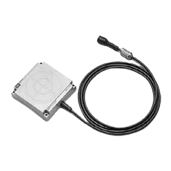
(3) Ferrite core V680-HS52 (4) Connector (2) Communications (1) Operation indicator (3) Ferrite core sufrace (4) Connector V680-HS63 (2) Communications surface (3) Ferrite core (4) Connector (1) Operation indicator V680-HS65 (2) Communications surface (1) Operation (3) Ferrite core... -
Page 21: Rf Tags
SECTION 1 Product Overview RF Tags V680-D1KP52MT/-D2KF52M V680-D1KP53M ■ V680-D1KP66T/-D1KP66MT ■ V680-D1KP66T-SP ■ V680-D8KF67/-D8KF67M ■ V680-D8KF68/-D32KF68 The FL Remote ID communications with the RF Tags through the Antenna to read and write data in the internal memory of the RF Tags. The printed side is the communications surface. - Page 22 SECTION 1 Product Overview ■ V680S-D2KF67/-D2KF67M ■ V680S-D2KF68/-D2KF68M ■ V680S-D8KF67/-D8KF67M ■ V680S-D8KF68/-D8KF68M The FL Remote ID communications with the RF Tags through the Antenna to read and write data in the internal memory of the RF Tags. The printed side is the communications surface. Mount the RF Tags with the communications surfaces facing the Antenna.
-
Page 23: System Configuration 1
NODE No. MODE SOURCE : 24VDC 0.3A RFID SOURCE : 24VDC 0.3A RFID SOURCE : 24VDC 0.3A RFID OMRON Corporation MADE IN JAPAN OMRON Corporation MADE IN JAPAN OMRON Corporation MADE IN JAPAN V680 Series Antennas V680 Series RF Tags ■... - Page 24 SECTION 1 Product Overview System Configuration 2 FL Remote ID V680-HAM42-FRT Connector Antennas V680-HS63 V680-HS63-SP V680-HS65 V680-HS52 V680-HS51 Wireless communications RF Tags V680-D1KP66T-SP V680-D1KP66T/ V680-D1KP52MT V680-D1KP53M -D1KP66MT V680-D8KF67/ V680-D8KF68/ V680S-D2KF67/ V680-D2KF52M V680S-D2KF68/ -D32KF68 -D8KF67M -D2KF67M/ -D2KF68M/ -D8KF67/ -D8KF68/ -D8KF67M -D8KF68M...
-
Page 25: Application Flowchart
SECTION 1 Product Overview Application Flowchart Install the system. p.26 Connect the system. p.28 Set the FL Remote ID communications conditions. p.42 Perform actual communications using commands. p.63 RFID System User's Manual... - Page 26 SECTION 1 Product Overview MEMO RFID System User's Manual...
-
Page 27: Section 2 Installation, Connections, And Wiring
SECTION 2 Installation, Connections, and Wiring FL Remote ID Installing Antennas Installing RF Tags RFID System User's Manual... -
Page 28: Fl Remote Id
■ Installation Method DIN Track V680-HAM42-FRT OMRON NORM/ERR NODE No. MODE SOURCE : 24VDC 0.3A RFID OMRON Corporation MADE IN JAPAN End Plate End Plate Mounting Hook DIN Track End Plate OMRON PFP-100N PFP-100N PFP-M (track length: 1 m) is recommended. - Page 29 OMRON Corporation MADE IN JAPAN OMRON Corporation MADE IN JAPAN OMRON Corporation MADE IN JAPAN End Plate End Plate Spacer Spacer Use at least 2 OMRON DIN Track Spacers. (Each Spacer is 5 mm wide.) Spacer PFP-S RFID System User's Manual...
- Page 30 SECTION 2 Installation, Connections, and Wiring Connection and Wiring ■ FL Remote Connector Installation Hold the connector part of the cable and insert it into the FL Remote Port. Removal Unlock the connector and pull it out. ■ Antenna Connector ...
- Page 31 SECTION 2 Installation, Connections, and Wiring Removing the Antenna Turn the connector in counterclockwise to release the lock. Pull the connector straight out of the port. The connector cannot be removed without turning it to release the lock. If the cable is pulled without releasing the lock, it may cause the cable or Antenna connector wires to break.
- Page 32 If the connector is difficult to remove, press on the FL Remote ID Unit while pulling on the connector. Do not connect cables to the connector after attaching the connector to the FL Remote ID Unit. Use the recommended Power Supply (S8VS-03024, OMRON). RFID System...
-
Page 33: Installing Antennas
SECTION 2 Installation, Connections, and Wiring Installing Antennas V680-HS51 Install the Antenna using the nuts and toothed washer that are provided on both sides of the mounting material, as shown in the diagram below. Metallic material Mounting Hole Dimensions Nuts Antenna +0.5 dia. - Page 34 SECTION 2 Installation, Connections, and Wiring V680-HS63 Installation from the Front Coil center Two, M4 ±0.2 Installation from the Back Insert the nuts that come with the Antenna into sections A. Two, 4.5 dia. Coil center ±0.2 Securely tighten screws to a torque of 1.2 N·m.
- Page 35 SECTION 2 Installation, Connections, and Wiring V680-HS63-SP Installation from the Front Secure the Unit with M4 screws and washers. Coil center Two, M4 holes ±0.2 Installation from the Back Installation from the Back Secure the Unit with M4 screws and washers.
- Page 36 SECTION 2 Installation, Connections, and Wiring V680-HS65 Use M4 screws and spring washers (in four places) for Antenna installation. Four, M4 ±0.2 ±0.2 Securely tighten screws to a torque of 0.7 to 1.2 N·m. Mounting Bracket Dimensions (Provided Only with the V680-HS65) Note: When installing the Antenna, mount it on the enclosed Mounting Bracket.
-
Page 37: Installing Rf Tags
When embedding the V680-D1KP52MT into a metal surface, use the V680-HS51/-HS52 Antenna. Communications will not be possible if the V680-HS63 Antenna is used. Refer to Differences in Surrounding Metals(Reference) in Section 7 Appendices for information on the effect of metal behind the V680-D1KP52MT. - Page 38 SECTION 2 Installation, Connections, and Wiring V680-D1KP66T Mounting Hole Dimensions Mounting on Non-metallic Material Two, M3 M3 pan-head screw Mount the RF Tag using M3 pan-head screws from the marked side. ±0.2 Tightening torque: 0.3 to 0.5 N·m Marked side ±0.2 ...
- Page 39 When embedding the V680-D2KF52M into a metal surface, use the V680-HS51/-HS52 Antenna. Communications will not be possible if the V680-HS63 Antenna is used. Refer to Differences in Surrounding Metals in Section 7 Appendices for information on the effect of metal behind the V680-D2KF52M.
- Page 40 SECTION 2 Installation, Connections, and Wiring V680-D8KF67/-D8KF67M RF Tag Installation Secure the RF Tag with M3 screws. Tighten the Mounting Hole Dimensions screws to a torque of 0.6 N·m. Two, M3 M3 screw ±0.2 Marked ±0.2 side Refer to Effect of Surrounding Metals (Reference) in Section 7 Appendices for information on the effect of metal behind the V680-D8KF67M.
- Page 41 SECTION 2 Installation, Connections, and Wiring V680S-D2KF67/-D2KF67M RF Tag Installation Secure the RF Tag with M3 screws. Tighten the Mounting Hole Dimensions screws to a torque of 0.6 N·m. Two, M3 M3 screw ±0.2 Marked ±0.2 side Refer to Effect of Surrounding Metals (Reference) in Section 7 Appendices for information on the effect of metal behind the V680S-D2KF67M.
- Page 42 SECTION 2 Installation, Connections, and Wiring V680S-D8KF67/-D8KF67M RF Tag Installation Secure the RF Tag with M3 screws. Tighten the Mounting Hole Dimensions screws to a torque of 0.6 N·m. Two, M3 M3 screw ±0.2 Marked ±0.2 side Refer to Effect of Surrounding Metals (Reference) in Section 7 Appendices for information on the effect of metal behind the V680S-D8KF67M.
-
Page 43: Section 3 Preparations For Communications
SECTION 3 Preparations for Communications Parameter Settings for FL Remote Communications RFID System User's Manual... -
Page 44: Parameter Settings For Fl Remote Communications
SECTION 3 Preparations for Communications Parameter Settings for FL Remote Communications Set the following link parameters of the JTEKT PLC to enable using the FL Remote ID. Refer to the JTEKT Master Operation Manual for details on how to set the Link No., Slot No., and Link Module Name. Use JTEKT PCwin Ver 8.** Programming Tool to set the parameters of the FL Remote ID. - Page 45 SECTION 3 Preparations for Communications ■ FL Remote M Detail Settings Click the Details Button in the Link Parameter Settings Dialog Box and select the parameter that you want to use. The FL Remote ID does not have a diagnostic function. Parameters cannot be set for this function. ■...
- Page 46 SECTION 3 Preparations for Communications MEMO RFID System User's Manual...
-
Page 47: Section 4 Functions
SECTION 4 Functions Communications Specifications Write Protection Noise Measurement RF Tag Service Life Warning Management (EEPROM type) 53 RFID System User's Manual... -
Page 48: Communications Specifications
RF Tag FL Remote ID V680-D1KP66T-SP V680-HAM42-FRT Antenna V680-HS63-SP Palette, etc. Sensor or Switch ■ Auto Mode When the RF Tag of a workpiece or palette is within the communications range of the Antenna, the Remote ID automatically begins communications with the RF Tag and outputs the result to the PLC. - Page 49 SECTION 4 Functions ■ Test Mode During system installation or maintenance, set the switch on the Unit to Test Mode. When the power supply is turned ON, the RF Tag data will be read, and the communications results will be displayed on the indicators.
- Page 50 SECTION 4 Functions Options The following functions can be used by setting the control signal options settings. • Communications Speed • Write Protection • Output Time • RF Tag Service Life Warning Management ■ Communications Speed The communications time required for writing large amounts of data to the RF Tag using the DATA FILL command can be reduced by setting the communications speed to high.
-
Page 51: Write Protection
SECTION 4 Functions Write Protection The write protection function protects important data stored in the memory of a RF Tag, such as the product model or type, from being overwritten inadvertently. Enable the write protection function after writing important data as described in this section. Setting Write Protection For the write protection function to be effective, it must be enabled or disabled in both the FL Remote ID settings and the RF Tag settings. - Page 52 SECTION 4 Functions ■ Example of Write Protection Start Address Is Lower Than the End Address The memory area between the start address and end address will be write-protected. 0000 hex Address Upper digits Lower digits 0015 hex Write- 0000 hex protected 0120 hex...
- Page 53 SECTION 4 Functions Start Address Is Higher Than End Address The memory area between the start address and the last RF Tag address, as well as the area between 0004 hex and the end address will be write-protected. Address Upper digits Lower digits 0000 hex...
-
Page 54: Noise Measurement
SECTION 4 Functions Noise Measurement You can check whether noise that affects communications with RF Tags exists in the surroundings where the Antenna and Reader/Writer are installed. When a noise measurement command is sent from the PLC, the noise strength received by the Antenna is output in a value from 00 to 63. -
Page 55: Rf Tag Service Life Warning Management (Eeprom Type)
SECTION 4 Functions RF Tag Service Life Warning Management (EEPROM type) The number of RF Tag of EEPROM type write operations can be automatically managed in the RF Tag memory. A warning is output from the FL Remote ID to the PLC if the upper limit is exceeded. A memory capacity of 992 bytes is required to enable RF Tag service life warning management. - Page 56 SECTION 4 Functions Setting RF Tag Service Life Warning Management There are settings in the FL Remote ID to enable and disable RF Tag service life warning manage- ment. To use RF Tag service life warning management, always make the settings for the FL Remote ID. ■...
- Page 57 SECTION 4 Functions RF Tag Memory Map (EEPROM type) When RF Tag service life warning management is enabled, the number of rewrites is saved in hexa- decimal in the eight bytes from addresses 03E0 to 03E8 hex. Therefore, when RF Tag service life warning management is enabled, it will be possible to use only 992 bytes from addresses 0000 to 03DF hex.
- Page 58 SECTION 4 Functions Area for RF Tag Service Life Warning Management Addresses 03E0 to 03E7 hex are used for the RF Tag service life warning management. If RF Tag ser- vice life warning management is disabled or you are using an ID Controller, Handheld Reader/writer, or controller made by another company, refer to the following if this area will be read or written to.
- Page 59 SECTION 4 Functions ■ Examples of Area for RF Tag Service Life Warning Management If the Number of Overwrites Is 0 (i.e., If the Number of Overwrites Is Initialized): Data will be written to the RF Tag the next time that DATA WRITE or DATA FILL is performed. A service life warning will not be output.
- Page 60 SECTION 4 Functions MEMO RFID System User's Manual...
-
Page 61: Section 5 Communications
SECTION 5 Communications I/O Specifications Detailed Command Settings Timing Charts RFID System User's Manual... -
Page 62: I/O Specifications
SECTION 5 Communications I/O Specifications I/O Allocation Table The FL Remote ID is allocated 64 inputs and 64 outputs in the PLC. The inputs and outputs that are allocated depend on the node address of the FL Remote ID. ■ Master Unit to FL Remote ID Bits Tag communications command... - Page 63 SECTION 5 Communications Signal Names and Functions ■ Master Unit to FL Remote ID Signal Name Function OD 0-0 to Input data to write to RF Tags. OD 0-7 OD 1-0 to OD 1-7 Write Data OD 2-0 to OD 2-7 OD 3-0 to OD 3-7 Specify the read, write, and data fill start addresses.
- Page 64 SECTION 5 Communications ■ FL Remote ID to Master Unit Signal Name Function TEST MODE Test Mode Outputs 1 during operation in test mode when the mode switch is set to 2. Noise Measurement Outputs 1 during operation in noise measurement mode when the mode switch is NOISE MODE Mode set to 3.
-
Page 65: Detailed Command Settings
SECTION 5 Communications Detailed Command Settings The FL Remote ID commands are listed in the following tables. DATA READ ■ Master Unit to FL Remote ID Signal Bit length Value Description 0001 Data read 0001 Reads 1 byte. 0010 Reads 2 bytes. 0100 Reads 3 bytes. - Page 66 SECTION 5 Communications DATA WRITE ■ Master Unit to FL Remote ID Signal Bit length Value Description 0010 DATA WRITE 0001 Writes 1 byte. 0010 Writes 2 bytes. 0100 Writes 3 bytes. 1000 Writes 4 bytes. Other Command error ADDR 0000 to FFFF hex Write start address Write data ■...
- Page 67 SECTION 5 Communications DATA FILL ■ Master Unit to FL Remote ID Signal Bit length Value Description 0100 DATA FILL 1 to F hex Number of blocks to process (specified number of blocks x 8 bytes) 0 hex If the number of blocks is 0, all memory after the DATA FILL start address will be selected.
- Page 68 SECTION 5 Communications NOISE MEASUREMENT ■ Master Unit to FL Remote ID Signal Bit length Value Description 1000 NOISE MEASUREMENT ■ FL Remote ID to Master Unit Signal Bit length Value Description NORMAL 0 or 1 Set to 1 when operation is ended normally. ERROR 0 or 1 The corresponding bit is set to 1 if the command ends in an error.
-
Page 69: Timing Charts
SECTION 5 Communications Timing Charts Trigger Mode The trigger mode timing chart is shown below. RF Tag Communications Range BUSY NORMAL ERROR ERR_SUB C D E ■ RF Tag within the Antenna's Communications Range A: The PLC turns ON TRG, and sends the execution command to FL Remote ID. B: The FL Remote ID receives TRG, determines the CMD (command), LEN (data length), and ADDR (start address), starts communications with RF Tag, and then turns ON BUSY. - Page 70 SECTION 5 Communications Auto Mode with 100-ms Output Time The timing chart for auto mode with a 100-ms output time is shown in the following figure. RF Tag Communications Range Communications Range INHIBIT BUSY 100 ms 100 ms NORMAL ERROR ERR_SUB A B C A: The PLC turns ON INHIBIT and sends the execution command to the FL Remote ID.
- Page 71 SECTION 5 Communications Auto Mode (500 ms Output Time) The timing chart for auto mode with a 500-ms output time is shown in the following figure. RF Tag Communications Range Communications Range INHIBIT BUSY 500 ms 500 ms NORMAL ERROR ERR_SUB A B C A: The PLC turns ON INHIBIT, and sends the execution command to the FL Remote ID.
- Page 72 SECTION 5 Communications MEMO RFID System User's Manual...
-
Page 73: Section 6 Troubleshooting
SECTION 6 Troubleshooting Handling Errors Errors and Countermeasures Maintenance and Inspection RFID System User's Manual... -
Page 74: Handling Errors
SECTION 6 Troubleshooting Handling Errors Check the error status by looking at the LED indicators and the error output, and then take suitable actions. FL Remote-related Errors Check the DEV and RMT indicators for errors relating to the FL Remote network and hardware. ■... - Page 75 SECTION 6 Troubleshooting Output bit Error Corrective action Bit 0 and bit 4 Error End + There is an error with the execution Check the command, address, and number of bytes to process. Flashing red Command command, or the command cannot not Error be received.
-
Page 76: Errors And Countermeasures
SECTION 6 Troubleshooting Errors and Countermeasures The four main causes of problems that may occur in the FL Remote ID are as follows: • Noise interference· · · · · · · · · · · · · Take adequate countermeasures against noise. •... -
Page 77: Maintenance And Inspection
SECTION 6 Troubleshooting Maintenance and Inspection The FL Remote ID must be inspected on a daily or regular basis so that the functions can be used in good condition. The FL Remote ID consists of semiconductors that last almost indefinitely. The following malfunctions may, however, result due to the operating environment and conditions. - Page 78 SECTION 6 Troubleshooting MEMO RFID System User's Manual...
-
Page 79: Section 7 Appendices
SECTION 7 Appendices Specifications and Dimensions Characteristics According to Operating Conditions Reference Data RF Tag Memory Map RF Tag Memory Capacities and Memory Types Degree of Protection RFID System User's Manual... -
Page 80: Specifications And Dimensions
SECTION 7 Appendices Specifications and Dimensions FL Remote ID General Specifications V680-HAM42-FRT Item Specifications Supply voltage 24 VDC +10%/15% (6 W max) (power consumption) 10 to 55C (with no icing) Ambient operating temperature Ambient operating humidity 25% to 85% (with no condensation) 25 to 65C (with no icing) Ambient storage temperature Ambient storage humidity... - Page 81 SECTION 7 Appendices Dimensions V680-HAM42-FRT (Unit: mm) Operation indicator Data indicator Node address Mode switch switches Antenna connector port 17.8 21.5 5.06 Power supply terminals Ethernet connector Case material PC + ABS RFID System User's Manual...
- Page 82 ABS, brass, and epoxy resin filling Weight Approx. 55 g Cable length Standard length of 2 m Note.1 The Connector is not waterproof. Oil resistance has been tested using a specific oil as defined in the OMRON test method. Dimensions (Unit: mm)
- Page 83 Note 1. The degree of protection for the Connector is IP67/IP65. Oil resistance has been tested using a specific oil as defined in the OMRON test method. 2. The Connector is not waterproof. Oil resistance has been tested using a specific oil as defined in the OMRON test method.
- Page 84 SECTION 7 Appendices Dimensions V680-HS52-W (Unit: mm) 22.5 dia. Two toothed washers Two lock nuts M22 × 1 Mounting Hole Dimensions Ferrite core Operation indicator Antenna Connector 35 dia. 47.8 Insulation cover Coaxial cable, 5.5 dia., standard length: 2 m Case material Brass Communications surface...
- Page 85 Note 1. The degree of protection for the Connector is IP67/IP65. Oil resistance has been tested using a specific oil as defined in the OMRON test method. 2. The Connector is not waterproof. Oil resistance has been tested using a specific oil as defined in the OMRON test method.
- Page 86 SECTION 7 Appendices Dimensions V680-HS63-W (Unit: mm) Antenna Ferrite core Connector Insulation cover Coaxial cable, 5.5 dia., Operation indicator standard length: 2 m Note: Mounting Hole Dimensions Two, M4 or 4.5-dia. holes Coil center Case material ABS resin Fill resin...
- Page 87 SECTION 7 Appendices V680-HS63-SP General Specifications Item Specifications 10 to 60C (with no icing) Ambient operating temperature Ambient operating humidity 35% to 95% (with no condensation) 25 to 75C (with no icing) Ambient storage temperature Ambient storage humidity...
- Page 88 Note 1. The degree of protection for the Connector is IP67/IP65. Oil resistance has been tested using a specific oil as defined in the OMRON test method. 2. The Connector is not waterproof. Oil resistance has been tested using a specific oil as defined in the OMRON test method.
- Page 89 SECTION 7 Appendices Dimensions V680-HS65-W (Unit: mm) 90±0.2 Four, 4.5 dia. (Mounting holes) Ferrite core Connector Operation indicator Bushing Insulation cover Coaxial cable, 5.5 dia., standard length: 2 m Case material ABS resin Fill resin Epoxy resin Cable PVC (gray) V680-HS65-R (Unit: mm) 90±0.2...
- Page 90 Note 1. After string data at high temperatures, rewrite the data even if changes are not required, high temperatures are those exceeding 125C up to 180C. 2. Oil resistance has been tested using a specific oil as defined in the OMRON test method. RFID System...
- Page 91 When embedding the V680-D1KP52MT into a metal surface, use the V680-HS51/-HS52 Antenna. Communications will not be possible if the V680-HS63 Antenna is used. The side with the markings is the communications surface. Mount the RF Tag with this side facing the Antenna.
- Page 92 Note 1. After string data at high temperatures, rewrite the data even if changes are not required, high temperatures are those exceeding 125C up to 180C. 2. Oil resistance has been tested using a specific oil as defined in the OMRON test method. Dimensions C0.5...
- Page 93 Note 1. After string data at high temperatures, rewrite the data even if changes are not required, high temperatures are those exceeding 125C up to 180C. 2. Oil resistance has been tested using a specific oil as defined in the OMRON test method. The V680-D1KP66MT is designed to be mounted directly to metal. The V680-D1KP66T and V680- D1KP66MT markings are shown in the following diagrams.
- Page 94 SECTION 7 Appendices Dimensions V680-D1KP66T/-D1KP66MT Mouting Hole Dimensions (Unit: mm) Four, R4 Four, R8 25±0.2 Two, M3 25±0.2 25±0.2 Two, 3.5 dia. Two, 6 dia. 25±0.2 35±0.1 Case material PPS resin V600-A86 Attachment (Unit: mm) Four, R5.5 Two, 4 dia. 25±0.2 Two, M3 25±0.2...
- Page 95 SECTION 7 Appendices V680-D1KP66T-SP General Specifications Item Specifications Memory capacity 1,000 bytes Memory type EEPROM Data Retention 10 years after writing (85C or less) Write Endurance 100,000 times per block (25C) When communicating: 25 to 70C (with no icing) Ambient operating temperature When not communicating: 40 to 110C (with no icing) Ambient operating humidity...
- Page 96 Approx. 0.5 g Metal countermeasures Note 1. The number of accesses is the total number of reads and writes. 2. Oil resistance has been tested using a specific oil as defined in the OMRON test method. Dimensions (Unit: mm) R0.2...
- Page 97 Note 1. The number of accesses is the total number of reads and writes. 2. Oil resistance has been tested using a specific oil as defined in the OMRON test method. The V680-D8KF67M is designed to be mounted directly to metal. The V680-D8KF67 and V680- D2KF67M markings are shown in the following diagrams.
- Page 98 SECTION 7 Appendices Dimensions (Unit: mm) 13.2 Two, 3.5-dia. Mounting Hole Dimensions mounting holes Two, M3 13.2 40±0.1 −0.5 32±0.2 Mounting reference surface 32±0.2 40±0.1 −0.5 Case material PBT resin Fill resin Epoxy resin RFID System User's Manual...
- Page 99 Approx. 50 g Metal countermeasures None Note 1. The number of accesses is the total number of reads and writes. 2. Oil resistance has been tested using a specific oil as defined in the OMRON test method. RFID System User's Manual...
- Page 100 SECTION 7 Appendices General Specifications V680-D8KF68/-D32KF68 Two, 4.5-dia. (Unit: mm) mounting holes Mounting Hole Dimensions 44±0.2 Two, M4 44±0.2 Case material PBT resin Fill resin Epoxy resin V680-A81 Attachment Two, 4.5-dia. (Unit: mm) mounting holes Mounting Hole Dimensions 44±0.2 Two, M4 76±0.2 Case material...
- Page 101 Note 1. The number of accesses is the total number of reads and writes. 2. Oil resistance has been tested using a specific oil as defined in the OMRON test method. The V680S-D2KF67M/-D8KF67M is designed to be mounted directly to metal. The V680S-D2KF67/- D2KF67M/-D8KF67 and V680S-D8KF67M markings are shown in the following diagrams.
- Page 102 SECTION 7 Appendices Dimensions (Unit: mm) Two, 3.5-dia. mounting holes Mounting Hole Dimensions 2-M3 32±0.2 32±0.2 Case material PPS resin RFID System User's Manual...
- Page 103 Note 1. The number of accesses is the total number of reads and writes. 2. Oil resistance has been tested using a specific oil as defined in the OMRON test method. The V680S-D2KF68M/-D8KF68M is designed to be mounted directly to metal. The V680S-D2KF68/- D2KF68M/-D8KF68 and V680S-D8KF68M markings are shown in the following diagrams.
- Page 104 SECTION 7 Appendices Dimensions (Unit: mm) Two, 4.5-dia. mounting holes Mounting Hole Dimensions 2-M4 76±0.2 76±0.2 Case material PPS resin RFID System User's Manual...
- Page 105 V680-HS63 V680-D1KP52MT 0.5 to 9.5 mm (Axis offset: 2) Write When embedding the V680-D1KP52MT into a metal surface, use the V680-HS51/-HS52 Antenna. Transmission will not be possible if the V680-HS63 Antenna is used. Measurement Conditions V680-D1KP52MT Metallic material V680-HS51...
- Page 106 0.5 to 4.0 mm (Axis offset: 2) embedded in metal (steel) Write When embedding the V680-D1KP53M into a metal surface, use the V680-HS51/-HS52 Antenna. Transmission will not be possible if the V680-HS63 Antenna is used. Measurement Conditions V680-D1KP53M Metallic...
- Page 107 1.0 to 17.0 mm (Axis offset: 2) Read V680-HS52 V680-D1KP66T 1.0 to 17.0 mm (Axis offset: 2) Write 5.0 to 30.0 mm (Axis offset: 10) Read V680-HS63 V680-D1KP66T 5.0 to 25.0 mm (Axis offset: 10) Write 5.0 to 47.0 mm (Axis offset: 10) Read V680-HS65 V680-D1KP66T 5.0 to 42 mm (Axis offset: 10)
- Page 108 (steel) 1.0 to 14.0 mm (Axis offset: 2) Write 5.0 to 25.0 mm (Axis offset: 10) Read V680-D1KP66MT V680-HS63 5.0 to 20.0 mm Axis offset: 10) embedded in metal (steel) Write 5.0 to 25.0 mm (Axis offset: 10) Read...
- Page 109 1.0 to 15.0 mm (Axis offset: 2) Read V680-HS52 V680-D1KP66T-SP 1.0 to 15.0 mm (Axis offset: 2) Write 5.0 to 25.0 mm (Axis offset: 10) Read V680-HS63 V680-D1KP66T-SP 5.0 to 20.0 mm (Axis offset: 10) Write 5.0 to 30.0 mm (Axis offset: 10) Read V680-HS63-SP V680-D1KP66T-SP 5.0 to 25.0 mm (Axis offset: 10)
- Page 110 V680-HS63 V680-D2KF52M 0.5 to 9.5 mm (Axis offset: 2) Write When embedding the V680-D2KP52M into a metal surface, use the V680-HS51/-HS52 Antenna. Transmission will not be possible if the V680-HS63 Antenna is used. Measurement Conditions V680-D2KP52M Metallic material V680-HS51...
- Page 111 0 to 17.0 mm (Axis offset: 2) Read V680-HS52 V680-D8KF67 0 to 17.0 mm (Axis offset: 2) Write 0 to 30.0 mm (Axis offset: 10) Read V680-HS63 V680-D8KF67 0 to 30.0 mm (Axis offset: 10) Write 0 to 42.0 mm (Axis offset: 10) Read V680-HS65 V680-D8KF67 0 to 42.0 mm (Axis offset: 10)
- Page 112 (steel) 0 to 16.0 mm (Axis offset: 2) Write 0 to 25.0 mm (Axis offset: 10) Read V680-D8KF67M V680-HS63 0 to 25.0 mm (Axis offset: 10) with metal on back (steel) Write 0 to 25.0 mm (Axis offset: 10) Read...
- Page 113 5.0 to 35.0 mm (Axis offset: 10) Read V680-D8KF68 5.0 to 35.0 mm (Axis offset: 10) (with V680-A81 Attachment, V680-A81) with metal on back (steel) Write V680-HS63 5.0 to 45.0 mm (Axis offset: 10) Read V680-D32KF68 5.0 to 45.0 mm (Axis offset: 10) Write 5.0 to 35.0 mm (Axis offset: 10)
- Page 114 1.0 to 17.0 mm (Axis offset: 2) Read V680-HS52 V680S-D2KF67 1.0 to 17.0 mm (Axis offset: 2) Write 7.0 to 30.0 mm (Axis offset: 10) Read V680-HS63 V680S-D2KF67 7.0 to 30.0 mm (Axis offset: 10) Write 5.0 to 42.0 mm (Axis offset: 10) Read V680-HS65 V680S-D2KF67 5.0 to 42.0 mm (Axis offset: 10)
- Page 115 1.0 to 16.0 mm (Axis offset: 2) with metal on back (steel) Write 6.0 to 25.0 mm (Axis offset: 10) Read V680S-D2KF67M V680-HS63 6.0 to 25.0 mm (Axis offset: 10) with metal on back (steel) Write 5.0 to 25.0 mm (Axis offset: 10) Read...
- Page 116 SECTION 7 Appendices V680S-D2KF68 Antenna RF Tag Communications range 5.0 to 45.0 mm (Axis offset: 10) Read V680-HS63 V680S-D2KF68 5.0 to 45.0 mm (Axis offset: 10) Write 5.0 to 75.0 mm (Axis offset: 10) Read V680-HS65 V680S-D2KF68 5.0 to 75.0 mm (Axis offset: 10) Write ...
- Page 117 SECTION 7 Appendices V680-D2KF68M Antenna RF Tag Communications range 5.0 to 35.0 mm (Axis offset: 10) Read V680-HS63 V680S-D2KF68M 5.0 to 35.0 mm (Axis offset: 10) Write 5.0 to 55.0 mm (Axis offset: 10) Read V680-HS65 V680S-D2KF68M 5.0 to 55.0 mm (Axis offset: 10) Write ...
- Page 118 1.0 to 17.0 mm (Axis offset: 2) Read V680-HS52 V680S-D8KF67 1.0 to 17.0 mm (Axis offset: 2) Write 7.0 to 30.0 mm (Axis offset: 10) Read V680-HS63 V680S-D8KF67 7.0 to 30.0 mm (Axis offset: 10) Write 5.0 to 42.0 mm (Axis offset: 10) Read V680-HS65 V680S-D8KF67 5.0 to 42.0 mm (Axis offset: 10)
- Page 119 1.0 to 16.0 mm (Axis offset: 2) with metal on back (steel) Write 6.0 to 25.0 mm (Axis offset: 10) Read V680S-D8KF67M V680-HS63 6.0 to 25.0 mm (Axis offset: 10) with metal on back (steel) Write 5.0 to 25.0 mm (Axis offset: 10) Read...
- Page 120 SECTION 7 Appendices V680S-D8KF68 Antenna RF Tag Communications range 5.0 to 45.0 mm (Axis offset: 10) Read V680-HS63 V680S-D8KF68 5.0 to 45.0 mm (Axis offset: 10) Write 5.0 to 75.0 mm (Axis offset: 10) Read V680-HS65 V680S-D8KF68 5.0 to 75.0 mm (Axis offset: 10) Write ...
- Page 121 SECTION 7 Appendices V680-D8KF68M Antenna RF Tag Communications range 5.0 to 35.0 mm (Axis offset: 10) Read V680-HS63 V680S-D8KF68M 5.0 to 35.0 mm (Axis offset: 10) Write 5.0 to 55.0 mm (Axis offset: 10) Read V680-HS65 V680S-D8KF68M 5.0 to 55.0 mm (Axis offset: 10) Write ...
-
Page 122: Characteristics According To Operating Conditions
(Embedded in Metal: Steel) Read Read Write Write V680-HS52 Embedded in Non-Metal and V680-D1KP52MT V680-HS52 Embedded in Non-Metal and V680-D1KP52MT (Embedded in Metal: Steel) Read Read Write Write V680-HS63 with Non-Metal on Back Surface and V680-D1KP52MT Read Write RFID System User's Manual... - Page 123 SECTION 7 Appendices V680-D1KP53M The interrogation zone given here are for reference only. For information on communications ranges, refer to Communications Range Specifications in this section. The interrogation zone depends on the type of RF Tags used, the ambient temperature, surrounding metals, and noise. Be sure to check carefully when installing the system. p.104 V680-HS51 Embedded in Metal and V680-D1KP53M V680-HS51 Embedded in Metal and V680-D1KP53M...
- Page 124 Communications Range Specifications in this section. The interrogation zone depends on the type of RF Tags used, the ambient temperature, surrounding metals, and noise. Be sure to check carefully when installing the system. p.105 V680-HS52 Embedded in Non-Metal and V680-D1KP66T V680-HS63 with Non-Metal on Back Surface and V680-D1KP66T Read Read Write...
- Page 125 Be sure to check carefully when installing the system. p.106 V680-HS52 Embedded in Non-Metal and V680-D1KP66MT V680-HS63 with Non-Metal on Back Surface and V680-D1KP66MT with Metal on Back Surface (Steel) with Metal on Back Surface (Steel)
- Page 126 Communications Range Specifications in this section. The interrogation zone depends on the type of RF Tags used, the ambient temperature, surrounding metals, and noise. Be sure to check carefully when installing the system. p.107 V680-HS52 Embedded in Non-Metal and V680-D1KP66T-SP V680-HS63 with Non-Metal on Back Surface and V680-D1KP66T-S Read Read Write...
- Page 127 V680-HS51 Embedded in Metal and V680-D2KF52M (Embedded in Metal: Steel) Read/Write Read/Write V680-HS52 Embedded in Non-Metal and V680-D2KF52M V680-HS52 Embedded in Non-Metal and V680-D2KF52M (Embedded in Metal: Steel) Read/Write Read/Write V680-HS63 with Non-Metal on Back Surface and V680-D2KF52M Read/Write RFID System User's Manual...
- Page 128 Communications Range Specifications in this section. The interrogation zone depends on the type of RF Tags used, the ambient temperature, surrounding metals, and noise. Be sure to check carefully when installing the system. p.109 V680-HS52 Embedded in Non-Metal and V680-D8KF67 V680-HS63 with Non-Metal on Back Surface and V680-D8KF67 Read/Write Read/Write -100 -80...
- Page 129 Be sure to check carefully when installing the system. p.110 V680-HS52 Embedded in Non-Metal and V680-D8KF67M V680-HS63 with Non-Metal on Back Surface and V680-D8KF67M with Metal on Back Surface (Steel) with Metal on Back Surface (Steel)
- Page 130 Communications Range Specifications in this section. The interrogation zone depends on the type of RF Tags used, the ambient temperature, surrounding metals, and noise. Be sure to check carefully when installing the system. p.111 V680-HS63 with Metal on Back Surface V680-HS63 with Metal on Back Surface and V680-D8KF68/-D32KF68...
- Page 131 Communications Range Specifications in this section. The interrogation zone depends on the type of RF Tags used, the ambient temperature, surrounding metals, and noise. Be sure to check carefully when installing the system. p.112 V680-HS52 Embedded in Non-Metal and V680S-D2KF67 V680-HS63 with Non-Metal on Back Surface and V680S-D2KF67 Read/Write Read/Write -100 -80...
- Page 132 Be sure to check carefully when installing the system. p.113 V680-HS52 Embedded in Non-Metal and V680S-D2KF67M V680-HS63 with Non-Metal on Back Surface and V680S-D2KF67M with Metal on Back Surface (Steel) with Metal on Back Surface (Steel)
- Page 133 Communications Range Specifications in this section. The interrogation zone depends on the type of RF Tags used, the ambient temperature, surrounding metals, and noise. Be sure to check carefully when installing the system. p.114 V680-HS63 with Metal on Back Surface V680-HS63 with Metal on Back Surface and V680S-D2KF68...
- Page 134 Communications Range Specifications in this section. The interrogation zone depends on the type of RF Tags used, the ambient temperature, surrounding metals, and noise. Be sure to check carefully when installing the system. p.115 V680-HS63 with Metal on Back Surface V680-HS63 with Metal on Back Surface and V680S-D2KF68M...
- Page 135 Communications Range Specifications in this section. The interrogation zone depends on the type of RF Tags used, the ambient temperature, surrounding metals, and noise. Be sure to check carefully when installing the system. p.116 V680-HS52 Embedded in Non-Metal and V680S-D8KF67 V680-HS63 with Non-Metal on Back Surface and V680S-D8KF67 Read/Write Read/Write -100 -80...
- Page 136 Be sure to check carefully when installing the system. p.117 V680-HS52 Embedded in Non-Metal and V680S-D8KF67M V680-HS63 with Non-Metal on Back Surface and V680S-D8KF67M with Metal on Back Surface (Steel) with Metal on Back Surface (Steel)
- Page 137 Communications Range Specifications in this section. The interrogation zone depends on the type of RF Tags used, the ambient temperature, surrounding metals, and noise. Be sure to check carefully when installing the system. p.118 V680-HS63 with Metal on Back Surface V680-HS63 with Metal on Back Surface and V680S-D8KF68...
- Page 138 Communications Range Specifications in this section. The interrogation zone depends on the type of RF Tags used, the ambient temperature, surrounding metals, and noise. Be sure to check carefully when installing the system. p.119 V680-HS63 with Metal on Back Surface V680-HS63 with Metal on Back Surface and V680S-D8KF68M...
- Page 139 SECTION 7 Appendices Communications Time (Reference) Communications time (ms) V680-D1KP@@ V680-D2KF@@ V680-D8KF@@/-D32KF@@ READ 29.6 27.5 29.0 WRITE, BIT SET, With write verification 76.5 78.4 66.8 BIT CLEAR Without write verification 71.4 58.3 62.5 DATA FILL Normal With write verification 17.6 No. of processing blocks + 60 20.4...
-
Page 140: Reference Data
SECTION 7 Appendices Reference Data Antenna Mounting Precautions V680-HS51 Effect of Surrounding Metals on the Antenna (Reference) When embedding the Antenna in metal, be sure the metal does not extend beyond the tip of the Antenna. Surrounding metal Surrounding metal (steel) (steel) - Page 141 SECTION 7 Appendices V680-HS52 Effect of Surrounding Metals on the Antenna (Reference) When embedding the Antenna in metal, be sure the metal does not extend beyond the tip of the Antenna. Surrounding metal Surrounding metal (steel) (steel) R22 min. 22-mm dia.
- Page 142 Effect of Surrounding Metals on the Antenna (Reference) In addition to surface mounting, it is also possible to embed the V680-HS63 in a metallic material to protect it from being struck by other objects. To prevent malfunctioning, allow a space of at least 30 mm between the Antenna and the sides of the metallic material.
- Page 143 SECTION 7 Appendices V680-HS63-SP Effect of Surrounding Metals on the Antenna (Reference) Instead of mounting the Antenna on the surface, it can be embedded into the metal work to prevent collision with the workpiece and/or equipment. If the Antenna is too close to metal, the communications capabilities may be significantly affected.
- Page 144 SECTION 7 Appendices V680-HS65 Effect of Surrounding Metals on the Antenna (Reference) In addition to surface mounting, it is also possible to embed the V680-HS65 in a metallic material to protect it from being struck by other objects. To prevent malfunctioning, allow a space of at least 100 mm between the Antenna and the sides of the metallic material.
- Page 145 SECTION 7 Appendices RF Tag Mounting Precautions V680-D1KP52MT Differences in Surrounding Metals(Reference) Communications ranges are affected by the type of metal in back of or surrounding the RF Tag, as shown in the following table. Steel Brass Aluminum V680-D2KF52M 100% 85% to 90%...
- Page 146 V680-HS52 and V680-D1KP52MT V680-HS52 and V680-D1KP52MT (Metal on back: Steel) RF Tag RF Tag Non-metallic Steel Antenna θ material Antenna θ V680-HS63 and V680-D1KP52MT RF Tag Non-metallic material θ Antenna Metallic material RFID System User's Manual...
- Page 147 SECTION 7 Appendices V680-D1KP53M Differences in Surrounding Metals(Reference) communications ranges are affected by the type of metal in back of or surrounding the RF Tag, as shown in the following table. Steel Brass Aluminum V680-D1KP53M 100% 90% to 95% 90% to 95% 90% to 95% Note: The value for steel around or behind the RF Tag is set to 100%.
- Page 148 SECTION 7 Appendices Influence of RF Tag Angle (Reference) Install Antennas and RF Tags as close to parallel to each other as possible. Communications are possible even when an Antenna and an RF Tag are mounted at an angle, but the communications range will be shortened.
- Page 149 Note: Install so that the mounting holes are aligned. RF Tag Antenna Metal on back Communica- tions range Metallic material ● V680-HS63 and V680-D1KP66T ● V680-HS65 and V680-D1KP66T (mm) (mm) Distance to metal (x) Distance to metal (x) RF Tag Antenna...
- Page 150 V680-HS63 and V680-D1KP66T 2% 3% 5% 9% V680-HS65 and V680-D1KP66T 1% 3% 6% 11% Measurement Conditions V680-HS52 and V680-D1KP66T V680-HS63 and V680-D1KP66T θ Non-metallic material θ RF Tag Antenna RF Tag Antenna V680-HS65 and V680-D1KP66T Metallic θ...
- Page 151 RF Tag RF Tag Embedded Surface-mounted 3.5 mm max. Metallic material Metallic material ● V680-HS52 and V680-D1KP66MT ● V680-HS63 and V680-D1KP66MT (mm) (mm) Distance to metal (x) Distance to metal (x) ● V680-HS65 and V680-D1KP66MT (mm) Distance to metal (x)
- Page 152 15% (Metal on back: Steel) ---: Measurement is not possible because Antenna and RF Tag would strike each other. Measurement Conditions V680-HS52 and V680-D1KP66MT V680-HS63 and V680-D1KP66MT (Metal on back: Steel) (Metal on back: Steel) θ Non-metallic material θ...
- Page 153 ● V680-HS52 and V680-D1KP66T-SP RF Tag Antenna Metal on back Communica- tions range Metallic material (mm) Distance to metal (x) ● V680-HS63 and V680-D1KP66T-SP RF Tag Antenna Metal on back Communica- Metallic tions material range (mm) Distance to metal (x) ●...
- Page 154 SECTION 7 Appendices Mutual Interference with RF Tags (Reference) To prevent malfunctioning due to mutual interference when using more than one RF Tag, leave sufficient space between them as shown in the following diagram. 100mm min. 100mm min. 100mm min. 100mm min.
- Page 155 2% 4% 7% 12% V680-HS65 and V680-D1KP66T-SP 1% 3% 6% 11% Measurement Conditions V680-HS52 and V680-D1KP66T-SP V680-HS63 and V680-D1KP66T-SP θ Non-Metallic material θ RF Tag RF Tag Antenna Antenna V680-HS63-SP and V680-D1KP66T-SP V680-HS65 and V680-D1KP66T-SP Non-Metallic θ...
- Page 156 SECTION 7 Appendices V680-D2KF52M Differences in Surrounding Metals Communications ranges are affected by the type of metal in back of or surrounding the RF Tag, as shown in the following table. Steel Brass Aluminum V680-D2KF52M 100% 80% to 85% 80% to 85% 75% to 80% Note: The value for steel around or behind the RF Tag is set to 100%.
- Page 157 V680-HS52 and V680-D2KF52M V680-HS52 and V680-D2KF52M (Metal on back: Steel) RF Tag RF Tag Non-metallic Steel Antenna Antenna θ θ material V680-HS63 and V680-D2KF52M RF Tag Non-metallic material θ Antenna RFID System User's Manual...
- Page 158 Effect of Metal on Back of RF Tags (Reference) The V680-D8KF67 communications range is reduced if there is any metallic material on the back of the RF Tag. ● V680-HS52 and V680-D8KF67 ● V680-HS63 and V680-D8KF67 (mm) (mm) Distance to metal (x)
- Page 159 V680-HS63 and V680-D8KF67 1% 1% 2% 4% V680-HS65 and V680-D8KF67 1% 2% 5% 9% Measurement Conditions V680-HS52 and V680-D8KF67 V680-HS63 and V680-D8KF67 θ Non-metallic material θ RF Tag RF Tag Antenna Antenna V680-HS65 and V680-D8KF67 θ Metallic...
- Page 160 RF Tag RF Tag Embedded Surface-mounted 4.5 mm max. Metallic material Metallic material ● V680-HS52 and V680-D8KF67M ● V680-HS63 and V680-D8KF67M (mm) (mm) Distance to metal (x) Distance to metal (x) ● V680-HS65 and V680-D8KF67M (mm) Distance to metal (x)
- Page 161 (Metal on back: Steel) V680-HS65 and V680-D8KF67M 1% 3% 9% 19% (Metal on back: Steel) Measurement Conditions V680-HS52 and V680-D8KF67M V680-HS63 and V680-D8KF67M (Metal on back: Steel) (Metal on back: Steel) θ Non-metallic material θ RF Tag RF Tag...
- Page 162 ID Tag. When mounting on a metal surface, use the V680-A81 special Attachment (sold separately) or insert a non-metallic spacer (e.g., plastic, resin, etc.). ● V680-HS63 and V680-D8KF68/-D32KF68 ● V680-HS65 and V680-D8KF68/-D32KF68 When Attachment (V680-A81) is used...
- Page 163 Mutual Interference with RF Tags (Reference) To prevent malfunctioning due to mutual interference when using more than one RF Tag, leave sufficient space between them as shown in the following diagram. When V680-HS63 Is Used 120 mm min. 120 mm min.
- Page 164 2% 4% 6% (Horizontal-facing RF Tag) V680-HS65 and V680-D8KF68/-D32KF68 1% 3% 6% 10% (Vertical-facing RF Tag) Measurement Conditions V680-HS63 and V680-D8KF68/-D32KF68 V680-HS63 and V680-D8KF68/-D32KF68 (Horizontal-facing RF Tag) (Vertical-facing RF Tag) θ Metallic θ Metallic material material RF Tag...
- Page 165 Effect of Metal on Back of RF Tags (Reference) The V680S-D2KF67 communications range is reduced if there is any metallic material on the back of the RF Tag. ● V680-HS52 and V680S-D2KF67 ● V680-HS63 and V680S-D2KF67 (mm) (mm) Distance to metal (x)
- Page 166 -15% -24% V680-HS63 and V680S-D2KF67 -12% -18% V680-HS65 and V680S-D2KF67 -12% -19% -29% -45% Measurement Conditions V680-HS52 and V680S-D2KF67 V680-HS63 and V680S-D2KF67 θ Non-metallic material θ RF Tag RF Tag Antenna Antenna V680-HS65 and V680S-D2KF67 θ Metallic...
- Page 167 RF Tag RF Tag Embedded Surface-mounted 5 mm max. Metallic material Metallic material ● V680-HS52 and V680S-D2KF67M ● V680-HS63 and V680S-D2KF67M (mm) (mm) Distance to metal (x) Distance to metal (x) ● V680-HS65 and V680S-D2KF67M (mm) Distance to metal (x)
- Page 168 -50% (Metal on back: Steel) V680-HS65 and V680S-D2KF67M -21% -36% (Metal on back: Steel) Measurement Conditions V680-HS52 and V680S-D2KF67M V680-HS63 and V680S-D2KF67M (Metal on back: Steel) (Metal on back: Steel) θ Non-metallic material θ RF Tag RF Tag...
- Page 169 V680S-D2KF68 Effect of Metal on Back of RF Tags (Reference) The V680S-D2KF68 communications range is reduced if there is any metallic material on the back of the RF Tag. ● V680-HS63 and V680S-D2KF68 ● V680-HS65 and V680S-D2KF68 (mm) (mm)
- Page 170 Mutual Interference with RF Tags (Reference) To prevent malfunctioning due to mutual interference when using more than one RF Tag, leave sufficient space between them as shown in the following diagram. When V680-HS63 Is Used 130 mm min. 130 mm min.
- Page 171 -35% -60% (Horizontal-facing RF Tag) V680-HS65 and V680S-D2KF68 -13% -20% -29% -44% -72% (Vertical-facing RF Tag) Measurement Conditions V680-HS63 and V680S-D2KF68 V680-HS63 and V680S-D2KF68 (Horizontal-facing RF Tag) (Vertical-facing RF Tag) θ Metallic θ Metallic material material RF Tag...
- Page 172 RF Tag. RF Tag RF Tag Embedded Surface-mounted 10 mm max. Metallic material Metallic material ● V680-HS63 and V680S-D2KF68M ● V680-HS65 and V680S-D2KF68M (mm) (mm) Distance to metal (x) Distance to metal (x) RF Tag Metallic material...
- Page 173 Mutual Interference with RF Tags (Reference) To prevent malfunctioning due to mutual interference when using more than one RF Tag, leave sufficient space between them as shown in the following diagram. When V680-HS63 Is Used 110 mm min. 110 mm min.
- Page 174 V680-HS65 and V680S-D2KF68M(Vertical-facing RF Tag) 0% -1% -3% -6% -12% -20% -32% -59% -65% (Metal on back: Steel) Measurement Conditions V680-HS63 and V680S-D2KF68(Horizontal-facing RF Tag) V680-HS63 and V680S-D2KF68(Vertical-facing RF Tag) (Metal on back: Steel) (Metal on back: Steel) θ...
- Page 175 Effect of Metal on Back of RF Tags (Reference) The V680S-D8KF67 communications range is reduced if there is any metallic material on the back of the RF Tag. ● V680-HS52 and V680S-D8KF67 ● V680-HS63 and V680S-D8KF67 (mm) (mm) Distance to metal (x)
- Page 176 -15% -24% V680-HS63 and V680S-D8KF67 -12% -18% V680-HS65 and V680S-D8KF67 -12% -19% -29% -45% Measurement Conditions V680-HS52 and V680S-D8KF67 V680-HS63 and V680S-D8KF67 θ Non-metallic material θ RF Tag RF Tag Antenna Antenna V680-HS65 and V680S-D8KF67 θ Metallic...
- Page 177 RF Tag RF Tag Embedded Surface-mounted 5 mm max. Metallic material Metallic material ● V680-HS52 and V680S-D8KF67M ● V680-HS63 and V680S-D8KF67M (mm) (mm) Distance to metal (x) Distance to metal (x) ● V680-HS65 and V680S-D8KF67M (mm) Distance to metal (x)
- Page 178 -50% (Metal on back: Steel) V680-HS65 and V680S-D8KF67M -21% -36% (Metal on back: Steel) Measurement Conditions V680-HS52 and V680S-D8KF67M V680-HS63 and V680S-D8KF67M (Metal on back: Steel) (Metal on back: Steel) θ Non-metallic material θ RF Tag RF Tag...
- Page 179 V680S-D8KF68 Effect of Metal on Back of RF Tags (Reference) The V680S-D8KF68 communications range is reduced if there is any metallic material on the back of the RF Tag. ● V680-HS63 and V680S-D8KF68 ● V680-HS65 and V680S-D8KF68 (mm) (mm)
- Page 180 Mutual Interference with RF Tags (Reference) To prevent malfunctioning due to mutual interference when using more than one RF Tag, leave sufficient space between them as shown in the following diagram. When V680-HS63 Is Used 130 mm min. 130 mm min.
- Page 181 -35% -60% (Horizontal-facing RF Tag) V680-HS65 and V680S-D8KF68 -13% -20% -29% -44% -72% (Vertical-facing RF Tag) Measurement Conditions V680-HS63 and V680S-D8KF68 V680-HS63 and V680S-D8KF68 (Horizontal-facing RF Tag) (Vertical-facing RF Tag) θ Metallic θ Metallic material material RF Tag...
- Page 182 RF Tag. RF Tag RF Tag Embedded Surface-mounted 10 mm max. Metallic material Metallic material ● V680-HS63 and V680S-D8KF68M ● V680-HS65 and V680S-D8KF68M (mm) (mm) Distance to metal (x) Distance to metal (x) RF Tag Metallic material...
- Page 183 Mutual Interference with RF Tags (Reference) To prevent malfunctioning due to mutual interference when using more than one RF Tag, leave sufficient space between them as shown in the following diagram. When V680-HS63 Is Used 110 mm min. 110 mm min.
- Page 184 V680-HS65 and V680S-D8KF68M(Vertical-facing RF Tag) 0% -1% -3% -6% -12% -20% -32% -59% -65% (Metal on back: Steel) Measurement Conditions V680-HS63 and V680S-D8KF68(Horizontal-facing RF Tag) V680-HS63 and V680S-D8KF68(Vertical-facing RF Tag) (Metal on back: Steel) (Metal on back: Steel) θ...
-
Page 185: Rf Tag Memory Map
SECTION 7 Appendices RF Tag Memory Map V680-D1KP@@ Address (hex) Data 0000 0001 0002 0003 User area These RF Tags use EEPROM for memory. Including the write protection setting area, which is from 0000 to 0003 hex, the user can 03E6 use a total of 1,000 bytes of space. - Page 186 SECTION 7 Appendices V680S-D8KF@@ Address (hex) Data 0000 0001 0002 0003 User area These RF Tags use FRAM for memory. Including the write protection setting area, which is from 0000 to 0003 hex, the user can use a total 1FFE of 8,192 bytes of space.
-
Page 187: Rf Tag Memory Capacities And Memory Types
SECTION 7 Appendices RF Tag Memory Capacities and Memory Types (As of October 2014) Memory capacity Model Memory type Life expectancy (user memory) V680-D1KP52MT V680-D1KP53M Write Endurance: 100,000 times per block (25C) V680-D1KP66T 1,000 bytes EEPROM V680-D1KP66MT Data retention: 10 years after writing (85C or less) V680-D1KP66T-SP Access frequency: 10 billion times V680-D2KF52M... - Page 188 Chemical Resistance of the Antennas Applicable Models V680-HS51, V680-HS52-W/R, V680-HS63-W/R and V680-HS65-W/R ABS resin is used for case material and epoxy resin for filling material. Refer to the following lists and do not use chemicals that affect ABS and epoxy resin.
- Page 189 SECTION 7 Appendices Chemical Resistance of RF Tags Applicable Models V680-D1KP52MT, V680-D1KP83M and V680-D2KF52M PPS resin is used for case material and epoxy resin for filling material. Refer to the following lists and do not use chemicals that affect PPS and epoxy resin. RF Tags cannot be used in applications with explosion-proof specifications.
- Page 190 SECTION 7 Appendices Applicable Models V680-D1KP66T, V680-D1KP66MT, V680S-D2KF67, V680S-D2KF67M, V680S-D2KF68, V680S- D2KF68M, V680S-D8KF67, V680S-D8KF67M, V680S-D8KF68, and V680S-D8KF68M At room At room tem- tem- Chemical 90C Chemical 90C pera- pera- ture ture Hydrochloric acid Sodium hypochlorite solution Phenol solution Sulfuric acid Glacial acetic acid Acetic acid Oleic acid...
- Page 191 SECTION 7 Appendices Applicable Models V680-D1KP66T-SP PFA is used for the V680-D1KP66T-SP RF Tag coating. Refer to the following materials and check the characteristics before using them. Chemical Resistance of PFA Fluororesin (Reference Material) PFA: Tetrafluorethylene-Perfluoroalkylvinyletheir copolymer PFA fluororesin is non-reactive to most chemicals. It reacts to alkaline metals in the melted state, F2 (fluorine) under high temperature and high pressure, and some halogen derivatives.
- Page 192 SECTION 7 Appendices Organic Chemicals Residual characteristic (%) Test temperature Chemical Weight gain (%) (C) Tensile strength Stretch Water-acetic acid Acetic anhydride Trichloroacetic acid Isooctane Naphtha Mineral oil Toluene o-Creosol Nitrobenzene Benzyl alcohol Aniline n-Butylamine Ethylenediamine Tetrahydrofuran Benzaldehyde Cyclohexane Methyl ethyl ketone Acetophenone Dimethylphtalate n-Butyl acetate...
- Page 193 SECTION 7 Appendices Applicable Models V680-D8KF67, V680-D8KF67M, V680-D8KF68 and V680-D32KF68 Chemicals that affect RF Tags are shown below. Polybutylene terephthalate (PBT) resin is used for case material and epoxy resin for filling material. Refer to the following lists and do not use chemicals that affect PBT and epoxy resins. RF Tags cannot be used in applications with explosion-proof specifications.
-
Page 194: Degree Of Protection
SECTION 7 Appendices Degree of Protection Ingress protection degrees (IP-@@) are determined by the following tests. Be sure to check the sealing capability under the actual operating environment and conditions before actual use. ■ IEC (International Electrotechnical Commission) Standards IEC 60529: 2001 (A) First Digit: Degree of Protection from Solid Materials Degree Protection... - Page 195 Oil-proof Protects against penetration of oil drops or oil spray approaching from any direction. Note. Oil resistance has been tested using a specific oil as defined in the OMRON test method. (JIS C 0920:2003, Appendix 1) RFID System User's Manual...
-
Page 196: Revision History
Revision History A manual revision code appears as a suffix to the catalog number at the bottom of the front and rear pages. Man. No. Z268-E1-06 Revision code Revision code Date Revised contents September 2007 Original production Added information on international standards and conforming standards. Changed output signal names for V680-HAM42-FRT and dielectric strength specifications. - Page 197 The Netherlands IL 60173-5302 U.S.A. Tel: (31)2356-81-300/Fax: (31)2356-81-388 Tel: (1) 847-843-7900/Fax: (1) 847-843-7787 © OMRON Corporation 2013 All Rights Reserved. OMRON (CHINA) CO., LTD. OMRON ASIA PACIFIC PTE. LTD. In the interest of product improvement, Room 2211, Bank of China Tower, No.
Need help?
Do you have a question about the V680-HS63 and is the answer not in the manual?
Questions and answers