
Subscribe to Our Youtube Channel
Related Manuals for Enterasys SSA-T1068-0652


Summary of Contents for Enterasys SSA-T1068-0652
- Page 1 Enterasys S-Series ® Stand Alone (SSA) Switch Hardware Installation Guide SSA-T4068-0252 SSA-T1068-0652 SSA-G1018-0652 P/N 9034458-04...
- Page 3 Elektrischer Gefahrenhinweis: Installationen sollten nur durch ausgebildetes und qualifiziertes Personal vorgenommen werden. Notice Enterasys Networks reserves the right to make changes in specifications and other information contained in this document and its web site without prior notice. The reader should in all cases consult Enterasys Networks to determine whether any such changes have been made. The hardware, firmware, or software described in this document is subject to change without notice. IN NO EVENT SHALL ENTERASYS NETWORKS BE LIABLE FOR ANY INCIDENTAL, INDIRECT, SPECIAL, OR CONSEQUENTIAL DAMAGES WHATSOEVER (INCLUDING BUT NOT LIMITED TO LOST PROFITS) ARISING OUT OF OR RELATED TO THIS DOCUMENT, WEB SITE, OR THE INFORMATION CONTAINED IN THEM, EVEN IF ENTERASYS NETWORKS HAS BEEN ADVISED OF, KNEW OF, OR SHOULD HAVE KNOWN OF, THE POSSIBILITY OF SUCH DAMAGES. Enterasys Networks, Inc. 50 Minuteman Road Andover, MA 01810 © 2010 Enterasys Networks, Inc. All rights reserved. Part Number: 9034458‐04 January 2010 ENTERASYS, ENTERASYS NETWORKS, ENTERASYS SECURE NETWORKS, NETSIGHT, ENTERASYS NETSIGHT, and any logos associated therewith, are trademarks or registered trademarks of Enterasys Networks, Inc., in the United States and/or other countries. For a complete list of Enterasys trademarks, see http://www.enterasys.com/company/trademarks.aspx. All other product names mentioned in this manual may be trademarks or registered trademarks of their respective companies. Documentation URL: http://www.enterasys.com/support/manuals Documentacion URL: http://www.enterasys.com/support/manuals Dokumentation im Internet: http://www.enterasys.com/support/manuals...
-
Page 4: Regulatory Compliance Information
Regulatory Compliance Information Federal Communications Commission (FCC) Notice This device complies with Part 15 of the FCC rules. Operation is subject to the following two conditions: (1) this device may not cause harmful interference, and (2) this device must accept any interference received, including interference that may cause undesired operation. NOTE: This equipment has been tested and found to comply with the limits for a class A digital device, pursuant to Part 15 of the FCC rules. These limits are designed to provide reasonable protection against harmful interference when the equipment is operated in a commercial environment. This equipment uses, generates, and can radiate radio frequency energy and if not installed in accordance with the operator’s manual, may cause harmful interference to radio communications. Operation of this equipment in a residential area is likely to cause interference in which case the user will be required to correct the interference at his own expense. WARNING: Changes or modifications made to this device which are not expressly approved by the party responsible for compliance could void the user’s authority to operate the equipment. Industry Canada Notice This digital apparatus does not exceed the class A limits for radio noise emissions from digital apparatus set out in the Radio Interference Regulations of the Canadian Department of Communications. Le présent appareil numérique n’émet pas de bruits radioélectriques dépassant les limites applicables aux appareils numériques de la class A prescrites dans le Règlement sur le brouillage radioélectrique édicté par le ministère des Communications du Canada. Class A ITE Notice WARNING: This is a Class A product. In a domestic environment this product may cause radio interference in which case the user may be required to take adequate measures. Clase A. Aviso de ITE ADVERTENCIA: Este es un producto de Clase A. En un ambiente doméstico este producto puede causar interferencia de radio ... -
Page 5: Hazardous Substances
In accordance with Directive 2002/96/EC of the European Parliament on waste electrical and electronic equipment (WEEE): The symbol above indicates that separate collection of electrical and electronic equipment is required and that this product was placed on the European market after August 13, 2005, the date of enforcement for Directive 2002/96/EC. When this product has reached the end of its serviceable life, it cannot be disposed of as unsorted municipal waste. It must be collected and treated separately. It has been determined by the European Parliament that there are potential negative effects on the environment and human health as a result of the presence of hazardous substances in electrical and electronic equipment. It is the users’ responsibility to utilize the available collection system to ensure WEEE is properly treated. For information about the available collection system, please go to www.enterasys.com/services/support/ or contact Enterasys Customer Support at 353 61 705586 (Ireland). Battery Notice This product contains a battery used to maintain product information. If the battery should need replacement it must be replaced by Service Personnel. Please contact Technical Support for assistance. Caution: There is an explosion risk if you replace the battery with the incorrect type. Dispose of expended battery in accordance with local disposal regulations. - Page 6 SJ/T 11363-2006 standard. This table shows where these substances may be found in the supply chain of Enterasys’ electronic information products, as of the date of sale of the enclosed product. Note that some of the component types listed above may or may not be a part of the enclosed product.
-
Page 7: Safety Information
Safety Information Class 1 Laser Transceivers The single mode interface modules use Class 1 laser transceivers. Read the following safety information before installing or operating these modules. The Class 1 laser transceivers use an optical feedback loop to maintain Class 1 operation limits. This control loop eliminates the need for maintenance checks or adjustments. The output is factory set, and does not allow any user adjustment. Class 1 Laser transceivers comply with the following safety standards: • 21 CFR 1040.10 and 1040.11 U.S. Department of Health and Human Services (FDA). • IEC Publication 825 (International Electrotechnical Commission). • CENELEC EN 60825 (European Committee for Electrotechnical Standardization). When operating within their performance limitations, laser transceiver output meets the Class 1 accessible emission limit of all three standards. Class 1 levels of laser radiation are not considered hazardous. When the connector is in place, all laser radiation remains within the fiber. The maximum amount of radiant power exiting the ‐6 fiber (under normal conditions) is ‐12.6 dBm or 55 x 10 watts. -
Page 8: Declaration Of Conformity
Declaration of Conformity Application of Council Directive(s): 2004/108/EC 2006/95/EC Manufacturer’s Name: Enterasys Networks, Inc. Manufacturer’s Address: 50 Minuteman Road Andover, MA 01810 European Representative Name: Enterasys Networks, Ltd. European Representative Address: Nexus House, Newbury Business Park London Road, Newbury Berkshire RG14 2PZ, England Conformance to Directive(s)/Product Standards: EC Directive 2004/108/EC EN 55022:2006 EN 55024:1998 EN 61000‐3‐2:2006 EN 61000‐3‐3:1995 EC Directive 2006/95/EC EN 60950‐1:2006 EN 60825‐1:2007 EN 60825‐2:2004 Equipment Type/Environment: Information Technology Equipment, for use in a Commercial or Light Industrial Environment. Enterasys Networks, Inc. declares that the equipment packaged with this notice conforms to the above directives. - Page 9 Enterasys Networks, Inc. Firmware License Agreement BEFORE OPENING OR UTILIZING THE ENCLOSED PRODUCT, CAREFULLY READ THIS LICENSE AGREEMENT. This document is an agreement (“Agreement”) between the end user (“You”) and Enterasys Networks, Inc., on behalf of itself and its Affiliates (as hereinafter defined) (“Enterasys”) that sets forth Your rights and obligations with respect to the Enterasys software program/firmware (including any accompanying documentation, hardware or media) (“Program”) in the package and prevails over any additional, conflicting or inconsistent terms and conditions appearing on any purchase order or other document submitted by You. “Affiliate” means any person, partnership, corporation, limited liability company, other form of enterprise that directly or indirectly through one or more intermediaries, controls, or is controlled by, or is under common control with the party specified. This Agreement constitutes the entire understanding between the parties, with respect to the subject matter of this Agreement. The Program may be contained in firmware, chips or other media. BY INSTALLING OR OTHERWISE USING THE PROGRAM, YOU REPRESENT THAT YOU ARE AUTHORIZED TO ACCEPT THESE TERMS ON BEHALF OF THE END USER (IF THE END USER IS AN ENTITY ON WHOSE BEHALF YOU ARE AUTHORIZED TO ACT, “YOU” AND “YOUR” SHALL BE DEEMED TO REFER TO SUCH ENTITY) AND THAT YOU AGREE THAT YOU ARE BOUND BY THE TERMS OF THIS AGREEMENT, WHICH INCLUDES, AMONG OTHER PROVISIONS, THE LICENSE, THE DISCLAIMER OF WARRANTY AND THE LIMITATION OF LIABILITY. IF YOU DO NOT AGREE TO THE TERMS OF THIS AGREEMENT OR ARE NOT AUTHORIZED TO ENTER INTO THIS AGREEMENT, ENTERASYS IS UNWILLING TO LICENSE THE PROGRAM TO YOU AND YOU AGREE TO RETURN THE UNOPENED PRODUCT TO ENTERASYS OR YOUR DEALER, IF ANY, WITHIN TEN (10) DAYS FOLLOWING THE DATE OF RECEIPT FOR A FULL REFUND. IF YOU HAVE ANY QUESTIONS ABOUT THIS AGREEMENT, CONTACT ENTERASYS NETWORKS, LEGAL DEPARTMENT AT (978) 684‐1000. You and Enterasys agree as follows: LICENSE. You have the non‐exclusive and non‐transferable right to use only the one (1) copy of the Program provided in ...
- Page 10 CONTRACT, TORT OR OTHERWISE, SHALL NOT EXCEED THE TOTAL AMOUNT OF FEES PAID TO ENTERASYS BY YOU FOR THE RIGHTS GRANTED HEREIN. AUDIT RIGHTS. You hereby acknowledge that the intellectual property rights associated with the Program are of critical value to Enterasys, and, accordingly, You hereby agree to maintain complete books, records and accounts showing (i) license fees due and paid, and (ii) the use, copying and deployment of the Program. You also grant to Enterasys and its authorized representatives, upon reasonable notice, the right to audit and examine during Your normal business hours, Your books, records, accounts and hardware devices upon which the Program may be deployed to verify compliance with this Agreement, including the verification of the license fees due and paid Enterasys and the use, copying and deployment of the Program. Enterasys’ right of examination shall be exercised reasonably, in good faith and in a manner calculated to not unreasonably interfere with Your business. In the event such audit discovers non‐compliance with this Agreement, including copies of the Program made, used or deployed in breach of this Agreement, You shall promptly pay to Enterasys the appropriate license fees. Enterasys reserves the right, to be exercised in its sole discretion and without prior notice, to terminate this license, effective immediately, for failure to comply with this Agreement. Upon any such termination, You shall immediately cease all use of the Program and shall return to Enterasys the Program and all copies of the Program. OWNERSHIP. This is a license agreement and not an agreement for sale. You acknowledge and agree that the Program constitutes trade secrets and/or copyrighted material of Enterasys and/or its suppliers. You agree to implement reasonable security measures to protect such trade secrets and copyrighted material. All right, title and interest in and to the Program shall remain with Enterasys and/or its suppliers. All rights not specifically granted to You shall be reserved to Enterasys. 10. ENFORCEMENT. You acknowledge and agree that any breach of Sections 2, 4, or 9 of this Agreement by You may cause Enterasys irreparable damage for which recovery of money damages would be inadequate, and that Enterasys may be entitled to seek timely injunctive relief to protect Enterasys’ rights under this Agreement in addition to any and all remedies available at law. 11. ASSIGNMENT. You may not assign, transfer or sublicense this Agreement or any of Your rights or obligations under this Agreement, except that You may assign this Agreement to any person or entity which acquires substantially all of Your stock assets. Enterasys may assign this Agreement in its sole discretion. This Agreement shall be binding upon and inure to the benefit of the parties, their legal representatives, permitted transferees, successors and assigns as permitted by this Agreement. Any attempted assignment, transfer or sublicense in violation of the terms of this Agreement shall be void and a breach of this Agreement. 12. WAIVER. A waiver by Enterasys of a breach of any of the terms and conditions of this Agreement must be in writing and will not be construed as a waiver of any subsequent breach of such term or condition. Enterasys’ failure to enforce a term upon Your breach of such term shall not be construed as a waiver of Your breach or prevent enforcement on any other occasion. viii...
- Page 11 13. SEVERABILITY. In the event any provision of this Agreement is found to be invalid, illegal or unenforceable, the validity, legality and enforceability of any of the remaining provisions shall not in any way be affected or impaired thereby, and that provision shall be reformed, construed and enforced to the maximum extent permissible. Any such invalidity, illegality, or unenforceability in any jurisdiction shall not invalidate or render illegal or unenforceable such provision in any other jurisdiction. 14. TERMINATION. Enterasys may terminate this Agreement immediately upon Your breach of any of the terms and conditions of this Agreement. Upon any such termination, You shall immediately cease all use of the Program and shall return to Enterasys the Program and all copies of the Program.
-
Page 13: Table Of Contents
Related Documents ............................xvi Typographical Conventions ..........................xvi Getting Help ..............................xvii Chapter 1: Introduction SSA-T4068-0252 ............................1-1 SSA-T1068-0652 ............................1-2 SSA-G1018-0652 ............................1-2 AC Power Supplies ............................1-3 Fans ................................1-3 Micro-USB Port ............................... 1-3 Power over Ethernet ............................1-4 Management .............................. - Page 14 Management of PoE Power to PDs ........................C-3 Figures SSA-T4068-0252 Front Panel ......................1-1 SSA-T1068-0652 Front Panel ......................1-2 SSA-G1018-0652 Front Panel......................1-2 Attaching the Rails to a Four-post Rack ..................... 2-5 Securing the SSA in a Four-post Rack ....................2-6 Removing the Rail Extensions......................
- Page 15 Removing the Rear Panel ........................B-4 Tables Contents of SSA ..........................2-2 Contents of SSA Power Supply Carton .................... 2-12 Port LEDs ............................3-2 RJ45 Port LEDs—PoE Mode ......................3-3 System LEDs............................3-3 Power Supply LED Status Definitions ....................3-5 Troubleshooting Checklist ........................3-5 Specifications .............................A-1 COM Port Pin Assignments ........................A-2 Compliance Standards ........................A-3...
-
Page 17: About This Guide
SSA fans; and how to restart or shut down the SSA using the OFFLINE/RESET button. Specifications, environmental requirements, and physical Appendix Specifications properties of the SSA. Information on how to reset the SSA mode switches. Appendix Resetting Mode Switches Enterasys S-Series Stand Alone (SSA) Hardware Installation Guide xv... -
Page 18: Related Documents
Related Documents For... Refer to... PoE overview information. Appendix About PoE (Power over Ethernet) Related Documents The Enterasys S‐Series Configuration Guide and Enterasys S‐Series CLI Reference Guide provide information on how to use the CLI to set up and manage the SSA switch. These manuals can be obtained from the World Wide Web in Adobe Acrobat Portable Document Format (PDF) at the following site: http://www.enterasys.com/support/manuals Typographical Conventions The following typographical conventions and icons are used in this document. blue type Indicates a hypertext link. When reading this document online, click the text in blue to go to the referenced figure, table, or section. -
Page 19: Getting Help
World Wide Web www.enterasys.com/services/support/ Phone 1-800-872-8440 (toll-free in U.S. and Canada) or 1-978-684-1888 For the Enterasys Networks Support toll-free number in your country: www.enterasys.com/services/support/contact/ Email support@enterasys.com To expedite your message, please type [S-Series SSA] in the subject line. To send comments or suggestions concerning this document to the Technical Publications Department: techpubs@enterasys.com... - Page 20 Getting Help xviii About This Guide...
-
Page 21: Chapter 1: Introduction
Figure 1-1 SSA-T4068-0252 Front Panel 10/100/1000BASE-T RJ45 ports Micro-USB debug port 10GBASE-X SFP+ ports OFFLINE/RESTART button PoE mode button COM port System LEDs Each of the 10/100/1000BASE‐T ports, which support PoE (IEEE 802.3af and 802.3at), can operate in either half‐duplex or full‐duplex mode which can be determined by either auto‐negotiation or manual configuration. Depending on your power supply configuration, the SSA‐T4068‐0252 can provide PoE power for powered devices to a maximum of all 48 RJ45 ports simultaneously. On the 10/100/1000BASE‐T ports, the SSA‐T4068‐0252 allows a maximum of eight authenticated users per port, though you can remove this restriction through an upgrade license (S‐EOS‐PPC). The SFP+ ports support a number of SFP+ pluggable transceivers. For more information about the transceivers, see the following: http://www.enterasys.com/products/transceivers‐ds.pdf Enterasys S-Series Stand Alone (SSA) Hardware Installation Guide 1-1... -
Page 22: Ssa-T1068-0652 Front Panel
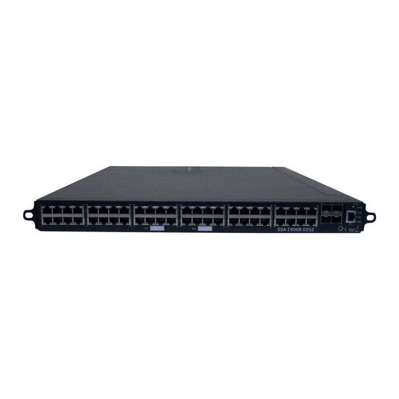
SSA-T1068-0652 SSA-T1068-0652 The SSA‐T1068‐0652 has forty‐eight 10/100/1000BASE‐T RJ45 ports and four 10GBASE‐X SFP+ ports, as shown in Figure 1‐2. Figure 1-2 SSA-T1068-0652 Front Panel 10/100/1000BASE-T RJ45 ports Micro-USB debug port 10GBASE-X SFP+ ports OFFLINE/RESTART button PoE mode button COM port System LEDs Each of the 10/100/1000BASE‐T ports, which support PoE (IEEE 802.3af and 802.3at), can operate in either half‐duplex or full‐duplex mode which can be determined by either auto‐negotiation or manual configuration. The SSA‐T1068‐0652 can provide PoE power for powered devices on all 48 RJ45 ports simultaneously. The SFP+ ports support a number of SFP+ pluggable transceivers. For more information about the transceivers, see the following: http://www.enterasys.com/products/transceivers‐ds.pdf SSA-G1018-0652 The SSA‐G1018‐0652 has forty‐eight 1000BASE‐T SFP ports and four 10GBASE‐X SFP+ ports, as shown in Figure 1‐3. Figure 1-3... -
Page 23: Ac Power Supplies
Redundant – 625 watts (2 x 625) – 625 watts (625 + 1000) – 1000 watts (2 x 1000) • Non‐redundant (additive) – 625 watts (1 x 625) – 1000 watts (1 x 1000) – 1250 watts (2 x 625) – 1625 watts (1000 + 625) – 2000 watts (2 x 1000) For more information, see “Installing the Power Supplies” on page 2‐13. For information on the power supply LEDs, see “Power Supply LEDs” on page 3‐5. Fans The SSA uses thirteen individual 12V fans to cool the system. Though the SSA fans are field replaceable, they are not hot swappable. For information on how to replace SSA fans, see “Replacing the SSA Fans” on page 3‐7. Micro-USB Port The micro‐USB port is intended for debug purposes only. Enterasys S-Series Stand Alone (SSA) Hardware Installation Guide 1-3... -
Page 24: Power Over Ethernet
Power over Ethernet Power over Ethernet Two SSA models—SSA‐T4068‐0252 and SSA‐T1068‐0652—support both IEEE 802.3af and 802.3at Power over Ethernet (PoE) standards, with up to 1500 watts available for PoE. Depending on your power supply configuration, the SSA‐T4068‐0252 and SSA‐T1068‐0652 can supply PoE power to powered devices on all 48 RJ45 ports simultaneously. The red PoE button switches the RJ45 port LEDs to report PoE information. In PoE mode, the PWR LED changes to indicate the power supplies installed in the SSA. For more information, see Table 3‐2 in Chapter 3, Troubleshooting. For an overview of PoE, see Appendix C, About PoE (Power over Ethernet). Management You can manage the SSA either in‐band or out‐of‐band. In‐band remote management is possible ® using the Enterasys Networks’ NetSight management application or the command line interface (CLI) via Telnet. Out‐of‐band management is provided through the RJ45 COM (Communication) port on the front panel using a PC, a VT terminal, or a VT terminal emulator. For more information, see “Connecting to the Network” on page 2‐16. 1-4 Introduction... -
Page 25: Chapter 2: Installation
Read the Release Notes specific to the firmware image running in the chassis to check for any exceptions to the supported features and operation documented in this guide. Required Tools • ESD wrist strap (included with the SSA) • Phillips screwdriver Enterasys S-Series Stand Alone (SSA) Hardware Installation Guide 2-1... -
Page 26: Unpacking The Ssa
Rail kit, which includes right and left rails, rail extensions (installed on the rails), mounting brackets (2), 2-56 screws (2), 10-32 screws (2), and 10-32 cage nuts (2) RJ45 management cable RJ45-to-DB9 converter Anti-static wrist strap Adhesive rubber feet (4) Installation Guide Release Notes Inspect the SSA for any signs of physical damage. If there are any signs of damage, DO NOT install the SSA; instead, contact Enterasys Networks. Refer to “Getting Help” on page xvii for details. 2-2 Installation... -
Page 27: Mounting The Ssa
Warnhinweis: Überzeugen Sie sich vor dem Einbau des Gerätes in das Rack von dessen Stabilität, ansonsten könnten Personenschäden oder Schäden am Gerät die Folge sein. Enterasys S-Series Stand Alone (SSA) Hardware Installation Guide 2-3... -
Page 28: Desktop Installation
Mounting the SSA Desktop Installation For desktop installation, you must attach the adhesive rubber feet to the bottom of the SSA. To attach the rubber feet to the bottom of the SSA: Place the SSA upside down on a sturdy, flat surface. Remove the adhesive backing from the four rubber feet. Adhere the rubber feet to the round, recessed areas on the bottom of the SSA. You can now unpack and install the SSA power supplies. See “Unpacking the Power Supplies” on page 2‐12 and “Installing the Power Supplies” on page 2‐13. Rack Mounting the SSA in a Four-post Rack Notes: If you plan to secure the rear of the SSA to the rails, you must remove the screw in the left rear corner of the SSA BEFORE you install the SSA in the rack. -
Page 29: Attaching The Rails To A Four-Post Rack
Mounting the SSA Attach each rail to the rack posts with two screws in the front and two screws in the back in the top and bottom screw holes. See Figure 2‐1. The SSA rail kit does not include screws for attaching the rails to the rack posts. Figure 2-1 Attaching the Rails to a Four-post Rack If necessary, tighten the screws that secure the rail extensions to the rails. These screws must be tight before you place the SSA in the rails. From the front of the rack, slide the SSA onto the rails until the mounting ears of the SSA are against the front posts of the rack. Enterasys S-Series Stand Alone (SSA) Hardware Installation Guide 2-5... -
Page 30: Securing The Ssa In A Four-Post Rack
Mounting the SSA Secure the front of the SSA to the rack by screwing the customer‐supplied rack screws in the mounting ears on the right and left front of the SSA. See Figure 2‐2. Figure 2-2 Securing the SSA in a Four-post Rack (Optional) Secure the rear of the SSA to the rails. See “Securing the SSA to the Rear of the Rails” on page 2‐11. You can now unpack and install the SSA power supplies. See “Unpacking the Power Supplies” on page 2‐12 and “Installing the Power Supplies” on page 2‐13. 2-6 Installation... -
Page 31: Rack Mounting The Ssa In A Two-Post Rack (7-Inch Posts)
Figure 2-3 Removing the Rail Extensions Rails (used in this procedure) Rail clamps (not used in this procedure) Rail extensions (not used in this procedure) 6-32 screws (used in this procedure) Enterasys S-Series Stand Alone (SSA) Hardware Installation Guide 2-7... -
Page 32: Attaching The Mounting Brackets To The Rails (Left Rail Example)
Mounting the SSA Attach a mounting bracket, included in the SSA rail kit, to the outside of each rail using the 6‐ 32 screws removed in step 1. See Figure 2‐4. Use four 6‐32 screws to attach each mounting bracket. Leave the 6‐32 screws loose to position the mounting brackets properly against the rack posts. Figure 2-4 Attaching the Mounting Brackets to the Rails (Left Rail Example) Mounting bracket Rail Position the right and left rails, which are labeled on the inside of each rail, in the rack with the bottom lip of the rail facing into the rack. The front mounting ears of the rails should be flush against the front screw holes of the rack posts. The mounting brackets should be flush against the rear screw holes of the rack posts. See Figure 2‐5. Figure 2-5 Positioning and Attaching the Rails to the 7-inch Posts Securing the left rail to the front of the 7-inch Securing the left mounting bracket to the rear of post... - Page 33 Mounting the SSA Attach the rails to the rack posts. See Figure 2‐5. Secure the front of the rail to the front of the rack post with customer‐supplied screws in the top and bottom screw holes. b. Secure the mounting bracket to the back of the rack post with customer‐supplied screws in the top and bottom screw holes. The SSA rail kit does not include screws for attaching the rails and mounting brackets to the rack posts. Tighten the 6‐32 screws that secure the mounting brackets to the rails. Slide the SSA onto the rails until the front of the SSA is against the front of the rack posts. Secure the front of the SSA to the rack by screwing the customer‐supplied rack screws in the mounting ears on the right and left front of the SSA. (Optional) Secure the rear of the SSA to the rails. See “Securing the SSA to the Rear of the Rails” on page 2‐11. You can now unpack and install the SSA power supplies. See “Unpacking the Power Supplies” on page 2‐12 and “Installing the Power Supplies” on page 2‐13. Enterasys S-Series Stand Alone (SSA) Hardware Installation Guide 2-9...
-
Page 34: Rack Mounting The Ssa In A Two-Post Rack (3-Inch Posts)
Precaución: Si instala un SSA en un estante de cuatro o de dos postes, debe usar el kit de rieles de SSA para realizar la instalación. No intente asegurar el SSA directamente en el estante usando las lengüetas de montaje delanteras pequeñas. In a two‐post rack with 3‐inch posts, three mid‐mount positions are possible. See Figure 2‐6 for possible mounting positions, as shown on the right post. Enterasys Networks considers the top mid‐mount position shown in Figure 2‐6 to be the best of the three options. Figure 2-6 Installation Positions in a Two-post Rack (3-inch Posts) To rack mount the SSA in a two‐post rack with 3‐inch posts:... -
Page 35: Securing The Ssa To The Rear Of The Rails
Screw to Remove if You Plan to Secure the Left Rear of the SSA Remove this screw before installing the SSA in the rack To secure the rear of the SSA to the rails, screw the 2‐56 screws, included in the SSA rail kit, into the screw tabs on the right and left rail. See Figure 2‐8. Figure 2-8 Securing the Rear of the SSA (Four-post Rack Example) Enterasys S-Series Stand Alone (SSA) Hardware Installation Guide 2-11... -
Page 36: Unpacking The Power Supplies
Unpack the power supply by removing it from the shipping box and sliding the two foam end caps off the unit. Save the shipping box and materials in the event the unit must be reshipped. Verify the contents of the box using Table 2‐2. Remove the power supply from its protective plastic bag. Examine the power supply carefully, checking for damage. If there are any signs of damage, DO NOT install the power supply; instead, contact Enterasys Networks. Refer to “Getting Help” on page xvii for details. Table 2-2 Contents of SSA Power Supply Carton Item Quantity Power supply (SSA-AC-PS-625W or SSA-AC-PS-1000W) For USA shipments: NEMA Power Cord 6-20, C19, R/A, SHLD Type of power cord is dependent on country of installation. -
Page 37: Installing The Power Supplies
Installing the Power Supplies Installing the Power Supplies If you are installing only one power supply, you must put the power supply in the left power supply bay (labeled PS1). The SSA ships without a coverplate on the PS1 bay. To install the power supplies in the SSA: Put on the antistatic wrist strap and attach it to the ground receptacle on the front of the SSA before handling a power supply. Refer to the instructions in the anti‐static wrist strap package. See Figure 2‐9 for the location of the ground receptacle. Figure 2-9 SSA Ground Receptacle Ground receptacle Holding the power supply with the handle on top, align the power supply with the left power supply bay (labeled PS1). Slide the power supply forward until it is plugged into the chassis connector and is completely inside the bay. See Figure 2‐10. Figure 2-10 Installing a Power Supply Enterasys S-Series Stand Alone (SSA) Hardware Installation Guide 2-13... -
Page 38: Powering Up The Ssa
Powering Up the SSA If you are installing a second power supply, remove the coverplate from the right power supply bay by unscrewing the screws that attach the coverplate to the SSA. Keep the coverplate in the event you need to remove the power supply. Repeat steps 2–3 to install the power supply in the right power supply bay. Tighten the captive screws of the power supplies. Powering Up the SSA To connect the SSA to the power sources: Plug a power cord into each power supply’s AC power receptacle. Plug the cord into a dedicated grounded AC outlet as shown in Figure 2‐11. To take advantage of redundancy capabilities, plug each power cord into a separate dedicated AC outlet. (Optional) Secure each power cord to the SSA by tying the power cords to the plastic brackets, adjacent to the power supply bays, with customer‐supplied zip ties. Figure 2-11 Connecting Power to the SSA Plastic brackets for securing AC power cords to the SSA The PWR LED, located on the front panel, turns ON (green) and the CPU LED turns red until the SSA completes its initialization. When the initialization process is successful, the CPU LED turns green. If the CPU LED does not ... -
Page 39: Removing A Power Supply
Precaución: Si desea trabajar sólo con una fuente de poder, no olvide colocar la tapa en el compartimiento de la fuente de poder que haya eliminado, para reducir la interferencia electromagnética y para asegurar una buena ventilación. Enterasys S-Series Stand Alone (SSA) Hardware Installation Guide 2-15... -
Page 40: Connecting To The Network
Link Aggregation to operate properly. Before connecting the cables, refer to the Enterasys S-Series Configuration Guide for the configuration information. For details on how to obtain manuals, refer to “Related Documents”... -
Page 41: Connecting Pluggable Transceivers To The Sfp And Sfp+ Ports
SFP o SFP+ en su bolsa antiestática o en cualquier otro recipiente antiestático. Preparation Before installing the pluggable transceiver, proceed as follows: Put on the antistatic wrist strap and attach it to the ground receptacle on the front of the SSA before removing the pluggable transceiver from the anti‐static packaging. Refer to the instructions in the anti‐static wrist strap package. See Figure 2‐9 on page 2‐13 for the location of the ground receptacle. Remove the pluggable transceiver from the packaging. If there is a protective dust cover on the pluggable transceiver, do not remove it at this time. Installing the Pluggable Transceiver To install an SFP or SFP+ pluggable transceiver in the SSA: Hold the pluggable transceiver so that the connector will seat properly. Carefully align the pluggable transceiver with the port. Push the pluggable transceiver into the port until the pluggable transceiver clicks and locks into place. Enterasys S-Series Stand Alone (SSA) Hardware Installation Guide 2-17... -
Page 42: Connecting To The Com Port For Local Management
Connecting to the COM Port for Local Management Removing the Pluggable Transceiver To remove a pluggable transceiver from a port: Caution: Do NOT remove an SFP or SFP+ from a slot without releasing the locking tab located under the front bottom end of the SFP or SFP+ This can damage the SFP or SFP+. -
Page 43: Connecting To A Vt Series Terminal
Connecting to a VT Series Terminal To connect a VT Series terminal to the SSA COM port, use a UTP cable with RJ45 connectors and an optional RJ45‐to‐DB25 female adapter. Connect the RJ45 connector at one end of the cable to the COM port on the SSA. Plug the RJ45 connector at the other end of the cable into the RJ45‐to‐DB25 female adapter. Connect the RJ45‐to‐DB25 adapter to the port labeled COMM on the VT terminal. Turn on the VT terminal and access the Setup Directory. Set the following parameters: Parameter Setting Mode 7 Bit Control Transmit Transmit=9600 Bits Parity 8 Bits, No Parity Stop Bit 1 Stop Bit When these parameters are set, the Local Management password screen will display. Refer to “Completing the Installation” on page 2‐20 for further information. Enterasys S-Series Stand Alone (SSA) Hardware Installation Guide 2-19... -
Page 44: Adapter Wiring And Signal Assignments
By default, the SSA is configured with three user login accounts: ro for Read-Only access; rw for Read-Write access; and admin for super-user access to all modifiable parameters. The default password is set to blank (null). For information on changing these default passwords, refer to the Enterasys S-Series Configuration Guide 2-20 Installation... - Page 45 (c) Copyright Enterasys Networks, Inc. 2009 Chassis Serial Number: xxxxxxxxxxxx Chassis Firmware Revision: xx.xx.xx SSA (su)-> At the login prompt, enter one of the following default user names: – ro for Read‐Only access – rw for Read‐Write access – admin for Super User access. (This access level allows Read‐Write access to all modifiable parameters, including user accounts.) Press Enter. The Password prompt displays. Leave this string blank and press Enter. The device information and SSA prompt appear as shown above. The SSA is now ready to be configured. For information about setting the IP address and configuring Telnet settings for remote access to SSA management, refer to the Enterasys S‐Series Configuration Guide. The CLI commands enable you to initially set up and perform more involved management configurations. The Enterasys S‐Series Configuration Guide is available online at: http://www.enterasys.com/support/manuals Enterasys S-Series Stand Alone (SSA) Hardware Installation Guide 2-21...
- Page 46 Completing the Installation Pin Out Descriptions 2-22 Installation...
-
Page 47: Chapter 3: Troubleshooting
Refer to page... LEDs Troubleshooting Checklist Replacing the SSA Fans Using the OFFLINE/RESET Button 3-17 LEDs The SSA has port, system, and power supply LEDs. Port LEDs On the SSA, you can view the receive and transmit activity on the RX and TX LEDs for the RJ45, SFP, and SFP+ ports. See Figure 3‐1 and Figure 3‐2. Figure 3-1 RJ45 Port LEDs RX LED TX LED Enterasys S-Series Stand Alone (SSA) Hardware Installation Guide 3-1... -
Page 48: Sfp And Sfp+ Port Leds
None Port enabled, but no activity. If you know the port should (Transmit) be active and is not, contact Enterasys Technical Support. Green (blinking) Indicates data transmission activity. None. Flashing frequency indicates the data rate. -
Page 49: System Leds
The RJ45 port LEDs are in RX/TX mode. None. Table 3-1 on page 3-2. You can switch to or from RX/TX mode by pressing the red POE button next to the POE LED. Enterasys S-Series Stand Alone (SSA) Hardware Installation Guide 3-3... - Page 50 Ensure chassis has adequate power. Amber Blinking. Device in bootup process. None. Solid. Testing. If the LED remains amber for several minutes, contact Enterasys Networks for technical support. Green Blinking. Image starts running. None. Solid. Functional. None. Solid. Processor in reset.
-
Page 51: Power Supply Leds
If the username/password combination has been forgotten, refer beyond Password combination entered. Appendix Resetting Mode Switches for instructions on screen. how to set the mode switch to reset the username/password combination to the default values. Enterasys S-Series Stand Alone (SSA) Hardware Installation Guide 3-5... - Page 52 Persistent Data Reset, was changed Configuration Guide for the instructions to configure the device. and device name, sometime before either cycling If the problem persists, contact Enterasys Networks for technical etc.) were lost power or pressing the RESET support. when the SSA...
-
Page 53: Replacing The Ssa Fans
Warnhinweis: Dieses Gerät hat mehrere Netzanschlüße, trennen Sie vor den Wartungsarbeiten beide Netzanschlüsse vom Versorgungsnetz. zum Schutz vor elektrischen Schlägen. The SSA is cooled by thirteen individual 12V fans. If the FAN LED and the output of the CLI show system command indicate that a fan has failed, you must replace the failed fan. Enterasys S-Series Stand Alone (SSA) Hardware Installation Guide 3-7... -
Page 54: Ssa Fan Locations
Replacing the SSA Fans The thirteen SSA fans are divided into three groups (see Figure 3‐4): • Fans F1–F7, which are located on the right side of the SSA. Each F1–F7 fan’s connector is adjacent to the fan. See “Replacing Fans F1–F7” on page 3‐9. • Fans F8–F10, which, like fans F1–F7, are located on the side of the SSA; however, fans F8–F10 do not have adjacent connectors—they are located behind fan F7. See “Replacing Fans F8– F10” on page 3‐12. • Fans F11–F13, which are located in the rear of the SSA, between the power supply bays. Like fans F8–F10, fans F11–F13 do not have adjacent connectors. See “Replacing Fans F11–F13” on page 3‐14. Figure 3-4 SSA Fan Locations Fans F1–F7 Fans F8–F10 Fans F11–F13 Before replacing any of the SSA fans, you must first power down the SSA and, if installed in an equipment rack, remove the SSA from the rack. The replacement fan kit, SSA‐FAN‐KIT, which you must order separately, contains one replacement fan. 3-8 Troubleshooting... -
Page 55: Replacing Fans F1-F7
Replacing the SSA Fans Replacing Fans F1–F7 To replace an F1–F7 fan: Put on the ESD wrist strap and attach it to the ground receptacle on the front of the SSA. Remove the side panel from the SSA by unscrewing the eight zinc (silver) screws from the side panel. See Figure 3‐5. Figure 3-5 Removing the Side Panel of the SSA Enterasys S-Series Stand Alone (SSA) Hardware Installation Guide 3-9... -
Page 56: Underside Of The Ssa Side Panel
Replacing the SSA Fans Set the side panel upside down to view the label on the inside of the side panel that indicates the position of each fan. See Figure 3‐6. Figure 3-6 Underside of the SSA Side Panel Remove the failed fan from its position in the SSA. Disconnect the failed fan from its connector, located to the right of the fan. See Figure 3‐7. Figure 3-7 Disconnecting an F1–F7 Fan (Fan F3 Example) Fan F3 connector Fan F3 3-10 Troubleshooting... -
Page 57: Connecting An F1-F7 Fan (Fan F3 Example)
Replacing the SSA Fans To ensure proper air flow, connect the new fan to the chassis connector with the label side of the replacement fan facing into the SSA and the cable clip on the right. See Figure 3‐8. Do not remove the cable clip on fans F1–F7. See Figure 3‐9 on page 3‐12, which shows the cable clip. Figure 3-8 Connecting an F1–F7 Fan (Fan F3 Example) Fan F3 connector Fan F3 (label facing into the SSA) Place the fan in the chassis next to the connector. See Figure 3‐8. Reinstall the side panel of the SSA. You can now reinstall the SSA in the equipment rack. Enterasys S-Series Stand Alone (SSA) Hardware Installation Guide 3-11... -
Page 58: Replacing Fans F8-F10
Replacing the SSA Fans Replacing Fans F8–F10 To replace an F8–F10 fan: Put on the ESD wrist strap and attach it to the ground receptacle on the front of the SSA. Remove the side panel from the SSA by unscrewing the eight zinc (silver) screws from the side panel. See Figure 3‐5 on page 3‐9. Set the side panel upside down to view the label on the inside of the side panel that indicates the position of each fan. See Figure 3‐6 on page 3‐10. Disconnect and remove fan F7 to access the F8–F10 bank of connectors, located behind fan F7. See Figure 3‐10 on page 3‐13, which shows the connectors for the F8–F10 fans. Lift the failed fan out of the chassis. Disconnect the failed fan from the appropriate connector. – F8 connector: left connector – F9 connector: middle connector – F10 connector: right connector Unwind the replacement fan’s cables. Remove the cable clip from the replacement fan. See Figure 3‐9. You may discard the cable clip. Figure 3-9 Removing a Fan’s Cable Clip Fan cables Cable clip 3-12 Troubleshooting... -
Page 59: Connecting An F8-F10 Fan (Fan F8 Example)
3‐10. Figure 3-10 Connecting an F8–F10 Fan (Fan F8 Example) Fan F8 connector F8–F10 cable management clip Fan F8 Feed the excess fan cable into the cable management clip. See Figure 3‐10. 11. Position the cables of the F8–F10 fans on the floor of the SSA. 12. Position the F8–F10 fans on top of their cables. 13. Reinstall fan F7. 14. Reinstall the side panel of the SSA. You can now reinstall the SSA in the equipment rack. Enterasys S-Series Stand Alone (SSA) Hardware Installation Guide 3-13... -
Page 60: Removing The Rear Panel
Replacing the SSA Fans Replacing Fans F11–F13 To replace an F11–F13 fan: Put on the ESD wrist strap and attach it to the ground receptacle on the front of the SSA. Remove the rear panel of the SSA by unscrewing the four zinc (silver) screws from the rear panel. See Figure 3‐11. Figure 3-11 Removing the Rear Panel 3-14 Troubleshooting... -
Page 61: Underside Of The Ssa Rear Panel
Replacing the SSA Fans Set the side panel upside down to view the label on the inside of the rear panel that indicates the position of each fan. See Figure 3‐12. Figure 3-12 Underside of the SSA Rear Panel Remove the failed fan from the SSA. See Figure 3‐13. Lift the failed fan out the SSA. Figure 3-13 Disconnecting an F11–F13 Fan (Fan F11 Example) Fan F11 connector Fan F11 Rubber grommet Enterasys S-Series Stand Alone (SSA) Hardware Installation Guide 3-15... -
Page 62: Connecting An F11-F13 Fan (Fan F11 Example)
Replacing the SSA Fans b. Remove the failed fan’s cables from the rubber grommet. You may have to lift the rubber grommet out of the chassis to remove the failed fan’s cables from the grommet. The grommet is slit. Disconnect the fan from the appropriate connector. The bank of F11–F13 connectors is located next to fan F11, on the other side of the sheet metal wall that separates the power supply bays from the rest of the SSA. If you are facing towards the back of the SSA, the F11–F13 connectors are arranged as follows: ‐ F11 connector: left connector ‐ F12 connector: middle connector ‐ F13 connector: right connector Unwind the replacement fan’s cables. Remove the cable clip from the replacement fan. See Figure 3‐9 on page 3‐12. You may discard the cable clip. With the label side of the replacement fan facing into the second power supply bay (labeled PS2) and the cable on the left, slip the fan cable into the rubber grommet and connect the cable to the chassis connector. See Figure 3‐14. Figure 3-14 Connecting an F11–F13 Fan (Fan F11 Example) Fan F11 connector Fan F11 Rubber grommet Position the fan in the SSA. ... -
Page 63: Using The Offline/Reset Button
Precaución: No se recomienda utilizar este método para apagar los módulos SSA. Recurra a él sólo como último recurso, puesto que interrumpe todos los procesos del módulo en funcionamiento, lo que podría resultar pérdidas de frames. To reset an SSA without it performing an orderly shutdown routine, press and hold the OFFLINE/ RESET button for approximately 6 seconds. Enterasys S-Series Stand Alone (SSA) Hardware Installation Guide 3-17... - Page 64 Using the OFFLINE/RESET Button 3-18 Troubleshooting...
-
Page 65: Appendix A: Specifications
4.44 cm H x 44.70 cm W x 59.43 cm D 1.75” H x 17.60” W x 23.40” D Approximate Weight Gross: 11.79 kg (26 lb) Mean Time Between Failure (MTBF) Refer to the MTBF web site at URL http://www.enterasys.com/support/mtbf/ Enterasys S-Series Stand Alone (SSA) Hardware Installation Guide A-1... -
Page 66: Pluggable Transceiver Specifications
5°C to 40°C (41°F to 104°F) Storage Temperature -30°C to 73°C (-22°F to 164°F) Operating Relative Humidity 5% to 95% (non-condensing) Pluggable Transceiver Specifications For SFP and SFP+ transceiver specifications, refer to the datasheet at the following URL: http://www.enterasys.com/products/transceivers‐ds.pdf COM Port Pinout Assignments The COM port is an RJ45 communications port for local access to local management. Refer to the table below for the COM port pin assignments. Table A-2 COM Port Pin Assignments Signal Name Input/Output... -
Page 67: Regulatory Compliance
(Class A), EN 55024, EN 61000-3-2, EN 61000-3-3, AS/NZ CISPR-22 (Class A). VCCI V-3. CNS 13438 (BSMI), 2004/108/EC (EMC Directive) Environmental 2002/95/EC (RoHS Directive), 2002/96/EC (WEEE Directive), Ministry of Information Order #39 (China RoHS) Enterasys S-Series Stand Alone (SSA) Hardware Installation Guide A-3... - Page 68 Regulatory Compliance A-4 Specifications...
-
Page 69: Appendix B: Resetting Mode Switches
Warnhinweis: Dieses Gerät hat mehrere Netzanschlüße, trennen Sie vor den Wartungsarbeiten beide Netzanschlüsse vom Versorgungsnetz. zum Schutz vor elektrischen Schlägen. Enterasys S-Series Stand Alone (SSA) Hardware Installation Guide B-1... -
Page 70: Required Tools
Precaución: Si desea modificar la configuración del interruptor, lea las secciones correspondientes para saber cuál será el resultado de hacerlo. Estas modificaciones a la configuración sólo debe realizarlas personal calificado. Figure B‐1 on page B‐3 shows the locations of the mode switches and the switch settings for normal operation. These switches are set at the factory and rarely need to be changed. Switch definitions and positions are as follows: • Switches 1– 6: For Enterasys Networks use only. • Switch 7: Clear Persistent Data. Changing the position of this switch clears Persistent Data on the next power‐up of the SSA. All user‐entered parameters, such as the IP address, system name, and so on, are reset to the factory default settings. Once the system resets, you can either use the factory default settings or reenter your own parameters. • Switch 8: Clear Admin Password. Changing the position of this switch clears the admin ... -
Page 71: Mode Switch Location
About the Mode Switches Figure B-1 Mode Switch Location Switch 8 Switch 7 Enterasys S-Series Stand Alone (SSA) Hardware Installation Guide B-3... -
Page 72: Setting The Mode Switches
Setting the Mode Switches Setting the Mode Switches Before setting the mode switches, you must power down the SSA. Put on the ESD wrist strap and attach it to the ground receptacle on the front of the SSA. Remove the rear panel of the SSA by unscrewing the four zinc (silver) screws from the rear panel. See Figure B‐2. Figure B-2 Removing the Rear Panel Reset the appropriate switch. Replace the rear panel of the SSA. B-4 Resetting Mode Switches... -
Page 73: Appendix C: About Poe (Power Over Ethernet)
Default 0.44 to 12.95 Watts Optional 0.44 to 3.84 Watts Optional 3.84 to 6.49 Watts Optional 6.49 to 12.95 Watts Not Allowed Reserved for Future Use Proprietary PD Detection S‐Series devices support a subset of the currently deployed proprietary PoE methods. This includes support for Cisco PDs, including a proprietary capacitor based detection scheme. Enterasys S-Series Stand Alone (SSA) Hardware Installation Guide C-1... -
Page 74: Poe Port Status Leds
The power available for PoE is distributed based on the configured allocation mode: • Automatic mode (default), in which available power is distributed evenly. Any change in available power, due to a change in power supply status or redundancy mode, will trigger an automatic redistribution of power. • Manual mode, in which the power budget is manually configured, using either CLI commands or the MIBs. The wattage configured cannot exceed the total power available on the switch for PoE. The configured wattage assignment is used to calculate the total available PoE power. If the total available PoE power changes, a redistribution of available power will occur, applying the calculated percentage. If the PoE power needed or requested exceeds the power available, the system will generate an SNMP trap to notify the system manager. For more information on configuring allocation mode, see the Enterasys S‐Series CLI Reference Guide. Power Distribution Upon Power Supply Removal or Addition When a power supply is removed, the SSA responds to the decrease in available power by doing the following: Detecting the power supply removal and recalculating available power. Subtracting the power capacity for its base system from available power. Distributing remaining power equally for PoE. Dropping support to PoE devices as necessary to stay within the programmed maximum power. When a power supply is added, the SSA responds to the increase in available power by doing the following: Detecting the power supply addition and recalculating available power. Subtracting the power capacity for its base system from available power. Distributing remaining power equally for PoE. C-2 About PoE (Power over Ethernet) -
Page 75: Management Of Poe Power To Pds
Management of PoE Power to PDs Management of PoE Power to PDs You can configure how the SSA makes power available to attached powered devices (PDs): • Real‐time mode (default), in which the PoE controller calculates the power needed by a PD based on the actual power consumption of the attached devices. • Class mode, in which the PoE controller manages power based on the IEEE 802.3at definition of the class limits advertised by the attached devices. In this mode, the maximum amount of power required by a device in the advertised class is reserved for the port, regardless of the actual amount of power being used by the device. For more information on configuring power management mode, see the Enterasys S‐Series CLI Reference Guide. Enterasys S-Series Stand Alone (SSA) Hardware Installation Guide C-3... - Page 76 Management of PoE Power to PDs C-4 About PoE (Power over Ethernet)
Need help?
Do you have a question about the SSA-T1068-0652 and is the answer not in the manual?
Questions and answers