Table of Contents
Advertisement
Copyright and Warranty Notice
The information in this document is subject to change without notice and does not
represent a commitment on part of the vendor, who assumes no liability or
responsibility for any errors that may appear in this manual.
No warranty or representation, either expressed or implied, is made with respect to the
quality, accuracy or fitness for any particular part of this document. In no event shall
the manufacturer be liable for direct, indirect, special, incidental or consequential
damages arising from any defect or error in this manual or product.
Product names appearing in this manual are for identification purpose only and
trademarks and product names or brand names appearing in this document are the
property of their respective owners.
This document contains materials protected under International Copyright Laws. All
rights reserved. No part of this manual may be reproduced, transmitted or transcribed
without the expressed written permission of the manufacturer and authors of this
manual.
If you do not properly set the motherboard settings, causing the motherboard to
malfunction or fail, we cannot guarantee any responsibility.
Advertisement
Table of Contents

Related Manuals for Abit IT7-MAX2


Summary of Contents for Abit IT7-MAX2
- Page 1 Copyright and Warranty Notice The information in this document is subject to change without notice and does not represent a commitment on part of the vendor, who assumes no liability or responsibility for any errors that may appear in this manual. No warranty or representation, either expressed or implied, is made with respect to the quality, accuracy or fitness for any particular part of this document.
-
Page 3: Table Of Contents
IT7-MAX2 Motherboard User’s Manual Index IT7-MAX2 快速安裝指引..................1 IT7-MAX2 クイックインストールガイド ............5 IT7-MAX2 Schnellinstallationsanleitung ............9 IT7-MAX2 Guide d’Installation Rapide............13 Краткое руководство по установке IT7-MAX2...........17 Guida all’installazione veloce Scheda madre IT7-MAX2 ......21 CHAPTER 1. INTRODUCTION..............1-1 1-1...............1-1 EATURES AND PECIFICATIONS 1-2..................1-3 AYOUT IAGRAM CHAPTER 2. - Page 4 APPENDIX F. BIOS UPDATE GUIDE ............F-1 APPENDIX G. HARDWARE MONITORING (THE WINBOND HARDWARE DOCTOR UTILITY) ........G-1 APPENDIX H. INSTALLATION GUIDE FOR SUSPEND TO RAM..H-1 APPENDIX I. TROUBLESHOOTING (NEED ASSISTANCE?)....I-1 APPENDIX J. HOW TO GET TECHNICAL SUPPORT ......J-1 IT7-MAX2...
-
Page 5: It7-Max2 快速安裝指引
快速安裝指引 IT7-MAX2 IT7-MAX2 快速安裝指引 感謝您購買 ABIT 的主機板,此主機板是設計給 Intel Socket 478 Pentium 4 處理器使用。支援 Intel Socket-478 架構的處理器,並支援最高至 2GB 容量的 DDR 記憶體模組。 如您要瞭解此主機板更詳細的資訊,請參閱我們的完整版使用手冊,裡面會有詳盡的說明。此快速 安裝手冊是給有經驗的系統組裝者使用,如果這是您第㆒次嘗試來組裝您的電腦系統,我們建議您 先去閱讀完整版的使用手冊,或是詢問技術㆟員來幫助您組裝您的電腦系統。 IT7-MAX2 主機板主要元件配置圖 使用手冊... - Page 6 快速安裝指引 IT7-MAX2 處理器的安裝 若您置入處理器的方向不對,您將無法輕易 ㆞將處理器插入 Socket 478 插座 , 而且處理器 的針腳將無法完全進入腳座。如果發現有這 種現象時,請您改變處理器的方向,直到它 能輕易且完全插入 Socket 478。同時您必需檢 視處理器溫度偵測熱敏電阻的高度(如果有 的話),然後再小心的將 Intel Pentium 4 處理 器安裝到 Socket 478 腳座㆖去。 安裝散熱器與散熱風扇是必需的,那樣可以 讓您的處理器適當㆞散熱。未安裝這些散熱 裝置可能導致處理器過熱並且會損壞您的處 理器。Intel Socket 478 處理器在運作時會產生 大量的熱量,所以您需要使用專門為 Intel Socket 478 處理器設計的大型散熱風扇。否 則,可能導致過熱且會損壞您的處理器。處 理器風扇未裝置妥當並且風扇電源線尚未連 接妥當之前,請不要把 ATX 電源供應器的電...
- Page 7 快速安裝指引 IT7-MAX2 將主機板安裝到機殼㆖ 當您將處理器安裝到主機板㆖之後,您便可以開始將主機板固定到電腦機殼裡去。首先;請您先將 主機板固定到電腦機殼。大多數的電腦機殼底座都有許多的固定孔位,請將主機板㆖的固定孔位與 機殼底座㆖的固定孔位對準。如果孔能對準並且有螺絲孔,就表示可使用銅柱來固定主機板。另外; 您可以使用塑膠墊片來讓螺絲與主機板的 PCB 表層隔離(絕緣)。 安裝系統記憶體 本主機板提供 3 組 184 腳的 DDR DIMM 插座可供記憶體擴充,可支援 DDR SDRAM 的最小記憶 體大小為 64MB,而最大的記憶體大小則為 2GB。 將 DDR DIMM 記憶體模組插入 DIMM 插 槽。請注意記憶體模組的楔子是如何對應到 DIMM 插槽㆖的卡榫之㆖。此種設計可確保 DDR DIMM 記憶體模組僅能由㆒個方向插到 DIMM 插槽之㆖。當您將 DDR DIMM 記憶體...
- Page 8 快速安裝指引 IT7-MAX2 將電源供應器的電源線連接頭與主機板㆖的 ATX1/ATXPR1 連接頭連接起來 請將電源供應器的 ATX 電源接頭確實㆞壓入主機板㆖ 的 ATX1/ATXPR1 接頭,並確定連接妥當。 註:請注意針腳的位置及方向。 處理器參數的設定 當您將所有的硬體安裝完畢以後,就可以開啟電腦的電源並進入 BIOS 的選項。如您想要瞭解相關 且更為詳細的資訊,請參閱我們的完整版使用手冊,裡面會有詳盡的說明。 IT7-MAX2...
-
Page 9: It7-Max2 クイックインストールガイド
クイックインストールガイド IT7-MAX2 IT7-MAX2 クイックインストールガイド ABIT マザーボードをお買い上げいただきましてありがとうございます。このマザーボードは Intel Socket 478 Pentium 4 プロセッサ用に設計されています。最高 2GB の DDR メモリを搭載し た Intel Socket-478 構造をサポートします。 このマザーボードの詳細については、 ユーザーズマニュアルの完全版を参照してください。 この クイックインストールガイドは、 経験あるシステム構築者向けに書かれました。 今回始めてコン ピュータシステムをセットアップする方は、 まず完全版のマニュアルをお読みになるか、 専門技 術者に連絡してコンピュータシステムのセットアップを行うようお勧めします。レバー IT7-MAX2 マザーボードの配置 ユーザーマニュアル... - Page 10 クイックインストールガイド IT7-MAX2 プロセッサの取り付け 方向を間違えて差し込むと、プロセッサは スムーズに入っていかず、途中で止まって しまいます。この場合、向きを変えると、 Socket 478 に完全に差し込まれます。 同時に、 プロセッサの温度検出サーミスタの高さも チェックしてください(マザーボードにこ のコンポーネントが搭載されている場合)。 その後で、 プロセッサを Socket 478 にゆっく り差し込むことができます。 ヒートシンクと冷却ファンの取り付けは、 コンピュータから熱を分散させるために必 要となります。これらのアイテムを取り付 けないと、過熱してプロセッサが破損する 原因となります。 Intel Socket 478 プロセッサ は動作中に高熱を発生するため、 Intel Socket 478 プロセッサ用に特別に設計された大き なヒートシンクが必要となります。そうで ないと、過熱してプロセッサが破損するこ ともあります。プロセッサファンとその電 源ケーブルを正しく取り付けるまでは、 ATX 電源ケーブルをマザーボードに決して 差し込まないでください。これにより、プ...
- Page 11 クイックインストールガイド IT7-MAX2 マザーボードをシャーシに取り付ける マザーボードにプロセッサを取り付けた後、 シャーシにマザーボードを固定することができるよ うになります。まず、シャーシにマザーボードを固定する必要があります。ほとんどのコンピュ ータシャーシには、 多くの取り付け穴の付いた台が付属しており、 それを使用することでマザー ボードをしっかり取り付けたり、 同時にショートを避けることができます。 シャーシに付属する 飾りボタンかスペーサーを使用してマザーボードを固定します。 システムメモリの取り付け このマザーボードでは、3 つの 184 ピン DDR DIMM スロットメモリ拡張を提供します。最小メ モリは 64 MB で、最大メモリは 2GB DDR SDRAM です。 DDR DIMM を図に示すように拡張スロット に差し込みます。モジュールがソケットに どのように固定されているか注意してくだ さい。これにより、DDR DIMM モジュール に差し込む方法が 1 つしかないことを確認...
- Page 12 クイックインストールガイド IT7-MAX2 電源コネクタを ATX1/ATXPR1 コネクタに差し込む 電源装置から出ている電源ブロックコネクタをこの ATX1/ATXPR1 に接続します。コネクタが十分奥まで 装着されていることをご確認ください。 注意:ピンの位置と方向を良く確認してください。 BIOS のセットアップ ハードウェアの取り付けが完了したら、コンピュータの電源をオンにし、BIOS Setup アイテム に移動して、プロセッサのパラメータをセットアップします。詳細については、ユーザーズマニ ュアルの完全版を参照してください。 IT7-MAX2...
-
Page 13: It7-Max2 Schnellinstallationsanleitung
IT7-MAX2 Schnellinstallationsanleitung IT7-MAX2 Schnellinstallationsanleitung Vielen Dank für Ihren Kauf der ABIT-Hauptplatine. Diese Hauptplatine wurde für Intel Socket 478 Pentium Prozessore ausgelegt. unterstützt Intel Socket-478-Struktur DDR-Speichersteckplätze mit der Kapazität von bis zu 2 GB RAM. Beziehen Sie sich bitte für detaillierte Informationen über diese Hauptplatine auf die vollständige Version des Benutzerbuchs. - Page 14 IT7-MAX2 Schnellinstallationsanleitung Installieren des Prozessors Wenn Sie beim Einstecken des Prozessors eine falsche Richtung gewählt haben, kann der Prozessor nicht leicht und komplett eingesteckt werden. Ändern Sie bitte in diesem Fall die Richtung, bis der Prozessor sich leicht und komplett in den Socket 478 einpassen lässt.
- Page 15 IT7-MAX2 Schnellinstallationsanleitung Installieren der Hauptplatine im Gehäuse Nach der Installation des Prozessors können Sie anfangen die Hauptplatine im Computergehäuse zu befestigen. Die meisten Gehäuse haben eine Bodenplatte, auf der sich eine Reihe von Befestigungslöcher befinden, mit deren Hilfe Sie die Hauptplatine sicher verankern können und zugleich Kurzschlüsse verhindern.
- Page 16 IT7-MAX2 Schnellinstallationsanleitung Verbinden der Netzstecker mit dem ATX11/ATXPR1-Anschluss Denken Sie daran, den Anschluss des ATX-Netzteils fest in das Ende mit dem ATX1/ATXPR1-Anschluss zu drücken, um eine feste Verbindung zu garantieren. Hinweis: Achten Sie auf die richtige Ausrichtung und Position der Pole.
-
Page 17: It7-Max2 Guide D'installation Rapide
IT7-MAX2 Guide d’Installation Rapide IT7-MAX2 Guide d’Installation Rapide Merci d’avoir acheté la carte mère ABIT. Cette carte mère est conçue pour les processeurs Intel Pentium 4 Socket 478. Elle supporte la structure Socket-478, avec jusqu’à 2 GB de mémoire DDR. - Page 18 IT7-MAX2 Guide d’Installation Rapide Installer le Processeur La figure vous montre à quoi ressemble l’emplacement Socket 478, comment soulever le levier. Si vous le mettez dans un mauvais sens, vous ne pourrez pas insérer le processeur facilement, et les broches du processeur n’entreront pas entièrement dans...
- Page 19 IT7-MAX2 Guide d’Installation Rapide Installer la Carte Mre dans le Châssis Une fois que vous aurez installé le processeur sur la carte mère, vous pourrez commencer à fixer la carte mère sur le châssis. Tout d’abord, vous avez besoin de fixer la carte mère sur le châssis. La plupart des châssis d’ordinateur possèdent une base sur laquelle il y a nombreux trous de montage permettant à...
- Page 20 IT7-MAX2 Guide d’Installation Rapide Brancher les connecteurs d'alimentation dans les connecteurs ATX1/ATXPR1 Souvenez-vous que vous devez pousser le connecteur de votre alimentation fermement dans connecteur ATX1/ATXPR1 pour assurer une bonne connexion. Remarque: Faites attention à la position des broches et à...
-
Page 21: Краткое Руководство По Установке It7-Max2
Краткое руководство по установке IT7-MAX2 Краткое руководство по установке IT7-MAX2 Благодарим вас за приобретение материнской платы производства ABIT. Эта материнская плата предназначена для использования с процессорами Intel Socket 478. Она поддерживает структуру Intel Socket 478, максимальный объем памяти DDR составляет 2 Гбайт. - Page 22 Краткое руководство по установке IT7-MAX2 Установка процессора Если рычаг будет смещен не в нужную сторону, легко установить процессор не удастся, а контакты процессора не попадут в гнезда. Если так получилось, измените направление перемещения, до тех пор, пока процессор не станет на свое место в гнездо...
- Page 23 Краткое руководство по установке IT7-MAX2 Установка материнской платы в корпус После установки процессора на материнскую плату можно начинать установку материнской платы в корпус. Большая часть корпусов оборудована основанием, в котором проделаны монтажные отверстия, которые позволяют надежно закрепить материнскую плату и предотвратить...
- Page 24 Краткое руководство по установке IT7-MAX2 Подключение кабелей питания к разъемам ATX1/ATXPR1 Обратите внимание, разъем блока питания ATX необходимо вставить в разъем ATX1/ATXPR1 до упора, чтобы обеспечить надежное соединение. Примечание: Обратите внимание на положение контактов и ориентацию разъема. Настройка BIOS По окончании установки аппаратуры включите питание и перейдите в меню BIOS Setup, чтобы...
-
Page 25: Guida All'installazione Veloce Scheda Madre It7-Max2
Guida all’installazione veloce Scheda madre IT7-MAX2 Guida all’installazione veloce Scheda madre IT7-MAX2 Complimenti per l’acquisto di una scheda madre ABIT. Questa scheda madre è progettata per processori Intel Pentium 4. Supporta la struttura Socket 478 con fino a 2GB di memoria DDR. - Page 26 Guida all’installazione veloce Scheda madre IT7-MAX2 Installazione del processore Se il processore è collocato nella posizione sbagliata, non si sarà in grado di inserirlo con facilità riuscirà inserirlo completamente nella presa. In questo caso cambiare la posizione – direzione finché il processore si inserisce completamente e con facilità...
- Page 27 Guida all’installazione veloce Scheda madre IT7-MAX2 Installazione della scheda madre sul telaio Dopo avere installato il processore sulla scheda madre si può iniziare a fissare la scheda madre sul telaio. Innanzi tutto è necessario fissare la scheda madre al telaio. La maggior parte dei telai ha una base sulla quale sono presenti diversi fori di montaggio che permettono di fissare in modo accurato la scheda madre e, allo stesso tempo, di prevenire corto circuiti.
- Page 28 Guida all’installazione veloce Scheda madre IT7-MAX2 Collegamento dei connettori d’alimentazione ai connettori ATX1/ATXPR1 Ricordarsi che è necessario spingere con fermezza fino in fondo il connettore della sorgente d’alimentazione ATX al connettore ATX1/ATXPR1, assicurando così un buon collegamento. Nota: Prestare attenzione...
-
Page 29: Chapter 1. Introduction
Introduction Chapter 1. Introduction 1-1. Features and Specifications 1. CPU ® Supports Intel Pentium 4 socket 478 processor 400MHz/533MHz System Data Bus 2. Chipset Intel 82845E (MCH) + 82801DB (ICH4) Supports AGP 4X 1.5V device only Supports Ultra ATA/100/66/33 mode 3. - Page 30 Onboard debug card design with 7-segment display The Switching Power Supply must meet ATX 2.03 specification with ATX12V and AUX Power connectors. Specifications and information contained herein are subject to change without notice. IT7-MAX2...
-
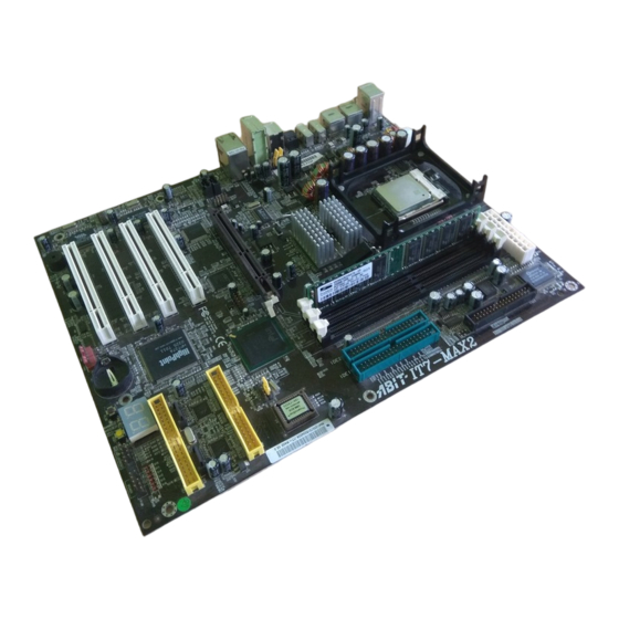
Page 31: Layout Diagram
Introduction 1-2. Layout Diagram User’s Manual... - Page 32 Chapter 1 IT7-MAX2...
-
Page 33: Chapter 2. Hardware Setup
Hardware Setup Chapter 2. Hardware Setup ® It is required to adopt an ATX12V power supply to meet the power requirement of Pentium This motherboard provides all standard equipment for classic personal computers with great flexibility for meeting future upgrade demands. This chapter will introduce step-by-step all of the standard equipment and will also present, as completely as possible, future upgrade capabilities. -
Page 34: Install Pentium ® 4 Cpu And Heatsink Supporting -Base
ATTENTION: Do not forget to set the correct bus frequency and multiple for your processor. Figure 2-3. Installing P4 Socket 478 CPU and its heatsink into supporting base. IT7-MAX2... -
Page 35: Install System Memory
Hardware Setup 2-3. Install System Memory This motherboard provides three 184-pin DDR DIMM sites for memory expansion available from minimum memory size of 64MB to maximum memory size of 2GB DDR SDRAM (DIMM2 & DIMM3 are sharing). In order to create a memory array, certain rules must be followed. The following set of rules allows for optimum configurations. -
Page 36: Connectors, Headers And Switches
ATX12V: ATX Power Input Connectors The Pentium 4 requires a power supplier different from the regular one. It’s a newly designed ATX12V power with 300W, 20A +5VDC capacity at least for heavily loaded system, and 720mA +5VSB at least for supporting Wake-On-LAN feature. IT7-MAX2... - Page 37 Hardware Setup (2). FAN Connectors: FAN1: Power Fan FAN2: CPU Fan FAN3: Spare (No monitor function) FAN4: Spare (No monitor function) FAN5: Chassis Fan (3). CCMOS1: CMOS Memory Clearing Header This header uses a jumper to clear the CMOS memory. Short pin 2 and pin 3 only when you want to clear the CMOS memory.
- Page 38 You can attach one end of a two-threaded thermal cable to this header, and attach the other end of the thermal cable onto any heat source, such as VGA chipset’s heatsink, or Hard Disk Drive. IT7-MAX2...
- Page 39 Hardware Setup (6). FPIO2: Front panel audio connection header This header provides the connection to audio connector at front panel. • To use the audio connector at front panel, remove all the jumpers on this header, and then connect to front panel via an extension cable. •...
- Page 40 This motherboard provides totally six USB 2.0 ports controlled by ICH4. Four of them are through the onboard USB1 and USB2 connectors; two of them are capable through this header. Pin Number Pin Assignment Pin Number Pin Assignment Data0 - Data1 - Data0 + Data1 + Ground Ground FPIO4 Header IT7-MAX2...
- Page 41 Hardware Setup (9). FPIO5: Additional USB Port Header This motherboard also provides totally four extra USB 2.0 ports controlled by VIA VT6202. Two of them are through the onboard LAN/USB connectors; two of them are capable through this header. Pin Number Pin Assignment Pin Number Pin Assignment Data0 - Data1 - Data0 +...
- Page 42 POST item, it will write the corresponding POST Code into the address 80h. If the POST passes, the BIOS will process the next POST item and write the next POST Code into the address 80h. If the POST fails, we can check the POST Code in address 80h to find out where the problem lies. IT7-MAX2...
- Page 43 Hardware Setup 2-11 The following table shows the POST Code in detail: POST Description Code Test CMOS R/W functionality Early chipset initialization: -Disable shadow RAM -Disable L2 cache (socket 7 or below) -Program basic chipset registers Detect memory -Auto-detection of DRAM size, type and ECC -Auto-detection of L2 cache (socket 7 or below) Expand compressed BIOS code to DRAM Call chipset hook to copy BIOS back to E000 &...
- Page 44 2. Initialize Init_Onbaord_AUDIO switch Okay to enter Setup utility; i.e. not until this POST stage can users enter the CMOS setup utility Initialize PS/2 Mouse Prepare memory size information for function call: INT 15h ax=E820h Turn on L2 cache IT7-MAX2...
- Page 45 Hardware Setup 2-13 Program chipset registers according to items described in Setup & Auto-configuration table 1. Assign resources to all ISA PnP devices 2. Auto assign ports to onboard COM ports if the corresponding item in Setup is set to “AUTO”...
- Page 46 Connects to the Power Switch cable of chassis front panel. • Pin 16-20: PWR-LED Connects to the Power LED cable of chassis front panel. • Pin 22-24: KEYLOCK Connects to the Keylock cable (if there is one) of chassis front panel. IT7-MAX2...
- Page 47 Hardware Setup 2-15 (14). AGP1: Accelerated Graphics Port Slot This slot supports an optional AGP graphics card up to AGP 4X mode. Please refer to our Web site for more information on graphics cards. (15). FDC1 Connector There are 34 wires and two connectors on each floppy cable providing two floppy disk drives connection. Connect the single end at the longer length of ribbon cable to this FDC1, and the two connectors on the other end to the floppy disk drives.
- Page 48 IDE3 ~ IDE4 are extra devices controlled by a HighPoint HPT374 chipset. This bonus feature allows for having regular Ultra ATA/133 devices ports, or a RAID array in the combination of RAID 0, RAID 1, or RAID 0+1 mode. IT7-MAX2...
- Page 49 Hardware Setup 2-17 (17). D17/D18: Status Indicator • D17 (5VSB): Stand By LED Indicator This LED lights up when the power supply is connected with power source. • D18 (VCC): Power on Indicator This LED lights up when the system power is on. (18).
- Page 50 F.L./F.R. (Front Left / Front Right): Connects to the front left and front right channel in the 5.1-channel or regular 2-channel audio system. • LAN/USB LAN: Connect your system to Local Area Network through this connector. USB: These two connectors provide USB 2.0 ports controlled by VIA VT6202. IT7-MAX2...
-
Page 51: Chapter 3. Bios Setup
BIOS Setup Chapter 3. BIOS Setup The BIOS is a program located on a Flash Memory chip on the motherboard. This program will not be lost when you turn the computer off. This program is also referred to as the boot program. It is the only channel the hardware circuit has to communicate with the operating system. -
Page 52: Cpu Setup [Softmenu Iii]
CPU Name Is: Intel Pentium (R) 4. CPU Internal Frequency: 2.266GHz (depending on the CPU type). ECC Data Integrity Mode: This item displays the status of DRAM type the system support. For using ECC type, you have to install IT7-MAX2... - Page 53 BIOS Setup one pair of DRAM both of ECC type. A different type, like one ECC and one Non-ECC, will leave this item as Unsupported. CPU Operating Speed: This option sets the CPU speed. In this field, the CPU speed is indicated like this: CPU Speed = External Clock x Multiplier Factor.
- Page 54 This item selects the CPU core voltage. ATTENTION: A wrong voltage setting may cause the system unstable or even damage the CPU. Please leave it to default settings unless you are fully aware of its consequences. DRAM Voltage: This item selects the DRAM voltage. IT7-MAX2...
-
Page 55: Standard Cmos Features Setup Menu
BIOS Setup 3-2. Standard CMOS Features Setup Menu This section contains the basic configuration parameters of the BIOS. These parameters include date, hour, VGA card, FDD and HDD settings. Figure 3-3. Standard CMOS Setup Screen Shot Date (mm:dd:yy): You can set the date in this item: month (mm), date (dd) and year (yy). Time (hh:mm:ss): You can set the time in this item: hour (hh), minute (mm) and second (ss). - Page 56 NOTE: All the items below are available when you set the item “Primary IDE Master” to “Manual”. Cylinder: When disks are placed directly above one another along the shaft, the circular vertical “slice” consisting of all the tracks located in a particular position is called a cylinder. You can set the number of cylinders IT7-MAX2...
- Page 57 BIOS Setup for a HDD. The minimum number you can enter is 0, the maximum number you can enter is 65536. Head: This is the tiny electromagnetic coil and metal pole used to create and read back the magnetic patterns on the disk (also called the read/write head).
-
Page 58: Advanced Bios Features Setup Menu
CD-ROM. There are eleven options for the boot sequence that you can choose (The default setting is Floppy.): Floppy % LS120 % HDD-0 % SCSI % CDROM % HDD-1 % HDD-2 % HDD-3 % ZIP100 % LAN % ATA133RAID % Disabled. IT7-MAX2... - Page 59 BIOS Setup Second Boot Device: Description is the same as the First Boot Device, the default setting is HDD-0. Third Boot Device: Description is same as the First Boot Device, the default setting is LS120. Boot Other Device: Two options are available: Enabled or Disabled. The default setting is Enabled. This setting allows the BIOS to try three kinds of boot devices that are set from the above three items.
- Page 60 The minimum number you can enter is 0, the maximum number you can enter is 15. The default setting is 0. Small Logo(EPA) Show: This item determines to show the EPA logo when booting. The default setting is Disabled. IT7-MAX2...
-
Page 61: Advanced Chipset Features Setup Menu
BIOS Setup 3-11 3-4. Advanced Chipset Features Setup Menu The Chipset Features Setup Menu is used to modify the contents of the buffers in the chipset on the motherboard. Since the parameters of the buffers are closely related to hardware, if the setup is not correct or is false, the motherboard will become unstable or you will not be able to boot up. - Page 62 AGP device. The aperture is a portion of the PCI memory address range dedicated for graphics memory address space. Host cycles that hit the aperture range are forwarded to the AGP without any translation. See www.agpforum.org for AGP information. IT7-MAX2...
-
Page 63: Integrated Peripherals
BIOS Setup 3-13 Delay Prior to Thermal: The options are: 4, 8, 16, and 32 Minutes. The default setting is 16 Min. AGP Data Transfer Rate: You can select the AGP device data transfer rate capability. Two options are available: 2X Mode and 4X Mode. - Page 64 (most new drives do), select Enabled for automatic detection of the optimal number of block read/writes per sector the drive can support. The default setting is Enabled. Onboard LAN Controller: This option enables or disables the LAN controller. The default setting is Enabled. IT7-MAX2...
- Page 65 BIOS Setup 3-15 Onboard LAN Boot ROM: This option enables or disables the Boot ROM on LAN controller. The default setting is Enabled. ATA133RAID IDE Controller: This motherboard’s built-in HighPoint HPT374 chipset provides you the capability to support two more IDE channels: IDE3~IDE4 (support up to ATA133 specifications).
-
Page 66: Power Management Setup Menu
Devices that are not being used can be turned off. The operating system uses information from applications and user settings to put the system as a whole into a low-power state. IT7-MAX2... - Page 67 BIOS Setup 3-17 Table 3-1: Wake Up Device and Events The table below describes which devices or specific events can wake the computer from specific states. These device/events can wake up the computer…… ……from this state Power switch Sleeping mode or power off mode RTC alarm Sleeping mode or power off mode Sleeping mode or power off mode...
- Page 68 The options include 87.5%, 75.0%, 62.5%, 50.0%, 37.5%, 25.0%, and 12.5%. The default setting is set at 62.5%. Wake-Up by PCI card(PME#): Two options are available: Enabled and Disabled. Default setting is Disabled. This item can let you IT7-MAX2...
- Page 69 BIOS Setup 3-19 wake-up your computer by PCI devices. For instance, if you had installed a PCI LAN card with Wake-Up on LAN capability, then you could wake-up your computer from another computer via a network by sending a wake-up frame signal. This feature also allows the PCI card built-in hardware function to support the wake up function without special cables connected to the motherboard.
-
Page 70: Pnp/Pci Configurations
Manual to set which IRQ is assigned to PCI PnP cards. Figure 3-10 shows you the screen of IRQ resources. Each item has two options: PCI Device and Reserved. The default setting is PCI Device. IT7-MAX2... - Page 71 BIOS Setup 3-21 Figure 3-10. IRQ Resources Setup Screen Shot PCI/VGA Palette Snoop: This option allows the BIOS to preview VGA Status, and to modify the information delivered from the Feature Connector of the VGA card to the MPEG Card. This option can solve the display inversion to black after you have used the MPEG card.
- Page 72 INT A PIRQ_2 Assignment INT C INT B INT A INT D INT B PIRQ_3 Assignment INT D INT C INT B INT A INT A PIRQ_4 Assignment INT A PIRQ_5 Assignment INT C PIRQ_6 Assignment INT A PIRQ_7 Assignment IT7-MAX2...
-
Page 73: Pc Health Status
BIOS Setup 3-23 3-8. PC Health Status You can set the warning temperature for your computer system, and you can check the fan speeds and power supply voltages of your computer system. The features are useful for monitoring all the important parameters within your computer system. -
Page 74: Load Fail-Safe Defaults
When you press <Enter> on this item you get a confirmation dialog box with a message similar to: Load Optimized Defaults (Y/N) ? N Pressing “Y” loads the default values that are factory settings for optimal performance system operations. IT7-MAX2... -
Page 75: Set Password
BIOS Setup 3-25 3-11. Set Password Figure 3-14. Set Password Screen Shot Set Password: You can enter but do not have the right to change the options of the setup menus. When you select this function, the following message will appear at the center of the screen to assist you in creating a password. -
Page 76: Save & Exit Setup
Pressing <Enter> on this item asks for confirmation: Quit without saving (Y/N)? Y This allows you to exit Setup without storing in CMOS any change. The previous selections remain in effect. This exits the Setup utility and restarts your computer. IT7-MAX2... -
Page 77: Hpt 374 Raid Setup
HPT 374 RAID Setup Chapter 4. HPT 374 RAID Setup 4-1. Driver Installation The installation procedures and screen shots in this chapter are based on Windows XP operating system. Please follow the on-screen instruction for those of other operating system. Insert the Installation Disk into CD-ROM drive, it should execute the installation program automatically. -
Page 78: Raid
If not, execute the execution file at the main directory of this Installation Disk. After it has been executed, the following screen appears: Click “Yes”. 1. Click “HPT 374 RAID Management”. Click “Next>”. 2. Click “Next>”. Click “Next>”. IT7-MAX2... - Page 79 HPT 374 RAID Setup 6. Click “Yes” if you want to add a shortcut to Startup folder. Click “Finish” to complete the setup. 8. After the system restarted, click “Start” % “Programs” % “HighPoint” % “HighPoint ATA RAID Management Software” to enter this main screen.
- Page 80 Boot Device”, “Second Boot Device” and “Third Boot Device” to “ATA133RAID”. See the figure below: NOTE: The option of “SCSI” cannot be worked as a booting device if this “ATA133RAID” had been selected as booting device, and vice versa. IT7-MAX2...
-
Page 81: U Tility
HPT 374 RAID Setup 4-4. BIOS Setting Utility Main Menu Create Array Reboot your system. Press <CTRL> and <H> This item allows you to create a RAID array. key while booting up the system to enter the BIOS setting menu. The main menu of BIOS Setting Utility appears as shown below: 1. - Page 82 RAID system. If you choose create the RAID system, then you can select the spare disk you want to create. 3. In the validated channel status zone, select the spare disk to be added and press <Enter> to confirm. IT7-MAX2...
- Page 83 Install Intel Chipset Driver Appendix A. Install Intel Chipset Driver NOTE: Please install this Intel Chipset Driver before installing VGA and Audio driver. The installation procedures and screen shots in this chapter are based on Windows XP operating system. Please follow the on-screen instruction for those of other operating system.
- Page 84 Appendix A 5. Choose “Yes, I want to restart my computer now”, and click “Finish” to end the installation. IT7-MAX2...
- Page 85 Install Intel Application Accelerator Appendix B. Install Intel Application Accelerator NOTE: Please make sure to install the “Intel Chipset Driver” first and to reboot the system before installing this “Intel Application Accelerator”. The installation procedures and screen shots in this chapter are based on Windows XP operating system.
- Page 86 Appendix B Click “Next>”. 6. Choose “Yes, I want to restart my computer now”, and click “Finish” to end the installation. IT7-MAX2...
- Page 87 Install Audio Driver Appendix C. Install Audio Driver The installation procedures and screen shots in this chapter are based on Windows XP operating system. Please follow the on-screen instruction for those of other operating system. Insert the Installation Disk into CD-ROM drive, it should execute the installation program automatically.
- Page 88 7. In this Speaker Configuration tab, check the “6 channels mode for 5.1 speakers output” box to enable 6-channel audio system. Note: To keep a normal operation of 5.1 speakers output, please do not change the settings of “Line In” and “Mic In” in this menu. IT7-MAX2...
- Page 89 Install VIA USB 2.0 Driver Appendix D. Install VIA USB 2.0 Driver The installation procedures and screen shots in this chapter are based on Windows XP operating system. Please follow the on-screen instruction for those of other operating system. Insert the Installation Disk into CD-ROM drive, it should execute the installation program automatically.
- Page 90 Appendix D Click “Next>”. Click “Finish” to complete the setup. 7. This is warning information. Click “Continue Anyway” to continue. For Intel ICH4 USB 2.0 Driver: Please look into our Web site at http://www.abit.com.tw/abitweb/webjsp/english/faqs/ich4usb2.htm for the formal driver release. IT7-MAX2...
- Page 91 Install LAN Driver Appendix E. Install LAN Driver The installation procedures and screen shots in this chapter are based on Windows XP operating system. Please follow the on-screen instruction for those of other operating system. Insert the Installation Disk into CD-ROM drive, it should execute the installation program automatically.
- Page 92 Appendix E IT7-MAX2...
- Page 93 BIOS Update Guide Appendix F. BIOS Update Guide The procedure illustrated here is based on the model SE6 as an example; all other models follow the same process. 1. First, find out the model name and version number of this motherboard. You can find a sticker with model name and version number on one slot or at the back of the motherboard.
-
Page 94: U Tility
You may make a floppy disk bootable either in Explorer or in the DOS prompt mode. After formatting and transferring the system to the floppy disk, copy two files into it. One is the BIOS flash utility “awdflash.exe” and the other is the decompressed BIOS binary file. IT7-MAX2... -
Page 95: Bios Update Guide
BIOS Update Guide 6. Boot off floppy disk. Please set the first boot sequence as “floppy” in BIOS and boot off the floppy disk. User’s Manual... - Page 96 If this “BIOS boot block” remains intact when the BIOS becomes corrupt during programming, then you can boot from a bootable floppy next time you boot your computer. This allows you to flash your BIOS again without the need for technical support from the dealer. IT7-MAX2...
-
Page 97: Hardware Monitoring (The Winbond Hardware Doctor Utility)
Hardware Monitoring (The Winbond Hardware Doctor Utility) Appendix G. Hardware Monitoring (The Winbond Hardware Doctor Utility) The Winbond Hardware Doctor is a self-diagnostic system for PCs used with Winbond W83627HF chipset. It protects PC hardware by monitoring several critical items including power supply voltages, CPU &... - Page 98 Also, a pop-up window appears warning you the system has a problem! 7. Choose “Yes, I want to restart my computer now”, and then click “Finish” to complete the setup. IT7-MAX2...
- Page 99 Hardware Monitoring (The Winbond Hardware Doctor Utility) This is the warning message window: Ignore: You can ignore the warning message of the item, but it will pop up again when an error of the same item reoccurs. Disable: The chosen item will be no longer monitored thereafter, unless you activate it in the “Configuration”...
- Page 100 Appendix G IT7-MAX2...
-
Page 101: Installation Guide For Suspend To Ram
Installation Guide for Suspend to RAM Appendix H. Installation Guide for Suspend to RAM Suspend To RAM (STR) is a cost-effective, optimal implementation of the ACPI 1.0 specification. The ACPI specification defines the S3 sleep state, in which all system context is lost except system memory. CPU, cache, and chip set context are lost in this state. - Page 102 Click “Stand by”. Restart your computer to put these settings into effect. Now you will only need to press the “Power” button on the front panel of the chassis when you want to put your computer into STR sleep mode. IT7-MAX2...
-
Page 103: Troubleshooting (Need Assistance?)
Troubleshooting (Need Assistance?) Appendix I. Troubleshooting (Need Assistance?) Motherboard Troubleshooting: Q & A: Q: Do I need to clear the CMOS before I use a new motherboard to assemble my new computer system? A: Yes, we highly recommend that you clear the CMOS before installing a new motherboard. Please move the CMOS jumper from its default 1-2 position to 2-3 for a few seconds, and then back. - Page 104 To fill in this “Technical Support Form”, refer to the step-by-step instructions given below: . MODEL: Note the model number given in your user’s manual. Example: IT7-MAX2, BD7II/BD7II-RAID, etc… . Motherboard model number (REV): Note the motherboard model number labeled on the motherboard as “REV:*.**”.
- Page 105 Troubleshooting (Need Assistance?) . OS/APPLICATION: Indicate the operating system and applications you are running on the system. ® ® ® Example: MS-DOS 6.22, Windows 98 SE, Windows 2000, etc..CPU: Indicate the brand and the speed (MHz) of your CPU. ®...
- Page 106 4. Choose sub item 1 to Select Source Disk, the one with data on it. 5. Choose sub item 2 to Select Target Disk, the brand new and empty one. 6. Choose sub item 3 to Start Duplication Process. 7. After duplication process completes, press <Esc> to leave RAID BIOS. IT7-MAX2...
- Page 107 Troubleshooting (Need Assistance?) Q: Why I see “NO ROM BASIC SYSTEM HALTED” when booting? A: There isn’t any activated primary partition in you system. Please use FDISK or any other utilities to create/set one. Do & Don’t: 1. Do always use the same model drives to achieve best quality and performance. Different firmware has different timing characteristic, thus may somewhat decrease the RAID performance.
-
Page 108: Technical Support Form
, Phone Number: ! Company Name: " Contact Person: # Fax Number: - E-mail Address: Model BIOS ID # Motherboard Model No. DRIVER REV OS/Application Hardware Name Brand Specifications IDE1 IDE2 IDE1 CD-ROM-Drive IDE2 System Memory ADD-ON CARD Problem Description: IT7-MAX2... -
Page 109: How To Get Technical Support
Also please make sure you have the latest drivers from your peripheral cards makers! 3. Check the ABIT Technical Terms Guide and FAQ on our Website. We are trying to expand and make the FAQs more helpful and information rich. Let us know if you have any suggestions. - Page 110 They should have reasonable return or refund policies. How they serve you is also a good reference for your next purchase. 6. Contacting ABIT. If you feel that you need to contact ABIT directly you can send email to the ABIT technical support department. First, please contact the support team for the branch office closest to you.
- Page 111 Unit 3, 24-26 Boulton Road Stevenage, Herts SG1 4QX, UK abituksales@compuserve.com abituktech@compuserve.com Tel: 44-1438-228888 Fax: 44-1438-226333 In Germany and Benelux (Belgium, Netherlands, Luxembourg) countries: AMOR Computer B.V. (ABIT's European Office) Van Coehoornstraat 7, 5916 PH Venlo, The Netherlands sales@abit.nl technical@abit.nl Tel: 31-77-3204428 Fax: 31-77-3204420...
- Page 112 Please contact the reseller from whom you bought the product. You should be able to get RMA service there. 8. Reporting Compatibility Problems to ABIT. Because of tremendous number of email messages we receive every day, we are forced to give greater weight to certain types of messages than to others.
Need help?
Do you have a question about the IT7-MAX2 and is the answer not in the manual?
Questions and answers