Table of Contents
Advertisement
Advertisement
Table of Contents

Related Manuals for Abit IS7-V


Summary of Contents for Abit IS7-V
- Page 1 IS7-V Socket 478 System Board User’s Manual 4200-0388-02 Rev. 1.00...
- Page 2 No part of this manual may be reproduced, transmitted or transcribed without the expressed written permission of the manufacturer and authors of this manual. If you do not properly set the motherboard settings, causing the motherboard to malfunction or fail, we cannot guarantee any responsibility. IS7-V...
-
Page 3: Table Of Contents
Table Of Contents 快速安裝指引 .................... 2 速いインストールガイド ................ 4 Schneller Installation Führer ..............6 Guide Rapide d'Installation ..............8 Быстро Направляющий выступ Установки ........10 Guida Rapida Dell'Installazione ............12 Chapter 1. Introduction ................1-1 1-1. Features & Specifications ................1-1 1-2. - Page 4 Install LAN Driver ................C-1 Appendix D. Install USB 2.0 Driver ..............D-1 Appendix E. BIOS Update Guide ................. E-1 Appendix F. Hardware Monitoring (The Winbond Hardware Doctor Utility) .. F-1 Appendix G. Troubleshooting (Need Assistance?)..........G-1 Appendix H. How to Get Technical Support ............H-1 IS7-V...
- Page 5 User’s Manual User’s Manual...
-
Page 6: 快速安裝指引
快速安裝指引 快速安裝指引 安裝處理器的散熱片以及風扇組件 (Zero Insertion Force, ZIF) ® ® Socket 478 Intel Pentium 4 CPU ® Pentium 4 Socket 478 Socket 478 ® 注意: Pentium 注意: IS7-V... - Page 7 快速安裝指引 將主機板安裝到機殼上 安裝記憶體模組 DIMM DIMM DIMM DIMM DIMM DIMM DIMM DIMM DIMM DIMM 注意: 連接器、連接頭以及附加卡的安裝 SCSI 將電源供應器的電源線連接頭與主機板上的 ATX12V 電源接頭連接起來 ATX12V BIOS 的設定 BIOS User’s Manual...
-
Page 8: 速いインストールガイド
速いインストールガイド 速いインストールガイド ZIF ( ® ® ) Socket 478 Intel Pentium ® Pentium Socket 478 ® 注意:Pentium IS7-V... - Page 9 速いインストールガイド 注意: DIMM 2. DIMM DIMM DIMM 5. DIMM 注意 : SCSI ATX12V 出 ATX12V 奥 着 BIOS ハ ウ 了 BIOS Setup 移 User’s Manual...
-
Page 10: Schneller Installation Führer
5. Drücken Sie den Halteclip auf beiden Seiten von Lüfter und Haltemechanismuseinheit nieder, bis er in die Basis des Haltemoduls einschnappt. 6. Lüfter und Haltemechanismus-Einheit und die Basis des Haltemoduls sollten nun fest miteinander verriegelt sein und das Kühlblech sich in ihrem Innern befinden.. IS7-V... - Page 11 Schneller Installation Führer Achtung: Vergessen Sie nicht, die korrekte Busfrequenz und -Multiplikator für Ihren Prozessor einzustellen. Installieren der Hauptplatine im Gehäuse Nach der Installation des Prozessors können Sie anfangen die Hauptplatine im Computergehäuse zu befestigen. Die meisten Gehäuse haben eine Bodenplatte, auf der sich eine Reihe von Befestigungslöcher befinden, mit deren Hilfe Sie die Hauptplatine sicher verankern können und zugleich Kurzschlüsse verhindern.
-
Page 12: Guide Rapide D'installation
Ventilateur et du Mécanisme de Retient pour verrouiller ensemble avec la Base du Module de Retient. 6. Le Ventilateur, le Mécanisme de Retient et la Base du Module de Retient doivent maintenant être verrouillés l’un sur l’autre avec le dissipateur de chaleur à l’intérieur. IS7-V... - Page 13 Guide Rapide d'Installation Attention: N’oubliez pas de programmer la fréquence de bus correcte et le multiple pour votre processeur. Installer la Carte Mre dans le Châssis Une fois que vous aurez installé le processeur sur la carte mère, vous pourrez commencer à fixer la carte mère sur le châssis.
-
Page 14: Быстро Направляющий Выступ Установки
фиксатора вентилятора и фиксирующего механизма вошли в предназначенные отверстия и защелкнулись. 5. Зафиксируйте вентилятор на основании радиатора, опустив рычажки, расположенные с обеих сторон фиксирующего механизма. 6. Вентилятор, фиксирующий механизм и основание радиатора должны быть надежно закреплены вместе с вентилятором. IS7-V... - Page 15 Быстро Направляющий выступ Установки Внимание: Установите соответствующие частоту и кратность шины процессора. Установка материнской платы в корпус После установки процессора на материнскую плату можно начинать установку материнской платы в корпус. Большая часть корпусов оборудована основанием, в котором проделаны монтажные отверстия, которые позволяют надежно закрепить материнскую плату и предотвратить короткие...
-
Page 16: Guida Rapida Dell'installazione
6. La ventolina, il gruppo del meccanismo di trattenimento e la base del modulo di trattenimento ora dovrebbero essere fissati gli uni agli altri trattenendo al loro interno il dispersore di calore. IS7-V... - Page 17 Guida Rapida Dell'Installazione Attenzione: Non dimenticare di impostare la corretta frequenza multipla e BUS per il processore. Installazione della scheda madre sul telaio Dopo avere installato il processore sulla scheda madre si può iniziare a fissare la scheda madre sul telaio. Innanzi tutto è...
- Page 18 IS7-V...
-
Page 19: Chapter 1. Introduction
Introduction Chapter 1. Introduction 1-1. Features & Specifications 1. CPU • Supports Intel Pentium 4 Socket 478 processor with 800/533/400MHz System Data Bus • Supports Intel Hyper-Threading Technology 2. Chipset • Intel 82848P (MCH) + 82801EB (ICH5) • Supports Advanced Configuration Power Interface (ACPI) 3. - Page 20 2x USB connectors • 2x USB connectors, 1x RJ-45 LAN connector 11. Miscellaneous • ATX form factor • Hardware Monitoring - Including Fan speed, Voltages, CPU and System temperature Specifications and information contained herein are subject to change without notice. IS7-V...
-
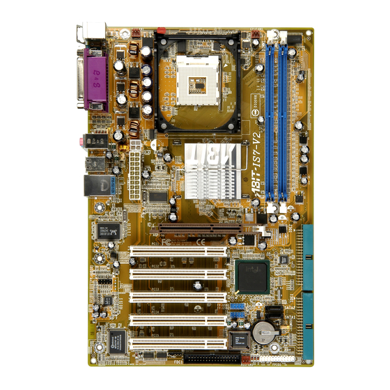
Page 21: Layout Diagram
Introduction 1-2. Layout Diagram User’s Manual... - Page 22 Chapter 1 Chapter 1 IS7-V IS7-V...
-
Page 23: Chapter 2. Hardware Setup
Hardware Setup Chapter 2. Hardware Setup Before the Installation: Turn off the power supply switch (fully turn off the +5V standby power), or disconnect the power cord before installing or unplugging any connectors or add-on cards. Failing to do so may cause the motherboard components or add-on cards to malfunction or damaged. 2-1. -
Page 24: Install Pentium ® 4 Cpu And Heatsink Supporting-Base
Retention Module Base. 6. The Fan and Retention Mechanism Assembly and Retention Module Base should now firmly lock up with each other with the heatsink inside. ATTENTION: Do not forget to set the correct bus frequency and multiple for your processor. IS7-V... -
Page 25: Install System Memory
Hardware Setup 2-3. Install System Memory This motherboard provides 2 184-pin DDR DIMM sites for memory expansion available from minimum 128MB to maximum 2GB. Table 2-1. Valid Memory Configurations Bank Memory Module Total Memory Bank 0, 1 (DIMM1) 128, 256, 512MB, 1GB 128MB ~ 1GB Bank 2, 3 (DIMM2) 128, 256, 512MB, 1GB... -
Page 26: Connectors, Headers And Switches
Plug in the AC power cord only after you have carefully checked everything. (1). ATX Power Input Connectors This motherboard provides two power connectors to connect to an ATX12V power supply with 300W, 20A +5VDC, and 720mA +5VSB capacity at least. IS7-V... -
Page 27: Fan Connectors
Hardware Setup (2). FAN Connectors These 3-pin connectors each provide power to the cooling fans installed in your system. The CPU must be kept cool by using a powerful fan with heatsink. The system is capable of monitoring the speed of the CPU fan. •... -
Page 28: Cmos Memory Clearing Header
Pin 1-2 shorted (default): Normal operation. • Pin 2-3 shorted: Clear CMOS memory. WARNING: Turn the power off first (including the +5V standby power) before clearing the CMOS memory. Failing to do so may cause your system to work abnormally or malfunction. IS7-V... -
Page 29: Front Panel Audio Connection Header
Hardware Setup (4). Front Panel Audio Connection Header This header provides the connection to audio connector at front panel. • To use the audio connector at front panel, remove all the jumpers on this header, and then connect to front panel by the extension cable provided with the chassis. •... -
Page 30: Front Panel Switches & Indicators Headers
Connects to the Suspend LED cable (if there is one) of chassis front panel. • PWR-ON (Pin 6, 8): Connects to the Power Switch cable of chassis front panel. • PLED (Pin 16, 18, 20): Connects to the Power LED cable of chassis front panel. IS7-V... -
Page 31: Additional Usb Port Headers
Hardware Setup (6). Additional USB Port Headers These headers each provide 2 additional USB 2.0 ports connection through an USB cable designed for USB 2.0 specifications. Pin Assignment Pin Assignment Data0 - Data1 - Data0 + Data1 + Ground Ground User’s Manual... -
Page 32: System Management Bus Headers
If more than one master simultaneously tries to control the bus, an arbitration procedure decides which master gets priority. (8). Internal Audio Connectors These connectors connect to the audio output of internal CD-ROM drive or add-on card. IS7-V... -
Page 33: Accelerated Graphics Port Slot
Hardware Setup 2-11 (9). Accelerated Graphics Port Slot This slot supports an optional AGP graphics card up to AGP 8X mode. Please refer to our Web site for more information on graphics cards. ATTENTION: This motherboard does not support 3.3V AGP cards. Use only 1.5V or 0.8V AGP cards. User’s Manual... -
Page 34: Floppy Disk Drive Connector
2. Install the other end(s) of ribbon cable into the disk drive connector(s). The colored edge of the ribbon cable should be also aligned with pin-1 of disk drive connector. The endmost connector should be attached to the drive designated as Drive A. IS7-V... -
Page 35: Ide Connectors
Hardware Setup 2-13 (11). IDE Connectors This motherboard provides two IDE ports to connect up to four IDE drives at Ultra ATA/100 mode by Ultra ATA/66 ribbon cables. Each cable has 40-pin 80-conductor and three connectors, providing two hard drives connection with motherboard. Connect the single end (blue connector) at the longer length of ribbon cable to the IDE port on motherboard, and the other two ends (gray and black connector) at the shorter length of the ribbon cable to the connectors on hard drives. -
Page 36: Serial Ata Connectors
These connectors are provided to attach one Serial ATA device at each channel via Serial ATA cable. For more information on how to configure the function mode for SATA1 and SATA2, please refer to the item “Serial ATA 1 Mode” and “Serial ATA 2 Mode” in the BIOS menu of “OnChip IDE Device”. IS7-V... -
Page 37: Back Panel Connectors
Hardware Setup 2-15 (13). Back Panel Connectors • Mouse: Connects to PS/2 mouse. • Keyboard: Connects to PS/2 keyboard. • LPT1: Connects to printer or other devices that support this communication protocol. • COM1: Connects to external modem, mouse or other devices that support this communication protocol. - Page 38 2-16 2-16 Chapter 2 Chapter 2 IS7-V IS7-V...
-
Page 39: Chapter 3. Bios Setup
BIOS Setup Chapter 3. BIOS Setup This motherboard provides a programmable EEPROM that you can update the BIOS utility. The BIOS (Basic Input/Output System) is a program that deals with the basic level of communication between processor and peripherals. Use the BIOS Setup program only when installing motherboard, reconfiguring system, or prompted to “Run Setup”. -
Page 40: Softmenu Setup
Chapter 3 3-1. SoftMenu Setup The SoftMenu utility is ABIT’s exclusive and ultimate solution in programming the CPU operating speed. All the parameters regarding CPU FSB speed, multiplier factor, the AGP & PCI clock, and even the CPU core voltage are all available at your fingertips. - Page 41 BIOS Setup Multiplier Factor: This item selects the multiplier factors for your CPU if it is not locked. Estimated new CPU clock: This item displays the frequency sum up from the previous item [Ext. Clock] and [Multiplier Factor]. N/B Strap CPU As: This item sets the external hardware reset strap assigned to MCH (Memory Controller Hub).
-
Page 42: Standard Cmos Features
3 Master, IDE Channel 4 Master: Click <Enter> key to enter its submenu: NOTE: Item “IDE Channel 3 Master” and “IDE Channel 4 Master” appears only when the item “OnChip Serial ATA” in the “OnChip IDE Device” menu is set as [Enhanced Mode]. IS7-V... - Page 43 BIOS Setup IDE HDD Auto-Detection: This item allows you to detect the parameters of IDE drives by pressing <Enter> key. The parameters will be shown on the screen automatically. IDE Channel 1 Master/Slave, IDE Channel 2 Master/Slave, Extended IDE Drive: When set to [Auto], the BIOS will automatically check what kind of IDE drive you are using.
- Page 44 640K for system with 640K or more memory size installed on the motherboard. Extended Memory: This item displays the amount of extended memory detected during system boot-up. Total Memory: This item displays the total memory available in the system. IS7-V...
-
Page 45: Advanced Bios Features
BIOS Setup 3-3. Advanced BIOS Features Hyper-Threading Technology This option enables or disables the processor’s Hyper-Threading Technology Leave this item to its default setting to enable the simultaneous multi-threaded (SMT) processor so as to make one physical processor looks like two logical processors to the OS and applications. This option is for CPU with Hyper-Threading Technology only. - Page 46 Intel OnScreen Branding: This item determines whether to display the “Intel Inside” logo or not at system boots up. Disable Unused PCI Clock: This option disables the clock of PCI slot that is not in use. IS7-V...
- Page 47 BIOS Setup [Yes]: The system automatically detect the unused DIMM and PCI slots, and stop sending clock signal to these unused PCI slots. [No]: The system always send clock signal to all PCI slots. NOTE: Set this option to [No] setting if there are adapters that cannot be automatically detected by the system and will cause malfunction.
-
Page 48: Advanced Chipset Features
As with caching the system BIOS, enabling the Video BIOS cache will allow access to video BIOS addressed at C0000H to C7FFFH to be cached, if the cache controller is also enabled. The larger the range of the Cache RAM, the faster the video performance will be. IS7-V... - Page 49 BIOS Setup 3-11 Memory Hole At 15M-16M: When set to [Enabled], the memory address space at 15M-16M will be reserved for ISA expansion cards that specifically requires this setting. This makes the memory from 15MB and up unavailable to the system.
-
Page 50: Integrated Peripherals
This item allows you to set the Ultra DMA in use. [Auto]: The BIOS will select the best available option after checking your hard drive or CD-ROM. [Disabled]: The BIOS will not detect these categories. If problem arises in using Ultra DMA devices, try disabling this item. IS7-V... - Page 51 BIOS Setup 3-13 OnChip IDE-2 Controller: The description is same as the OnChip IDE-1 Controller. OnChip Serial ATA: This item determines the function for on-chip Serial ATA. [Disabled]: Disable the Serial ATA controller. [Auto]: Allows the Serial ATA controller to be arranged by BIOS automatically. [Combined Mode]: Parallel ATA and Serial ATA are combined together.
-
Page 52: Superio Device
This item allows you to select [BIOS] for using USB mouse in DOS environment, or [OS] in OS environment. OnChip Audio Controller: This option enables or disables the audio controller. SuperIO Device: Click <Enter> key to enter its submenu: IS7-V... - Page 53 BIOS Setup 3-15 Onboard FDC Controller: This option enables or disables the onboard FDC controller. Onboard Serial Port: This item determines which I/O addresses the onboard Serial Port controller will access. [Auto]: The system automatically select an I/O address for the onboard Serial Port. [3F8/IRQ4, 2F8/IRQ3, 3E8/IRQ4, 2E8/IRQ3]: Allows you to manually select an I/O address for the onboard Serial Port.
-
Page 54: Onboard Pci Device
This item allows you to use the boot ROM (instead of a disk drive) to boot-up the system and access the local area network directly. Enhance Performance: This option enhances the LAN performance by making it as the first priority among the PCI devices. IS7-V... -
Page 55: Power Management Setup
BIOS Setup 3-17 3-6. Power Management Setup ACPI Suspend Type: This item selects the type of Suspend mode. [S1(Power On Suspend)]: Enables the Power On Suspend function. [S3(Suspend To RAM)]: Enables the Suspend to RAM function. Resume by USB From S3: When set to [Enabled], this item allows you to use a USB device to wake up a system that is in the S3 (STR - Suspend To RAM) state. - Page 56 If the system’s power is off when AC power failure occurs, it will remain off when power returns. If the system’s power is on when AC power failure occurs, the system will power-on when power returns. IS7-V...
-
Page 57: Pnp/Pci Configurations
BIOS Setup 3-19 3-7. PnP/PCI Configurations Resources Controlled By: This item configures all of the boot and Plug-and-Play compatible devices. [Auto]: The system will automatically detect the settings. [Manual]: Choose the specific IRQ resources in the “IRQ Resources” menu. IRQ Resources: Click <Enter>... - Page 58 PIRQ_4 Assignment INT A INT D INT C INT B PIRQ_5 Assignment INT B INT A INT D INT C PIRQ_6 Assignment INT C INT B INT A INT D PIRQ_7 Assignment INT D INT C INT B INT A IS7-V...
-
Page 59: Pc Health Status
BIOS Setup 3-21 3-8. PC Health Status FAN Fail Alarm Selectable: This item selects the fan that will be monitored for malfunction. Shutdown When CPUFAN Fail: When set to [Enabled], the system will be shut down if the CPU fan is not running. Shutdown Temperature: This item sets the temperature that would shutdown the system automatically in order to prevent system overheats. -
Page 60: Load Fail-Safe Defaults
This option protects the BIOS configuration or restricts access to the computer itself. 3-12. Save & Exit Setup This option saves your selections and exits the BIOS setup menu. 3-13. Exit Without Saving This option exits the BIOS setup menu without saving any change. IS7-V... -
Page 61: Appendix A. Install Intel Chipset Software Utility
Install Intel Chipset Software Utility Appendix A. Install Intel Chipset Software Utility NOTE: Please install this Intel Chipset driver first after having installed the Windows operating system. The installation procedures and screen shots in this section are based on Windows XP operating system. - Page 62 Appendix A Appendix A IS7-V IS7-V...
-
Page 63: Appendix B. Install Audio Driver
Install Audio Driver Appendix B. Install Audio Driver The installation procedures and screen shots in this section are based on Windows XP operating system. For those of other OS, please follow its on-screen instruction. Insert the Driver & Utility CD into CD-ROM drive, it should execute the installation program automatically. - Page 64 Appendix B Appendix B IS7-V IS7-V...
-
Page 65: Appendix C. Install Lan Driver
Install LAN Driver Appendix C. Install LAN Driver The installation procedures and screen shots in this section are based on Windows XP operating system. For those of other OS, please follow its on-screen instruction. Insert the Driver & Utility CD into CD-ROM drive, it should execute the installation program automatically. - Page 66 Appendix C IS7-V...
-
Page 67: Appendix D. Install Usb 2.0 Driver
Install USB 2.0 Driver Appendix D. Install USB 2.0 Driver NOTE: The “USB 2.0 Driver” packed in the “Driver & Utility CD” is currently available for Windows 9x and ME only. To install this driver for Windows XP or Windows 2000, you have to download their latest service pack first from Microsoft’s web site. - Page 68 Appendix D Appendix D IS7-V IS7-V...
-
Page 69: Appendix E. Bios Update Guide
BIOS Update Guide Appendix E. BIOS Update Guide The procedure illustrated here is based on the model SE6 as an example; all other models follow the same process. 1. First, find out the model name and version number of this motherboard. You can find a bar-code sticker typed with model name and version number on motherboard PCB. - Page 70 If this “BIOS boot block” remains intact when the BIOS becomes corrupt during programming, then you can boot from a bootable floppy next time you boot your computer. This allows you to flash your BIOS again without the need for technical support from the dealer. IS7-V...
-
Page 71: Appendix F. Hardware Monitoring (The Winbond Hardware Doctor Utility
Hardware Monitoring (The Winbond Hardware Doctor Utility) Appendix F. Hardware Monitoring (The Winbond Hardware Doctor Utility) The Winbond Hardware Doctor is a self-diagnostic system for PCs used with Winbond W83627HF chipset. It protects PC hardware by monitoring several critical items including power supply voltages, CPU &... - Page 72 Winbond hardware doctor on-line help. It should give you enough information to answer your questions. 7. This screen appears. Hardware Doctor shows you the status of Voltage, Fan Speed, and Temperature readings as well. If any reading is IS7-V...
-
Page 73: Appendix G. Troubleshooting (Need Assistance
Troubleshooting (Need Assistance?) Appendix G. Troubleshooting (Need Assistance?) Q & A: Q: Do I need to clear the CMOS before I use a new motherboard to assemble my new computer system? A: Yes, we highly recommend that you clear the CMOS before installing a new motherboard. Please move the CMOS jumper from its default 1-2 position to 2-3 for a few seconds, and then back. - Page 74 Sound Card Driver. Write down the Sound Card model, motherboard model, BIOS identification number on the technical support file (refer to main instructions), and describe the problem in the space provided. We will show you how to fill the “Technical Support Form”. IS7-V...
- Page 75 To fill in this “Technical Support Form”, refer to the step-by-step instructions given below: . MODEL: Note the model number given in your user’s manual. Example: IS7-V . Motherboard model number (REV): Note the motherboard model number labeled on the motherboard as “REV:*.**”.
-
Page 76: Technical Support Form
Appendix G Technical Support Form Company Name: Phone Number: Contact Person: Fax Number: E-mail Address: Model BIOS ID # Motherboard Model No. DRIVER REV OS/Application Hardware Name Brand Specifications IDE1 IDE2 IDE1 CD-ROM-Drive IDE2 System Memory ADD-ON CARD Problem Description: IS7-V... -
Page 77: Appendix H. How To Get Technical Support
Also please make sure you have the latest drivers from your peripheral cards makers! 3. Check the ABIT Technical Terms Guide and FAQ on our Website. We are trying to expand and make the FAQs more helpful and information rich. Let us know if you have any suggestions. - Page 78 They should have reasonable return or refund policies. How they serve you is also a good reference for your next purchase. 6. Contacting ABIT. If you feel that you need to contact ABIT directly you can send email to the ABIT technical support department. First, please contact the support team for the branch office closest to you.
- Page 79 How to Get Technical Support North America and South America: Japan: ABIT Computer (U.S.A.) Corporation ABIT Computer (Japan) Co. Ltd. 45531 Northport Loop West, Fax: 81-3-5396-5110 Fremont, California 94538, U.S.A. http://www.abit4u.jp Tel: 1-510-623-0500 Fax: 1-510-623-1092 Shanghai: sales@abit-usa.com ABIT Computer (Shanghai) Co. Ltd.
- Page 80 Please contact the reseller from whom you bought the product. You should be able to get RMA service there. 8. Reporting Compatibility Problems to ABIT. Because of tremendous number of email messages we receive every day, we are forced to give greater weight to certain types of messages than to others.
Need help?
Do you have a question about the IS7-V and is the answer not in the manual?
Questions and answers