Table of Contents
Advertisement
Advertisement
Table of Contents

Subscribe to Our Youtube Channel
Related Manuals for Abit I-45C


Summary of Contents for Abit I-45C
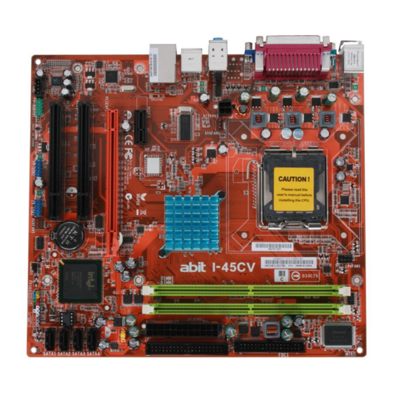
- Page 1 I-45C I-45CV Motherboard Intel Socket 775 Installation Guide...
- Page 2 If you do not properly set the motherboard settings, causing the motherboard to malfunction or fail, we cannot guarantee any responsibility. For EU-member States: Directive 2002/96/EC on Waste Electrical and Electronic Equipment (WEEE): The use of the symbol indicates that this product may not be treated as household waste.
- Page 3 信息产品环保使用期限通则>制 定的,适用于中国境内销售的电子 信息产品的标识。 只要按照安全及使用说明内容在 正常使用电子信息产品情况下、从 生产月期算起,在此期限内产品中 含有的有毒有害物质不致发生外 泄或突变、不致对环境造成严重污 染或对其人身、财产造成严重损害。产品正常使用后,要废弃在环保使用 年限内或者刚到年限的产品,请根据国家标准采取适当的方法进行处置。 另外,此期限不同于质量/功能的保证期限。 The Mark and Information are applicable for People's Republic of China only. I-45C/I-45CV 有毒有害物质含有表 产品中有毒有害物质或元素的名称及含量 有毒有害物质或元素 部件名称 铅(Pb) 汞(Hg) 镉(Cd) PCB 板 ○ ○ ○ 结构件 ○ ○ ○...
-
Page 4: Table Of Contents
1.9 Connecting Rear Panel I/O Devices... 12 2. BIOS Setup ... 13 3. Driver & Utility ... 14 4. Appendix ... 15 4.1 規格(繁體中文)...15 4.2 规格(简体中文)...16 4.3 Troubleshooting (How to Get Technical Support?) ...17 4.3.1 Q & A...17 4.3.2 Technical Support Form...18 4.4 Contact Information...19 I-45C/I-45CV... -
Page 5: Hardware Setup
Due to the chipset limitation, the DDR2 533 memory module runs at 500MHz with FSB1333 CPU. Graphics • Integrated Intel Graphics Media Accelerator 950 (GMA950) • I-45C: Onboard GbE LAN • I-45CV: Onboard 10/100 LAN Audio • Onboard HD 5.1 Channel Audio CODEC... -
Page 6: Choosing A Computer Chassis
Plug in the AC power cord only after you have carefully checked everything. To install this motherboard: 1. Locate all the screw holes on the motherboard and the chassis base. 2. Place all the studs or spacers needed on the chassis base and have them tightened. -
Page 7: Checking Jumper Settings
CPU or memory modules. This header uses a jumper cap to clear the CMOS memory and have it reconfigured to the default values stored in BIOS. I-45C/I-45CV OPEN • Pin-1 and pin-2 shorted (Default): Normal operation. -
Page 8: Connecting Chassis Components
20-pin power supply may cause the system unstable or even unbootable for the sake of insufficient electricity. A minimum power of 300W or higher is recommended. ATX 12V 4-Pin Power Connector: This connector supplies power to CPU. The system will not start without connecting power to this one. I-45C/I-45CV... -
Page 9: Front Panel Switches And Indicators Headers
Connects to the Suspend LED cable (if there is one) of chassis front panel. • PWR (Pin 6, 8): Connects to the Power Switch cable of chassis front panel. I-45C/I-45CV • PLED (Pin 16, 18, 20): Connects to the Power LED cable of chassis front panel. 1.5.3 FAN Power Connectors These connectors each provide power to the cooling fans installed in your system. -
Page 10: Installing Hardware
1.6 Installing Hardware DO NOT scratch the motherboard when installing hardware. An ※ accidental scratch of a tiny surface-mount component may seriously damage the motherboard. In order to protect the contact pins, please pay attention to these ※ notices: 1. A maximum 20 cycles of CPU installation is recommended. - Page 11 7. Secure the lever with the hook under retention tab. I-45C/I-45CV 8. Place the heatsink and fan assembly onto the socket. Align the four fasteners toward the four mounting holes on the motherboard.
-
Page 12: Ddr2 Memory Slots
DIMM module. Static electricity can damage the electronic components of the ※ computer or optional boards. Before starting these procedures, ensure that you are discharged of static electricity by touching a grounded metal object briefly. I-45C/I-45CV... -
Page 13: Connecting Peripheral Devices
2. Attach the SATA power cable to the SATA device and connect the other end from the power supply. The motherboard in this photo is served for DEMO only, and may not ※ be the same type or model as the one described in this manual. -
Page 14: Additional Usb 2.0 Port Headers
Data0 + Ground Make sure the connecting cable bears the same pin assignment. ※ 1.7.4 Internal Audio Connectors This connector connects to the audio output of internal CD-ROM drive or add-on card. Pin Assignment Data1 - Data1 + Ground I-45C/I-45CV... -
Page 15: Front Panel Audio Connection Header
AVCC FRO-R MIC2_JD F_IO_SEN FRO-L LINE2_JD I-45C/I-45CV ※ Driver Configuration for AC’97 audio connection: The audio driver is originally configured to support HD Audio. For AC’97 audio connection, you may: 1. Right-click the “Realtek HD 2. Click “Audio I/O” tab, and Pin Assignment (AC’97 AUDIO) -
Page 16: Pci And Pci Express X16, X1 Slots
Install PCI Express X1 cards into slot “PCIE1”. Install PCI cards into slots “PCI1” and/or “PCI2”. 1.9 Connecting Rear Panel I/O Devices The rear I/O part of this motherboard provides the following I/O ports: • Mouse: Connects to PS/2 mouse. -
Page 17: Bios Setup
2. BIOS Setup This motherboard provides a programmable EEPROM so that you can update the BIOS utility. The BIOS (Basic Input/Output System) is a program that deals with the basic level of communication between processor and peripherals. Use the BIOS Setup program only when installing motherboard, reconfiguring system, or prompted to “Run... -
Page 18: Driver & Utility
[Manual]: Click this button to enter the user’s manual menu. • [Utility]: Click this button to enter the utilities installation menu. • [abit Utility]: Click to enter the installation menu of utilities exclusively developed by ABIT. • [Browse CD]: Click this button to browse the contents of this “Driver &... -
Page 19: Appendix
因為晶片組的限制, DDR2 533 記憶模組在 FSB1333 的 CPU 之下的速度 只有 500MHz。 圖形埠 • 整合 Intel Graphics Media Accelerator 950 (GMA950) 網路 • I-45C: 內建 GbE LAN • I-45CV: 內建 10/100 LAN 音效 • 內建 5.1 聲道 HD 音效 I-45C/I-45CV Serial ATA •... -
Page 20: 规格(简体中文
因为芯片组的限制, DDR2 533 内存模组在 FSB1333 的 CPU 之下的速度 只有 500MHz。 图形端口 • 整合 Intel Graphics Media Accelerator 950 (GMA950) 网络 • I-45C: 内建 GbE LAN • I-45CV: 内建 10/100M LAN 音效 • 支持 5.1 声道 HD 音效 串行 ATA • 4 个 SATA 3.0Gb/s 扩充插槽... -
Page 21: Troubleshooting (How To Get Technical Support?)
4.3 Troubleshooting (How to Get Technical Support?) 4.3.1 Q & A Do I need to clear the CMOS before I use a new motherboard to assemble my new computer system? Yes, we highly recommend that you clear the CMOS before installing a new motherboard. -
Page 22: Technical Support Form
See the blank Technical Support Form, or visit our website to fill in the form on line (http://www.abit.com.tw/page/en/contact/technical.php). Is the motherboard dead? Do I need to return it to where I bought from or go through an RMA process? After you have gone through the troubleshooting procedures, yet the problem still exists, or you find an evident damage on the motherboard, please contact our RMA center. -
Page 23: Contact Information
Website: http://www.abit-usa.com Latin America: r aymond@abit-usa.com RMA Center: http://rma.abit-usa.com UK, Ireland Universal ABIT UK Co. Ltd. Unit 3, 24-26 Boulton Road, Stevenage, Herts SG1 4QX, United Kingdom Tel: +44-1438-228888 Fax: +44-1438-226333 For technical support and RMA return: Tel: +44-1438-362088 technical@abitcomputer.co.uk returns@abitcomputer.co.uk... - Page 24 P/N: 4310-0000-96 Rev. 1.00...
Need help?
Do you have a question about the I-45C and is the answer not in the manual?
Questions and answers