
Related Manuals for Abit IB9


Summary of Contents for Abit IB9
- Page 1 Motherboard Socket 775 Intel Core 2 Duo, Pentium Extreme Editon, Pentium D, Pentium 4 Intel P965 / ICH8 FSB1066 Dual DDR2 800 PCI Express Gigabit LAN 4x SATA 3Gb/s 7.1 Channel HD Audio...
- Page 2 No part of this manual may be reproduced, transmitted or transcribed without the expressed written permission of the manufacturer and authors of this manual. If you do not properly set the motherboard settings, causing the motherboard to malfunction or fail, we cannot guarantee any responsibility.
-
Page 3: Table Of Contents
1. Hardware Setup ... 1-1 1.1 Specifications ...1-1 1.2 Motherboard Layout...1-2 1.3 Choosing a Computer Chassis ...1-3 1.4 Installing Motherboard ...1-3 1.5 Checking Jumper Settings ...1-4 1.5.1 CMOS Memory Clearing Header and Backup Battery ...1-4 1.5.2 Wake-up Header ...1-6 1.6 Connecting Chassis Components...1-7 1.6.1 ATX Power Connectors ...1-7... - Page 4 3.3 LAN Driver ...3-2 3.4 iTE IDE Controller Driver ...3-3 3.5 USB 2.0 Driver...3-3 3.6 ABIT EQ (The Hardware Doctor Utility)...3-4 3.7 FlashMenu (BIOS Update Utility) ...3-5 3.8 Build A Driver Disk Under Windows Environment...3-6 3.9 Build A Driver Disk Under DOS Environment ...3-7 4.
-
Page 5: Hardware Setup
• 1x S/PDIF Out • 1x 7.1CH Audio Connector • 4x USB 2.0 connectors • 1x RJ-45 Gigabit LAN connector ABIT Engineered ™ • ABIT SoftMenu Technology RoHS • 100% Lead-free process and RoHS compliant Miscellaneous • ATX form factor (305mm x 245mm) -
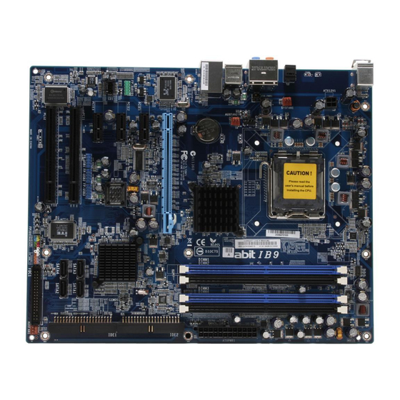
Page 6: Motherboard Layout
1.2 Motherboard Layout... -
Page 7: Choosing A Computer Chassis
Most chassis have alternatives for I/O shield located at the rear panel. Make sure the I/O shield of the chassis matches the I/O port configuration of this motherboard. You can find an I/O shield specifically designed for this motherboard in its package. -
Page 8: Checking Jumper Settings
1.5 Checking Jumper Settings • For a 2-pin jumper, plug the jumper cap on both pins will make it CLOSE (SHORT). Remove the jumper cap, or plug it on either pin (reserved for future use) will leave it at OPEN position. •... - Page 9 CMOS Backup Battery: An onboard battery saves the CMOS memory to keep the BIOS information stays on even after disconnected your system with power source. Nevertheless, this backup battery exhausts after some five years. Once the error message like “CMOS BATTERY HAS FAILED” or “CMOS checksum error”...
-
Page 10: Wake-Up Header
1.5.2 Wake-up Header These headers use a jumper cap to enable/disable the wake-up function. • USB-PWR1: Pin 1-2 shorted (Default): Disable wake-up function support at USB1 port. Pin 2-3 shorted: Enable wake-up function support at USB1 port. • USB-PWR2: Pin 1-2 shorted (Default): Disable wake-up function support at USB2 port. Pin 2-3 shorted: Enable wake-up function support at USB2 port... -
Page 11: Connecting Chassis Components
1.6 Connecting Chassis Components 1.6.1 ATX Power Connectors These connectors provide the connection from an ATX power supply. As the plugs from the power supply fit in only one orientation, find the correct one and push firmly down into these connectors. -
Page 12: Front Panel Switches & Indicators Headers
1.6.2 Front Panel Switches & Indicators Headers This header is used for connecting switches and LED indicators on the chassis front panel. Watch the power LED pin position and orientation. The mark “+” align to the pin in the figure below stands for positive polarity for the LED connection. -
Page 13: Fan Power Connectors
1.6.3 FAN Power Connectors These connectors each provide power to the cooling fans installed in your system. • CPUFAN1: CPU Fan Power Connector • SYSFAN1: System Fan Power Connector • AUXFAN1~2: Auxiliary Fan Power Connector ※ These fan connectors are not jumpers. DO NOT place jumper caps on these connectors. -
Page 14: Installing Hardware
1.7 Installing Hardware ※ DO NOT scratch the motherboard when installing hardware. An accidentally scratch of a tiny surface-mount component may seriously damage the motherboard. ※ In order to protect the contact pins, please pay attention to these notices: 1. A maximum 20 cycles of CPU installation is recommended. - Page 15 8. Place the heatsink and fan assembly onto the socket. Align the four fasteners toward the four mounting holes on the motherboard. 9. Press each of the four fasteners down into the mounting holes. Rotate the fastener clock-wise to lock the heatsink and fan assembly into position.
-
Page 16: Ddr2 Memory Slots
1.7.2 DDR2 Memory Slots • To reach the optimum performance in dual-channel configurations, install identical DDR2 DIMM pairs for each channel. • Install DIMMs with the same CAS latency. To reach the optimum compatibility, obtain memory modules from the same vendor. ※... -
Page 17: Connecting Peripheral Devices
1.8 Connecting Peripheral Devices 1.8.1 Floppy and IDE Disk Drive Connectors The FDC1 connector connects up to two floppy drives with a 34-wire, 2-connector floppy cable. Connect the single end at the longer length of ribbon cable to the FDC1 on the board, the two connectors on the other end to the floppy disk drives connector. -
Page 18: Serial Ata Connectors
Attach the SATA power cable to the SATA device and connect the other end from the power supply. ※ The motherboard in this illustration is served for DEMO only, may not be the same type or model as the one described in this user’s manual. 1-14... -
Page 19: Additional Usb 2.0 Port Headers
1.8.3 Additional USB 2.0 Port Headers Each header supports 2x additional USB 2.0 ports by connecting bracket or cable to the rear I/O panel or the front-mounted USB ports of your chassis. ※ Make sure the connecting cable bears the same pin assignment. Pin Assignment Data0 - Data0 +... -
Page 20: Internal Audio Connectors
Audio, yet for AC’97 Audio CODEC connection, you must carefully check the pin assignment before connecting from the front panel module. An incorrect connection may cause malfunction or even damage the motherboard. ※ Please do not connect the “Ground” cable or “USB VCC” cable from the front panel module to the Pin 4 “AVCC”... - Page 21 Driver Configuration for AC’97 audio connection: The audio driver is originally configured to support HD Audio. For AC’97 audio connection, you may: Right-click the “Realtek HD Audio Manager” icon system tray. Click “Audio I/O” tab, and then click “Connector Settings”. Click “Disabled front panel jack detection”, and then click “OK”...
-
Page 22: Pci And Pci Express X16, X1 Slots
1.8.6 PCI and PCI Express X16, X1 Slots Install PCI Express X16 graphics card into slot “PCIEXP1”. Install PCI Express X1 cards into slots “PCI-E1”, “PCI-E2”, and/or “PCI-E3”. Install PCI cards into slots “PCI1” and/or “PCI2”. 1-18... -
Page 23: Onboard Status Display
1.9 Onboard Status Display 1.9.1 Power Source Indicators These indicators work as a reminding device to display the power status of this motherboard with power source connected. • 5VSB: This LED lights up when the power supply is connected with power source. -
Page 24: Connecting Rear Panel I/O Devices
1.10 Connecting Rear Panel I/O Devices The rear I/O part of this motherboard provides the following I/O ports: • Mouse: Connects to PS/2 mouse. • Keyboard: Connects to PS/2 keyboard. • OPT-OUT1: This connector provides an S/PDIF-Out connection through optical fiber to digital multimedia devices. -
Page 25: Bios Setup
2. BIOS Setup This motherboard provides a programmable EEPROM so that you can update the BIOS utility. The BIOS (Basic Input/Output System) is a program that deals with the basic level of communication between processor and peripherals. Use the BIOS Setup program only when installing motherboard, reconfiguring system, or prompted to “Run Setup”. -
Page 26: Softmenu Setup
Brand Name This item displays the CPU model name installed on this motherboard. Frequency This item displays the processor speed of the CPU installed on this motherboard. Cache Size This item displays the L2 cache size of your CPU. CPU Operating Speed This item displays the CPU operating speed according to the type and speed of your CPU. - Page 27 N/B Strap CPU As This item sets the external hardware reset strap assigned to MCH (Memory Controller Hub). DRAM Spec. (CPU:DRAM) This item determines the DRAM frequency. PCI Express Frequency This item determines the PCI Express slot frequency. Voltages Control This option allows you to switch between the default and user-defined voltages.
-
Page 28: Standard Cmos Features
2.2 Standard CMOS Features Phoenix – AwardBIOS CMOS Setup Utility Date (mm:dd:yy) Time (hh:mm:ss) ► IDE Channel 1 Master ► IDE Channel 2 Master ► IDE Channel 3 Master ► IDE Channel 4 Master Drive A Drive B Floppy 3 Mode Support Halt On Base Memory Extended Memory... - Page 29 IDE HDD Auto-Detection This item allows you to detect the parameters of IDE drives by pressing <Enter> key. The parameters will be shown on the screen automatically. IDE Channel 1 Master, IDE Channel 2 Master, IDE Channel 3 Master, IDE Channel 4 Master When set to [Auto], the BIOS will automatically check what kind of SATA hard drive you are using.
- Page 30 This item displays the amount of base memory installed in the system. The value of the base memory is typically 640K for system with 640K or more memory size installed on the motherboard. Extended Memory This item displays the amount of extended memory detected during system boot-up.
-
Page 31: Advanced Bios Features
2.3 Advanced BIOS Features Phoenix – AwardBIOS CMOS Setup Utility CPU L3 Cache Hyper-Threading Technology Quick Power on Self Test ► CPU Feature ► Hard Disk Boot Priority First Boot Device Second Boot Device Third Boot Device Boot Other Device Boot Up Floppy Seek Boot Up NumLock Status Security Option... -
Page 32: Cpu Feature
CPU Feature Click <Enter> key to enter its submenu: Phoenix – AwardBIOS CMOS Setup Utility Thermal Management - TM2 Bus Ratio - TM2 Bus VID Limit CPUID MaxVal C1E Function Execute Disable Bit Virtualization Technology EIST Function :Move Enter:Select +/-/PU/PD:Value F10:Save ESC:Exit F1:General Help F5: Previous Values Thermal Management This item selects the type of thermal monitoring. - Page 33 But by doing this, you will have to reset all previously set options. MPS Version Ctrl For OS This item specifies which version of MPS (Multi-Processor Specification) this motherboard will use. Leave this item at its default setting. Report No FDD For OS When set to [Yes], this item allows you to run some older operating system without floppy disk drive.
-
Page 34: Advanced Chipset Features
[Yes]: The system automatically detect the unused DIMM and PCI slots, and stop sending clock signal to these unused PCI slots. [No]: The system always send clock signal to all PCI slots. ※ Set this option to [No] setting if there are adapters that cannot be automatically detected by the system and will cause malfunction. - Page 35 PCI Express Root Port Func Click <Enter> key to enter its submenu: Phoenix – AwardBIOS CMOS Setup Utility PCI Express Slot 1 PCI Express Slot 2 PCI Express Slot 3 PCI-E Compliancy Mode :Move Enter:Select +/-/PU/PD:Value F10:Save ESC:Exit F1:General Help F5: Previous Values PCI Express Slot 1 / PCI Express Slot 2 / PCI Express Slot 3 This option enables or disables the PCI Express port function.
-
Page 36: Integrated Peripherals
2.5 Integrated Peripherals Phoenix – AwardBIOS CMOS Setup Utility ► OnChip IDE Device ► OnChip PCI Device ► Super-IO Device ► Onboard PCI Device :Move Enter:Select +/-/PU/PD:Value F10:Save ESC:Exit F1:General Help F5: Previous Values OnChip IDE Device Click <Enter> key to enter its submenu: Phoenix –... - Page 37 OnChip PCI Device Click <Enter> key to enter its submenu: Phoenix – AwardBIOS CMOS Setup Utility OnChip USB Controller - USB 2.0 Controller - USB Keyboard Support - USB Mouse Support OnChip Audio Controller :Move Enter:Select +/-/PU/PD:Value F10:Save ESC:Exit F1:General Help F5: Previous Values OnChip USB Controller This option enables or disables the USB controller.
-
Page 38: Onboard Pci Device
Super-IO Device Click <Enter> key to enter its submenu: Phoenix – AwardBIOS CMOS Setup Utility Floppy Disk Controller :Move Enter:Select +/-/PU/PD:Value F10:Save ESC:Exit F1:General Help F5: Previous Values Floppy Disk Controller This option enables or disables the floppy disk controller. Onboard PCI Device Click <Enter>... -
Page 39: Power Management Setup
2.6 Power Management Setup Phoenix – AwardBIOS CMOS Setup Utility ACPI Suspend Type - Resume by USB from S3 Power Button Function CPU THRM-Throttling Wake-Up by PME# of PCI Wake-Up by Onboard LAN Wake-Up by Alarm X - Date(of month) Alarm X - Time(hh:mm:ss) Alarm POWER On Function X - KB Power On Password... - Page 40 Date (of Month) Alarm [0]: This option power-on the system everyday according to the time set in the “Time (hh:mm:ss) Alarm” item. [1-31]: This option selects a date you would like the system to power-on. The system will power-on on the date set, and the time set in the “Time (hh:mm:ss) Alarm” item. Time (hh:mm:ss) Alarm This item sets the time you would like the system to power-on.
-
Page 41: Pnp/Pci Configurations
2.7 PnP/PCI Configurations Phoenix – AwardBIOS CMOS Setup Utility Resources Controlled By X - IRQ Resources PCI/VGA Pallete Snoop :Move Enter:Select +/-/PU/PD:Value F10:Save ESC:Exit F1:General Help F5: Previous Values Resources Controlled By This item configures all of the boot and Plug-and-Play compatible devices. [Auto]: The system will automatically detect the settings. -
Page 42: Pc Health Status
2.8 PC Health Status Phoenix – AwardBIOS CMOS Setup Utility ► ABIT FanEQ Control FAN Fail Alarm Selectable Shutdown When FAN Fail CPU Shutdown Temperature CPU Warning Temperature CPU Temperature SYS Temperature PWM Temperature CPU FAN Speed SYS FAN Speed... - Page 43 FanEQ Start Control This item sets the speed ratio for the 3-pin CPU fan assembly connected at “CPUFAN1” fan power connector to start running. FanEQ Stop Control This item sets the lowest speed ratio for the 3-pin CPU fan assembly connected at “CPUFAN1” fan power connector to run at when the CPU temperature detected is lower than the value of item “FanEQ Target Temp.”...
-
Page 44: Load Fail-Safe Defaults
2.9 Load Fail-Safe Defaults This option loads the BIOS default values for the most stable, minimal-performance system operations. 2.10 Load Optimized Defaults This option loads the BIOS default values that are factory settings for optimal-performance system operations. 2.11 Set Password This option protects the BIOS configuration or restricts access to the computer itself. -
Page 45: Driver & Utility
[Manual]: Click to enter the user’s manual menu. • [Utility]: Click to enter the utilities installation menu. • [ABIT Utility]: Click to enter the installation menu of utilities exclusively developed by ABIT. • Browse CD]: Click to browse the contents of this “Driver-&-Utility CD”. -
Page 46: Intel Chipset Software Installation Utility
3.1 Intel Chipset Software Installation Utility To install this driver: Click on the [Drivers] tab in the installation menu screen. Click the [Intel Chipset Software Installation Utility] item. The installation screen appears. Follow the prompts on the screen to complete installation. 3.2 Audio Driver To install this driver: Click on the [Drivers] tab in the... -
Page 47: Ite Ide Controller Driver
3.4 iTE IDE Controller Driver This driver is used to enable the IDE controller after having installed the Windows operating system to the hard disk connected between “IDE1” and “IDE2” connectors. To install this driver: Click on the [Drivers] tab in the installation menu screen. -
Page 48: Abit Eq (The Hardware Doctor Utility)
3.6 ABIT EQ (The Hardware Doctor Utility) The ABIT EQ is a self-diagnostic system that protects PC Hardware by monitoring critical items of Power Supply Voltage, CPU & System Fans Speed, and CPU & System Temperature. To install this utility: Click on the [ABIT Utility] tab in the installation menu screen. -
Page 49: Flashmenu (Bios Update Utility)
3.7 FlashMenu (BIOS Update Utility) The FlashMenu is a utility to flash the BIOS in a more easily and quickly way. To install this utility: Click on the [ABIT Utility] tab in the installation menu screen. Click the [FlashMenu] item. The following screen appears. -
Page 50: Build A Driver Disk Under Windows Environment
This utility is used to build the driver program for IDE controller into a floppy disk under Windows environment. ※ Connect a 3.5” floppy disk drive to the “FDC1” connector on this motherboard before entering Windows operating system. To create a driver disk: Click on the [Utility] tab in the installation menu screen. -
Page 51: Build A Driver Disk Under Dos Environment
Enter and select the BIOS menu “Advanced BIOS Features”. Configure the option “First Boot Device” to “CD-ROM” by accessing the BIOS menu “Save & Exit Setup”. Restart the system. The system will now boot from CD, and enter the ABIT Boot Manager, the following options appear (0) Boot From First HDD... - Page 52 To install OS from IDE CD-ROM: Prepare a 3.5” floppy disk drive and connect it to “FDC1” connector on this motherboard. Start install operating system. Insert this IDE driver disk into floppy disk drive when the screen instruction prompts you to install a third-party SCSI or RAID driver.
-
Page 53: Multilingual Quick Installation Guide
Ce “Guide d’Installation rapide ” contient seulement l information de base dont vous pouvez avoir besoin lors de l’installation de votre carte mère abit. Pour des opérations plus avancées, vous devez vous reporter à la version complète. Précautions d’installation du matériel •... - Page 54 une connexion supplémentaire au port IEEE1394 disponible via un câble d’extension avec une attache de fixation. Affectation TPA0 + Mise à la terre TPB0 + +12V Socle de Connections Audio sur le Panneau Avant: [FP-AUDIO1] Ce socle de connexion fournit la connexion sur panneau frontal pour l'Audio HD (Haute Définition), néanmoins pour la connexion CODEC...
-
Page 55: German//Kurze Installationsanleitung
• Erden Sie sich ordnungsgemäß, indem Sie ein statisches Handgelenksband tragen, bevor Sie das Motherboard aus seinem antistatischen Beutel herausnehmen. • Halten Sie das Motherboard an seinen Rändern fest. Kommen Sie nicht mit den darauf befindlichen Komponenten in Kontakt. • Berühren Sie keine Modulkontakte und IC-Chips. - Page 56 Polzuweisung prüfen, bevor Sie die Verbindung mit dem Frontblenden-Modul vornehmen. Eine falsche Verbindung kann eine Funktionsstörung verursachen oder sogar das Motherboard beschädigen. Bitte verbinden Sie das “Ground”-Kabel oder “USB VCC”-Kabel vom Frontblenden-Modul nicht mit dem Pol 4 “AVCC” dieses Sockels.
-
Page 57: Italian//Guida All'installazione Rapida
4.3 Italian//Guida all’installazione rapida Questa “Guida all’installazione rapida” contiene solamente le informazioni di base sull’hardware necessarie all’installazione della scheda madre abit. Fare riferimento alla versione completa della guida per eseguire le operazioni avanzate. Precauzioni sull’installazione dell’hardware • Spegnere sempre l’unità e scollegare il cavo d’alimentazione dalla presa CA prima di installare la... - Page 58 Collettore di collegamento audio del pannello frontale: [FP-AUDIO1] Questo collettore fornisce la connessione del pannello frontale per l’Audio HD (High Definition) (Alta Definizione), tuttavia per la connessione CODEC dell’Audio AC’97, bisogna controllare attentamente l’assegnazione delle spine prima di collegarlo dal modulo del pannello frontale.
-
Page 59: Spanish//Guía Rápida De Instalación
Esta “Guía de instalación rápida” contiene solamente la información básica sobre el hardware que puede necesitar durante la instalación de la placa base abit. Para conocer el funcionamiento avanzado, es necesario consultar la versión completa. Precauciones durante la configuración del hardware •... - Page 60 Terminal de puerto USB adicional: [FP-USB1], [FP-USB2] Además de las conexiones USB de la placa situadas en el panel I/O, estos terminales proporcionan cada uno dos conexiones de puerto USB disponibles mediante un cable de extensión con un soporte. Asignación Negative Data Channel 0 Positive Data...
-
Page 61: Portuguese//Guia De Instalação Rápida
Este “Guia de instalação rápida” contém apenas informação essencial sobre o hardware e necessária à instalação da sua placa principal abit. Para mais informações, terá de consultar a versão integral deste guia. Normas de segurança a ter em conta durante a montagem do hardware •... - Page 62 Atribuição TPA0 + Terra TPB0 + +12V Suporte da ligação áudio do painel frontal: [FP-AUDIO1] Este conector permite-lhe ligar o áudio de alta definição (HD) (High Definition) através do painel frontal, no entanto para ligação do CODEC de áudio AC’97 tem de verificar cuidadosamente a distribuição dos pinos antes de fazer a ligação a partir do módulo do painel...
-
Page 63: Russian//Краткое Руководство По Установке
4.6 Russian//Краткое руководство по установке В “Кратком руководстве по установке” содержится только основная информация о техническом обеспечении, которая вам может понадобиться при установке материнской платы abit. Описание дополнительных операций вы найдете в полной версии руководства. Предостережения по установке технического обеспечения •... - Page 64 Назначение Насадка аудио соединения на передней панели: [FP-AUDIO1] Назначение (HD AUDIO) AVCC Внутренние звуковые разъемы: [CD1], [AUX1] Установка CPU и блока теплоотвода Установка модулей памяти 4-12 Назначение Соединение устройств хранения данных Соединение дисковода гибких дисков: [FDC1] Соединение жестких дисков IDE: [IDE1], [IDE2] Назначение...
-
Page 65: Estonian//Kiirpaigaldusjuhend
4.7 Estonian//Kiirpaigaldusjuhend Käesolev “Kiirpaigaldusjuhend” sisaldab ainult abit-emaplaadi paigaldamiseks vajalikku riistvaraalast põhiteavet. Edasijõudnud kasutamiseks tuleb teil ikkagi pöörduda täisversiooni poole. Ettevaatusabinõud riistvara paigaldamisel • Enne emaplaadi paigaldamist või ümberseadistamist lülitage alati eelnevalt toide välja ning lahutage toitejuhe vooluvõrgust. • Enne plaadi antistaatilisest kotist välja võtmist maandage end korralikult antistaatilise turvarandmerihma abil. - Page 66 Täiendav USB-pordi päis: [FP-USB1], [FP-USB2] Lisaks S/V-paneelil paiknevatele süsteemsete USB-konnektoritele annavad need päised võimaluse USB-portide kaheks lisaühenduseks läbi klambriga varustatud pikenduskaabli. Otstarve negatiivne andmekanali 0 positiivne andmekanali 0 Täiendav IEEE1394 pordi päis: [FP-1394-1], [FP-1394-2] Lisaks S/V-paneelil paiknevatele süsteemsetele IEEE1394 konnektoritele annavad need päised võimaluse kumbki üheks IEEE1394 pordi lisaühenduseks läbi klambriga varustatud pikenduskaabli.
-
Page 67: Latvian//Ātrās Instalēšanas Instrukcija
4.8 Latvian//Ātrās instalēšanas instrukcija Šī “Ātrās instalēšanas instrukcija” ietver tikai pamata norādes iekārtai, kas nepieciešamas, instalējot abit mātesplati. Pilnīgākai darbībai nepieciešams iegūt instrukcijas paplašināto variantu. Piesardzības pasākumi iekārtas uzstādīšanā • Vienmēr pirms plates pievienošanas vai jebkuru uzstādījumu izmaiņām izslēdziet strāvas padevi un atvienojiet vadu no maiņstrāvas barošanas avota. - Page 68 Papildu USB porta galvene: [FP-USB1], [FP-USB2] Bez plates USB savienotājiem, kas atrodas ievadizvades panelī, šīs galvenes katra nodrošina papildu USB portu savienojumu, kas pieejams, izmantojot pagarinājuma kabeli ar atbalstu. Piešķire Negatīvo datu kanāls 0 Pozitīvo datu kanāls 0 Zemējums Papildu IEEE1394 porta galvene: [FP-1394-1], [FP-1394-2] Bez plates IEEE1394 savienotājiem, kas atrodas ievadizvades panelī, šīs galvenes katra nodrošina vienu papildu IEEE1394...
-
Page 69: Lithuanian//Trumpas Instaliavimo Vadovas
4.9 Lithuanian//Trumpas instaliavimo vadovas Šiame “Trumpame instaliavimo vadove” pateikta tik esminė informacija apie techninę įrangą, kurios jums gali prireikti instaliuojant pagrindinę plokštę abit. Papildomų operacijų aprašymą rasite pilnoje vadovo versijoje. Atsargumo priemonės instaliuojant techninę įrangą • Prieš instaliuodami plokštę ar keisdami parametrus visuomet išjunkite maitinimą... - Page 70 Papildomas USB prievado antgalis: [FP-USB1], [FP-USB2] Papildant plokštėje įmontuotas jungtis USB, esančias šalia panelio I/O, šie antgaliai ilgintuvo su laikytuvais dėka parūpina po dvi papildomas USB prievadų jungtis. Paskirtis Neigiamas duomenų kanalas Teigiamas duomenų kanalas Įžeminimas Papildomas IEEE1394 prievado antgalis: [FP-1394-1], [FP-1394-2] Papildant plokštėje įmontuotas jungtis IEEE1394, esančias šalia panelio I/O, šie antgaliai ilgintuvo su laikytuvais dėka...
-
Page 71: Polish//Instrukcja Szybkiej Instalacji
4.10 Polish//Instrukcja szybkiej instalacji Ta “Instrukcja szybkiej instalacji” zawiera tylko podstawowe informacje dotyczące sprzętu, wymagane podczas instalacji płyty głównej abit. Przy zaawansowanych operacjach, niezbędne będzie skorzystanie z kompletnej wersji instrukcji. Środki bezpieczeństwa przy instalacji sprzętu • Przed instalacją płyty lub zmianą jakichkolwiek ustawień, należy zawsze wyłączyć... - Page 72 Dodatkowy blok połączeń portu USB: [FP-USB1], [FP-USB2] Poza wbudowanymi złączami USB znajdującymi się na panelu I/O, bloki te udostępniają dwa dodatkowe porty USB, poprzez zakończony wspornikiem montażowym kabel przedłużacza. Przydział Minus kanału danych 0 Plus kanału danych 0 Uziemienie Dodatkowy blok portu IEEE1394: [FP-1394-1], [FP-1394-2] Poza wbudowanymi złączami IEEE1394, znajdującymi się...
-
Page 73: Hungarian//Gyorstelepítési Útmutató
4.11 Hungarian//Gyorstelepítési útmutató Ez a “Gyorstelepítési útmutató” csak azt az alapvető hardver információt tartalmazza, amely az abit alaplap telepítéséhez szükséges. Az előrehaladott üzemeltetéshez, továbbra is a teljes útmutatót kell használnia. Hardver beállítási óvintézkedések • Minding kapcsolják ki a tápot ás áramtalanítsák a készüléket az alaplap telepítése vagy a beállítások... - Page 74 Előlap audio csatlakoztatási fej: [FP-AUDIO1] Ez a szerelvény előlapi csatlakozási lehetőséget kínál HD (High Definition - nagyfelbontású) audióhoz, az AC’97 audió KODEK csatlakozás esetében azonban tüzetesen ellenőriznie kell az érintkező-kiosztást, mielőtt az előlapi modulról csatlakoztana. A helytelen csatlakoztatás hibás működést vagy akár az alaplap rongálódását okozhatja.
-
Page 75: Turkish//Hızlı Kurulum Kılavuzu
4.12 Turkish//Hızlı Kurulum Kılavuzu Bu “Hızlı Kurulum Kılavuzu”, abit anakartınızı takmanızda gerekebilecek sadece temel donanım bilgisini içermektedir. İleri işlemler için daha geniş olan tam versiyonuna başvurmanız gerekecektir. Donanım Kurmada Alınacak Önlemler • Anakartı takmadan veya ayarları değiştirmeden önce daima güç beslemeyi kapatarak güç kablosunu elektrik prizinden çekin. - Page 76 Ek USB Bağlantı Noktası Başlığı: [FP-USB1], [FP-USB2] I/O panelindeki yerleşik USB konnektörlerine ilave olarak, braketli bir uzatma kablosu vasıtasıyla bu başlıkların her biri iki ilave USB bağlantı noktası sağlamaktadır. Atama Negatif Veri Kanalı Pozitif Veri Kanalı Topraklama (Ground) Ek EEE1394 Bağlantı Noktası Başlığı: [FP-1394-1], [FP-1394-2] I/O panelindeki yerleşik IEEE1394 konnektörlerine ilave olarak braketli bir uzatma kablosu vasıtasıyla bu başlıkların...
-
Page 77: Arabic
4.13 Arabic// 4-25... - Page 78 4-26...
-
Page 79: Persian
MIC In MIC2 L AGND MIC Power MIC2 R AVCC Line Out (R) FRO-R MIC2_JD F_IO_SEN Line Out (L) FRO-L LINE2_JD ت ل ا abit • [ATXPWR1] ار ا • • [CPUFAN1] • [SYSFAN1] • [AUXFAN1] • [NBFAN1] Northbridge ا... - Page 80 ز [FDC1] [IDE2] [IDE1] [SATA1] ~ Serial ATA PS/2 PS/2 S/PDIF S/PDIF IEEE1394 4-28 ذ ﯾ ل و ا دﯾ ل دراﯾ ا ه رد ل دراﯾ ه ا ص [FP-1394-2] ص TPA0 - TPB0 - ه رد دﯾ ل دراﯾ ه ا...
-
Page 81: Japanese//クイックインストールガイド
• • • • マザーボードをシャーシに取り付けるには、次の手 順に従う必要があります。 • • • • • CMOS CMOS BIOS BIOS CMOS CMOS abit BIOS : [ATXPWR1] [ATX12V1] • 2x2 Pin [ATX12V1] • [CPUFAN1]: CPU • [SYSFAN1]: • [AUXFAN1]: • [NBFAN1]: • これらのファンコネクタはジャンパではありません。こ れらのコネクタにジャンパキャップをかぶせないでくだ さい。 : [FPIO1] [HLED]: HDD LED •... - Page 82 割り当て TPA0 + アース TPB0 + +12V HD ( AC’97 CODEC [Ground] [USB VCC] [AVCC] 割り当て (HD AUDIO) MIC2 L AGND MIC2 R AVCC FRO-R MIC2_JD F_IO_SEN FRO-L LINE2_JD : [CD1] [AUX1] CD-ROM (CPU) [CPUFAN1] 4-30 割り当て TPA0 - フロッピーディスクドライブの接続: [FDC1] アース...
-
Page 83: Korean//빠른 설치 가이드
4.16 Korean//빠른 설치 가이드 • , AC • • • 구입하신 메인보드에 대한 컴퓨터 케이스는 • (form factor) • • • 마더보드를 섀시에 설치하기 위해서: • I/O • • • “CMOS ” “ ” • • • [CPUFAN1]: CPU • [SYSFAN1]: •... - Page 84 핀 할당 ‘-’ ‘+’ IEEE 1394 IEEE 1394 핀 할당 TPA0 + TPB0 + +12V CD-ROM . CPU [CPUFAN1] • • • • 4-32 핀 할당 ‘-’ ‘+’ 핀 할당 TPA0 - TPB0 - +12V , CPU • Mouse: PS/2 •...
-
Page 85: Malay//Panduan Pemasangan Ringkas
4.17 Malay//Panduan Pemasangan Ringkas • Sentiasa matikan bekalan kuasa dan keluarkan kord kuasa dari alur keluar AU sebelum memasang papan atau menukarkan apa-apa pengesetan. • Bumikan diri anda dengan sempurna dengan memakai pengikat tangan keselamatan statik sebelum mengeluarkan papan dari beg anti-statik. •... - Page 86 Port Kepala USB Tambahan: [FP-USB1], [FP-USB2] Selain dari penyambung-penyambung USB atas papan yang terletak pada panel I/O, setiap satu daripada kepala ini membekalkan dua port penyambung USB tambahan yang disediakan melalui satu kabel pemanjangan dengan pendakap. Tugasan Saluran Data Negatif 0 Saluran Data Positif Bumi Kepala Port Tambahan IEEE1394: [FP-1394-1],...
-
Page 87: Thai
4.18 Thai// • • • • • • • • • • • • • • • • ATX12V1 • CPUFAN1 • SYSFAN1 • AUXFAN1 • NBFAN1 • HLED • • SPKR • SLED • • PLED (HD AUDIO) (AC’97 AUDIO) AVCC ATXPWR1 4-35... - Page 88 4-36 • Mouse: • Keyboard: • LPT1: • COM1: • OPT-IN1: • OPT-OUT1: • AUDIO1: • IEEE1394: • LAN1: • USB1/USB2:...
-
Page 89: 繁體中文
• 1 CD-In 後面板輸入/輸出接頭 • 1 PS/2 • 1 PS/2 • 1 S/PDIF • 1 • 4 USB 2.0 • 1 RJ-45 Gigabit ABIT Engineered ™ • ABIT SoftMenu RoHS • 100% 其他 • ATX RoHS 305mm x 245mm 4-37... -
Page 90: 快速安裝指南
• • • • • • • • • • CMOS CMOS BIOS BIOS CMOS CMOS CMOS BIOS 4-38 abit • [ATXPWR1] • [CPUFAN1] CPU • [SYSFAN1] • [AUXFAN1] • [NBFAN1] • [HLED] • [RST] • [SPKR] • [SLED] •... - Page 91 [FP-USB1] [FP-USB2] IEEE1394 [FP-1394-2] IEEE1394 IEEE1394 TPA0 + TPB0 + +12V [CD1] [AUX1] (Central Processing Unit, CPU) [CPUFAN1] [FDC1] [FP-1394-1] TPA0 - TPB0 - +12V • Mouse • Keyboard • LPT1 • COM1 • OPT-IN1 S/PDIF • OPT-OUT1 S/PDIF AUDIO1: 7.1 •...
-
Page 92: 简体中文
FP-Audio • 1 CD-In 后面板输入/输出接头 • 1 PS/2 • 1 PS/2 • 1 S/PDIF • 1 • 4 USB 2.0 • 1 RJ-45 Gigabit ABIT Engineered • ABIT SoftMenu RoHS • 100% 其它 • ATX ™ RoHS 305mm x 245mm... -
Page 93: 快速安装指南
4.20.2 快速安装指南 abit • • • • • • • • • • • • • • CMOS CMOS BIOS BIOS 正常 (默认) CMOS CMOS CMOS BIOS [ATXPWR1] [ATX12V1] • [ATXPWR1] • [CPUFAN1] CPU • [SYSFAN1] • [AUXFAN1] • [NBFAN1] •... - Page 94 [FP-USB1] [FP-USB2] IEEE1394 [FP-1394-2] IEEE1394 IEEE1394 TPA0 + TPB0 + +12V [CD1] [AUX1] CD-ROM (CPU) [CPUFAN1] 静电可能会损坏计算机或板卡选件上的电子元件。在 开始上述操作之前,请触摸一下接地的金属物品,以 确保释放身上的静电。 4-42 [FP-1394-1] TPA0 - TPB0 - +12V • Mouse • Keyboard • LPT1 • COM1 • OPT-IN1 • OPT-OUT1 AUDIO1 7.1 •...
-
Page 95: Appendix
5.1 Troubleshooting (How to Get Technical Support?) 5.1.1 Q & A Q: Do I need to clear the CMOS before I use a new motherboard to assemble my new computer system? A: Yes, we highly recommend that you clear the CMOS before installing a new motherboard. - Page 96 Motherboard: Type in the model name and revision number of your motherboard. Example: AA8XE REV: 1.00 • BIOS Version: Type in the BIOS version of your motherboard. (You can find it on the screen during the POST sequence.) • CPU: Type in the brand name and the speed (MHz) of your CPU. (Illustrate the over-clocking status if you had done so.)
- Page 97 See the next page for a blank Technical Support Form, or visit our website to fill in the form on line (http://www.abit.com.tw/page/en/contact/technical.php). Q. Is the motherboard dead? Do I need to return it to where I bought from or go through an RMA process? A: After you had gone through the troubleshooting procedures, yet the problem still exists, or you find an evident damage on the motherboard.
-
Page 98: Technical Support Form
5.1.2 Technical Support Form Region: E-mail: First name: Last Name: Subject: Motherboard: BIOS Version: CPU: Memory brand: Memory size: Memory configuration: Graphics card: Graphics driver version: Power supply maker: Power supply wattage: Storage devices: Optical devices: Other devices: Operating system:... -
Page 99: Contact Information
Wien, Austria Tel: 43-1-7346709 Fax: 43-1-7346713 Contact: office@abit-austria.at Website: http://www.abit-austria.at Shanghai Universal ABIT (Shanghai) Co. Ltd. FL 19 Xuhui Yuan BLOG NO.1089 ZhongShan s 2 RD, ShangHai 200030 The People's Republic of China Tel: (86-21) 54102211 Fax: (86-21) 54104791 Website: http://www.abit.com.cn Poland Universal ABIT Poland (Rep. - Page 100 P/N: 4310-0000-47 Rev. 1.00...
Need help?
Do you have a question about the IB9 and is the answer not in the manual?
Questions and answers