Table of Contents
Advertisement
Advertisement
Table of Contents

Related Manuals for Abit I-S71


Summary of Contents for Abit I-S71
- Page 1 I-S71 Motherboard Intel Socket 775 Installation Guide...
- Page 2 If you do not properly set the motherboard settings, causing the motherboard to malfunction or fail, we cannot guarantee any responsibility. For EU-member States: Directive 2002/96/EC on Waste Electrical and Electronic Equipment (WEEE): The use of the symbol indicates that this product may not be treated as household waste.
-
Page 3: Table Of Contents
1.7.4 Internal Audio Connectors ...10 1.7.5 Front Panel Audio Connection Header ...11 1.7.6 PCI and PCI Express X16, X1 Slots ...11 1.8 Connecting Rear Panel I/O Devices... 12 I-S71 2. BIOS Setup ... 13 3. Driver & Utility ... 14 4. Appendix ... 15 4.1 規格(繁體中文)...15... - Page 4 I-S71...
-
Page 5: Hardware Setup
• 2x SATA 3Gb/s support SATA RAID 0/1/JBOD Expansion Slots • 1x PCI-E X16 slot • 1x PCI-E X1 slot • 2x PCI slots I-S71 Internal I/O Connectors • 1x Floppy port • 1x Ultra ATA 133 IDE connector • 2x SATA 3.0Gb/s connectors •... -
Page 6: Choosing A Computer Chassis
Plug in the AC power cord only after you have carefully checked everything. To install this motherboard: 1. Locate all the screw holes on the motherboard and the chassis base. 2. Place all the studs or spacers needed on the chassis base and have them tightened. -
Page 7: Checking Jumper Settings
CPU or memory modules. This header uses a jumper cap to clear the CMOS memory and have it reconfigured to the default values stored in BIOS. I-S71 OPEN • Pin-2 and pin-3 shorted (Default): Normal operation. -
Page 8: Connecting Chassis Components
20-pin power supply may cause the system unstable or even unbootable for the sake of insufficient electricity. A minimum power of 300W or higher is recommended. ATX 12V 4-Pin Power Connector: This connector supplies power to CPU. The system will not start without connecting power to this one. I-S71... -
Page 9: Front Panel Switches And Indicators Headers
Definition HD LED + HD LED - RESET RESET Reserved I-S71 1.5.3 FAN Power Connectors These connectors each provide power to the cooling fans installed in your system. • CPU_FAN1: CPU Fan Power Connector •... -
Page 10: Installing Hardware
1.6 Installing Hardware DO NOT scratch the motherboard when installing hardware. An ※ accidental scratch of a tiny surface-mount component may seriously damage the motherboard. In order to protect the contact pins, please pay attention to these ※ notices: 1. A maximum 20 cycles of CPU installation is recommended. - Page 11 7. Secure the lever with the hook under retention tab. I-S71 8. Place the heatsink and fan assembly onto the socket. Align the four fasteners toward the four mounting holes on the motherboard.
-
Page 12: Ddr2 Memory Slots
DIMM module. Static electricity can damage the electronic components of the ※ computer or optional boards. Before starting these procedures, ensure that you are discharged of static electricity by touching a grounded metal object briefly. I-S71... -
Page 13: Connecting Peripheral Devices
2. Attach the SATA power cable to the SATA device and connect the other end from the power supply. The motherboard in this photo is served for DEMO only, and may not ※ be the same type or model as the one described in this manual. -
Page 14: Additional Usb 2.0 Port Headers
Data0 + Ground Make sure the connecting cable bears the same pin assignment. ※ 1.7.4 Internal Audio Connectors This connector connects to the audio output of internal CD-ROM drive or add-on card. Pin Assignment Data1 - Data1 + Ground I-S71... -
Page 15: Front Panel Audio Connection Header
Left Channel Audio signal to Front Panel Left Channel Audio signal to Return from AUD_RET_L Front Panel I-S71 1.7.6 PCI and PCI Express X16, X1 Slots Install PCI Express X16 graphics card into slot “PCIEX1”. Install PCI Express X1 cards into slot “PCIE1”. -
Page 16: I-S71
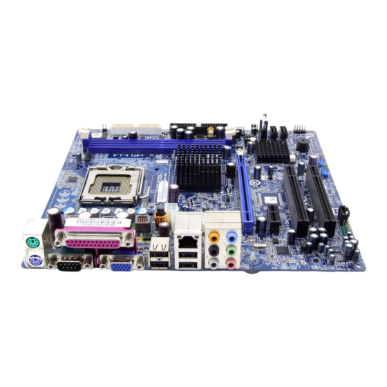
1.8 Connecting Rear Panel I/O Devices The rear I/O part of this motherboard provides the following I/O ports: • Mouse: Connects to PS/2 mouse. • Keyboard: Connects to PS/2 keyboard. • LPT1: Connects to printer or other devices that support this communication protocol. -
Page 17: Bios Setup
2. BIOS Setup This motherboard provides a programmable EEPROM so that you can update the BIOS utility. The BIOS (Basic Input/Output System) is a program that deals with the basic level of communication between processor and peripherals. Use the BIOS Setup program only when installing motherboard, reconfiguring system, or prompted to “Run... -
Page 18: Driver & Utility
3. Driver & Utility The “Driver & Utility CD” that came packed with this motherboard contains drivers, utilities and software applications required for its basic and advanced features. Place the “Driver & Utility CD” into the CD-ROM drive in your system. -
Page 19: Appendix
• 2 個 SATA 3.0Gb/s 支援 SATA RAID 0/1/JBOD 擴充插槽 • 1 個 PCI-E X16 插槽 • 1 個 PCI-E X1 插槽 • 2 個 PCI 插槽 I-S71 內部輸入/輸出接頭 • 1 個軟碟埠 • 1 個 Ultra ATA 133 IDE 接頭 • 2 個 SATA 3.0Gb/s 接頭... -
Page 20: 规格(简体中文
• 1 个 VGA 连接埠 • 4 个 USB 2.0 接头 • 1 个 RJ-45 网络接头 • 1 个 7.1 声道音效接头 RoHS • 100%无铅制程符合 RoHS 规范 其它 • Micro ATX 主机板规格(224mm x 245mm) • 符合 Vista Premium 硬件需求 ※ 本手册的规格与信息若有变动,恕不另行通知。 I-S71... -
Page 21: Troubleshooting (How To Get Technical Support?)
4.3 Troubleshooting (How to Get Technical Support?) 4.3.1 Q & A Do I need to clear the CMOS before I use a new motherboard to assemble my new computer system? Yes, we highly recommend that you clear the CMOS before installing a new motherboard. -
Page 22: Technical Support Form
See the blank Technical Support Form, or visit our website to fill in the form on line (http://www.abit.com.tw/page/en/contact/technical.php). Is the motherboard dead? Do I need to return it to where I bought from or go through an RMA process? After you have gone through the troubleshooting procedures, yet the problem still exists, or you find an evident damage on the motherboard, please contact our RMA center. -
Page 23: Contact Information
Website: http://www.abit-usa.com Latin America: r aymond@abit-usa.com RMA Center: http://rma.abit-usa.com UK, Ireland Universal ABIT UK Co. Ltd. Unit 3, 24-26 Boulton Road, Stevenage, Herts SG1 4QX, United Kingdom Tel: +44-1438-228888 Fax: +44-1438-226333 For technical support and RMA return: Tel: +44-1438-362088 technical@abitcomputer.co.uk returns@abitcomputer.co.uk... - Page 24 P/N: 4310-0000-94 Rev. 2.00...
Need help?
Do you have a question about the I-S71 and is the answer not in the manual?
Questions and answers