Siemens SIMATIC ET 200S Manual
Hide thumbs
Also See for SIMATIC ET 200S:
- Manual (652 pages) ,
- Operating instructions manual (418 pages) ,
- Installation and operating manual (216 pages)
Table of Contents
Advertisement
Quick Links
Power module PM-E DC24V HF
(6ES7138-4CA60-
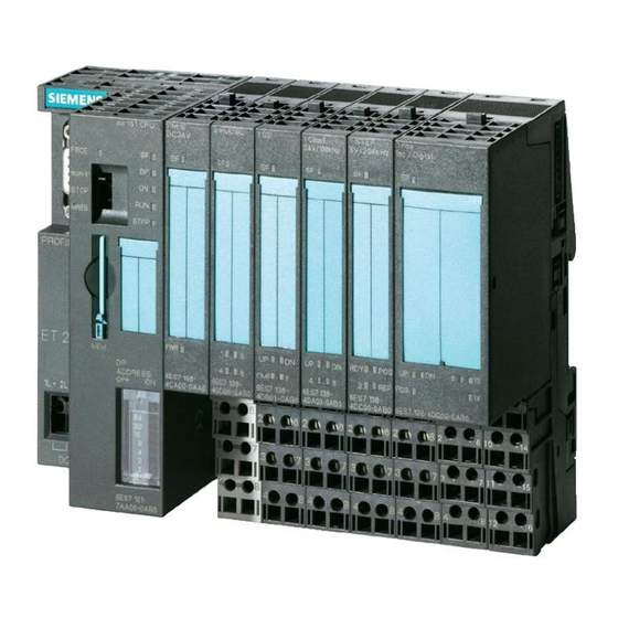
SIMATIC
ET 200S distributed I/O
Power module PM-E DC24V HF
(6ES7138-4CA60-0AB0)
Manual
06/2010
A5E02515369-02
0AB0)
___________________
Preface
___________________
Properties
___________________
Parameters
___________________
Diagnostics
___________________
Configuring
1
2
3
4
Advertisement
Table of Contents

Related Manuals for Siemens SIMATIC ET 200S


Summary of Contents for Siemens SIMATIC ET 200S
- Page 1 ___________________ Power module PM-E DC24V HF Preface (6ES7138-4CA60- 0AB0) ___________________ Properties ___________________ Parameters SIMATIC ___________________ Diagnostics ET 200S distributed I/O ___________________ Power module PM-E DC24V HF Configuring (6ES7138-4CA60-0AB0) Manual 06/2010 A5E02515369-02...
- Page 2 Note the following: WARNING Siemens products may only be used for the applications described in the catalog and in the relevant technical documentation. If products and components from other manufacturers are used, these must be recommended or approved by Siemens. Proper transport, storage, installation, assembly, commissioning, operation and maintenance are required to ensure that the products operate safely and without any problems.
-
Page 3: Preface
Additional support If you have any questions relating to the products described in this manual and do not find the answers in this document, please contact your local Siemens representative (http://www.siemens.com/automation/partners). A guide to the technical documentation for the various SIMATIC products and systems is available on the Internet. - Page 4 You can contact Technical Support for all Industry Automation products by means of the Internet Web form for the Support Request (http://www.siemens.com/automation/csi_en_WW/support_request). Additional information about Siemens Technical Support is available on the Internet (http://www.siemens.com/automation/csi_en_WW/service). Service & Support on the Internet In addition to our documentation, we offer a comprehensive knowledge base on the Internet (http://www.siemens.com/automation/csi_en_WW/support).
-
Page 5: Table Of Contents
Table of contents Preface ..............................3 Properties ..............................7 Power module PM-E DC24V HF (6ES7138-4CA60-0AB0)............7 Parameters .............................. 11 Parameters for PM-E DC24V HF....................11 Diagnostics .............................. 13 Diagnostics using LED display.....................13 Error types............................14 Configuring .............................. 15 Configuring the address space ....................15 Power module PM-E DC24V HF (6ES7138-4CA60-0AB0) Manual, 06/2010, A5E02515369-02... - Page 6 Table of contents Power module PM-E DC24V HF (6ES7138-4CA60-0AB0) Manual, 06/2010, A5E02515369-02...
-
Page 7: Properties
Properties Power module PM-E DC24V HF (6ES7138-4CA60-0AB0) Properties ● The PM-E DC24V HF power module monitors the supply voltage for all electronic modules in the voltage group. The supply voltage is fed in by means of the TM-P terminal module. ●... - Page 8 Properties 1.1 Power module PM-E DC24V HF (6ES7138-4CA60-0AB0) Maximum configuration per voltage group The number of modules that can be connected depends on the total current of all modules in a voltage group. This total must not exceed the maximum current carrying capacity. Address space of inputs/outputs Address space of inputs/outputs by selecting the following as an option: Options...
- Page 9 Properties 1.1 Power module PM-E DC24V HF (6ES7138-4CA60-0AB0) Usable terminal modules Usable terminal modules for PM-E DC24V HF (6ES7138-4CA60-0AB0) TM-P15C23-A1 TM-P15C23-A0 TM-P15C22-01 (6ES7193- (6ES7193-4CD30- (6ES7193-4CE10- Spring terminal 4CC30-0AA0) 0AA0) 0AA0) TM-P15S23-A1 TM-P15S23-A0 TM-P15S22-01 (6ES7193- (6ES7193-4CD20- (6ES7193-4CE00- Screw-type terminal 4CC20-0AA0) 0AA0) 0AA0) TM-P15N23-A1 TM-P15N23-A0...
- Page 10 Properties 1.1 Power module PM-E DC24V HF (6ES7138-4CA60-0AB0) Technical data PM-E DC24V HF (6ES7138-4CA60-0AB0) Dimensions and weight Dimension B (mm) Weight Approx. 35 g Voltages, currents, potentials Rated load voltage 24 VDC Overvoltage protection Protection with automatic circuit breakers Yes, tripping characteristic B, C Max.
-
Page 11: Parameters
Parameters Parameters for PM-E DC24V HF Parameters The following table lists the power module parameters. Table 2- 1 Parameters for power modules PM-E DC24V HF Range of values Default setting Applicability Diagnostics: No load voltage Disable/enable Disable Power module The parameters are explained below. Diagnostics: No load voltage Use this parameter to enable a diagnostic message because there is no load voltage. - Page 12 Parameters 2.1 Parameters for PM-E DC24V HF Power module PM-E DC24V HF (6ES7138-4CA60-0AB0) Manual, 06/2010, A5E02515369-02...
-
Page 13: Diagnostics
Diagnostics Diagnostics using LED display Power module LED displays on the power module: ① Batch error (red) ② Load voltage (green) Status and error displays by means of LEDs on power modules The table below shows the status and error displays on the power module. Event (LEDs) Cause Remedy... -
Page 14: Error Types
Diagnostics 3.2 Error types Error types Power module error types The diagnostic message is reported on channel 0 and applies to the entire module. The table below shows the types of errors affecting power modules Table 3- 1 Power module error types Error type Meaning Remedy... -
Page 15: Configuring
Configuring Configuring the address space Address area for option handling and status byte You can control and monitor option handling, and evaluate the status byte of the power module using the control (PIO) and feedback interface (PII). The address range of the control (PIO) and feedback interface (PII) depends on how the corresponding entry in the configuration software is configured, or which entry has been selected. - Page 16 Configuring 4.1 Configuring the address space Status byte for power modules Figure 4-1 Assignment of status byte for power modules Power module PM-E DC24V HF (6ES7138-4CA60-0AB0) Manual, 06/2010, A5E02515369-02...
Need help?
Do you have a question about the SIMATIC ET 200S and is the answer not in the manual?
Questions and answers