
Related Manuals for Siemens RVP360


Summary of Contents for Siemens RVP360
- Page 1 RVP360 Heating controller for 2 heating circuits and d.h.w. Basic Documentation Edition 2.0 Controller series A CE1P2546en 2017-07-24 Building Technologies...
- Page 2 Published by: © Siemens Switzerland Ltd, 2011 Siemens Switzerland Ltd Delivery and technical specifications subject to change Building Technologies Division International Headquarters Gubelstrasse 22 CH 6301 Zug Switzerland Tel. +41 58 724 24 24 www.siemens.com/sbt 2/106 Siemens Basic Documentation RVP360...
-
Page 3: Table Of Contents
Error handling ..................21 Return temperature (B7) ..............21 4.5.1 Types of sensors.................. 21 4.5.2 Error handling ..................21 Storage tank temperature (B31, B32) ........... 21 4.6.1 Types of sensors.................. 21 3/106 Siemens Basic Documentation RVP360 CE1P2546en Building Technologies Contents 2017-07-24... - Page 4 Optimized switching on ................ 37 9.4.10 Boost heating ..................37 Room functions ..................38 9.5.1 Maximum limitation of room temperature ..........38 9.5.2 Room influence ..................39 Heating curve ..................40 4/106 Siemens Basic Documentation RVP360 CE1P2546en Building Technologies Contents 2017-07-24...
- Page 5 Assignment of d.h.w................57 14.3 Program for the circulating pump ............57 14.4 Frost protection for d.h.w..............57 14.5 Release of d.h.w. heating ..............58 14.5.1 Function ....................58 5/106 Siemens Basic Documentation RVP360 CE1P2546en Building Technologies Contents 2017-07-24...
- Page 6 Simulation of outside temperature ............74 17.3.2 Relay test .................... 74 17.3.3 Sensor test ..................75 17.4 Auxiliary functions ................76 17.4.1 Frost protection for the plant ..............76 17.4.2 Pump overrun ..................76 6/106 Siemens Basic Documentation RVP360 CE1P2546en Building Technologies Contents 2017-07-24...
- Page 7 Mounting choices ................. 98 21.3.3 Electrical installation ................98 Engineering ..................99 22.1 Connection terminals ................99 22.2 Connection diagrams ................. 100 22.2.1 Low-voltage side ................100 22.2.2 Mains voltage side ................100 7/106 Siemens Basic Documentation RVP360 CE1P2546en Building Technologies Contents 2017-07-24...
- Page 8 Mechanical design ................101 23.1 Basic design ..................101 23.2 Dimensions..................101 Addendum..................102 24.1 Technical data..................102 24.2 Revision history ................. 102 8/106 Siemens Basic Documentation RVP360 CE1P2546en Building Technologies Contents 2017-07-24...
-
Page 9: Summary
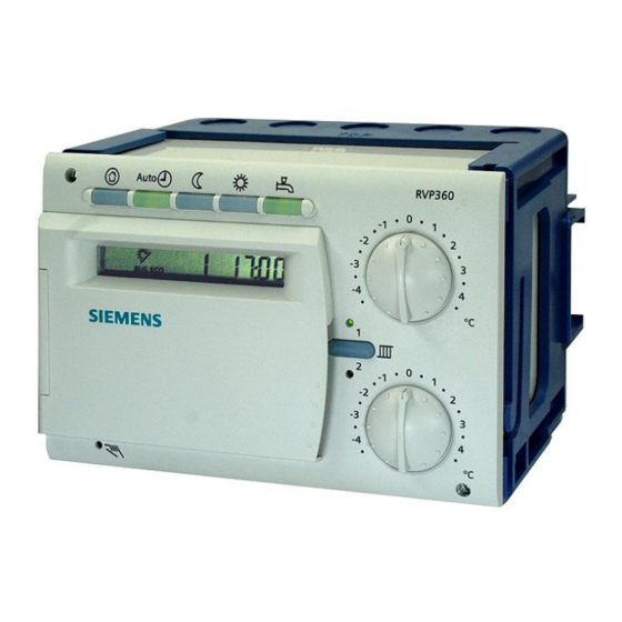
Summary Brief description and key features The RVP360 is a multifunctional heating controller for use in residential and non- residential buildings. It is suited for weather-compensated flow temperature control of 2 heating zones with or without room influence and for demand-dependent boiler temperature control . -
Page 10: Suitable Room Units
Room unit QAA50.110/101 for heating circuits 1 and 2 Room unit QAW70 for heating circuits 1 and 2 1.3.3 Suitable actuators The following types of actuators from Siemens can be used: Electromotoric or electrohydraulic 3-position actuators with a running time of 30...873 seconds 2-position actuators Operating voltage AC 24...230 V... -
Page 11: Use
Interconnected plants consisting of heat generation, several heating zones and central or decentral d.h.w. heating Types of houses and buildings Basically, the RVP360 controller is suited for use in all types of houses and build- ings. But it has been designed specifically for … Multifamily houses, Single-family houses, Small to medium-size nonresidential buildings. -
Page 12: Functions
For the programmed heating and d.h.w. circuits and their possible combinations, refer to chapter 3.2 "Plant types". D.h.w. functions The RVP360 controller is used if one or several of the following d.h.w. functions is/are required: D.h.w. storage tank charging through control of a charging pump, with or without circulating pump D.h.w. -
Page 13: Basics
Key technical features The RVP360 line offers the following key technical features: The RVP360 controller is supplied with 6 programmed plant types. Illustrations of the different plant types are contained in chapter 3.2 "Plant types". The different functions are assigned to the setting levels "End-user", "Heating engineer"... -
Page 14: Plant Types With Regard To D.h.w
With d.h.w. plant type 1 (storage tank with charging pump), electric or solar d.h.w. charging can be activated as an option. 3.2.3 Selectable combinations Type Type of heating circuit Type of d.h.w. heating RVP360 4–0 2 space heating systems with mix- No d.h.w. ing valve 4–1... - Page 15 Room sensor heating circuit 1 Heating circuit pump heating circuit 2 Room sensor heating circuit 2 Controller RVP360 Collector sensor Actuator heating circuit 1 Return sensor Actuator heating circuit 2 Outside sensor 15/106 Siemens Basic Documentation RVP360 CE1P2546en Building Technologies 3 Basics 2017-07-24...
-
Page 16: Setting Levels, Function Blocks, And Plant Types
Frost protection is ensured Reduced operation Continuous heating to the REDUCED temperature With ECO function No holiday mode Remote control via room unit not possible Frost protection is ensured 16/106 Siemens Basic Documentation RVP360 CE1P2546en Building Technologies 3 Basics 2017-07-24... -
Page 17: Heating Modes
Solar d.h.w. heating is always released, independent of the d.h.w. heating mode Manual control The RVP360 controller can be switched to manual control. In that case, automatic control is deactivated. During manual control, the various actuating devices behave as follows:... -
Page 18: Plant Type And Operating Mode
When the operating state is ON, there is a maximum of 3 operating levels, depend- ing on the operating mode. The operating level is determined by the heating pro- gram and the holiday program. 18/106 Siemens Basic Documentation RVP360 CE1P2546en Building Technologies 3 Basics 2017-07-24... -
Page 19: Acquisition Of Measured Values
2 error messages are delivered Automatic selection (operating line 65 = 4): Since the controller itself decides how it acquires the room temperature, no error messages can be delivered 19/106 Siemens Basic Documentation RVP360 CE1P2546en Building Technologies 4 Acquisition of measured values 2017-07-24... -
Page 20: Room Model
For more details, refer to chapter 9.4.6 "Room model temperature". Flow temperature (B1, B12) 4.2.1 Types of sensors Suitable are Siemens sensors operating with a sensing element LG-Ni1000. Averaging with 2 sensors is not possible. 4.2.2 Error handling A flow sensor with a short-circuit or an interruption always leads to an error mes- sage, irrespective of the type of plant. -
Page 21: Error Handling
Return temperature (B7) 4.5.1 Types of sensors Suitable are Siemens sensors operating with a sensing element LG-Ni1000. This measured value is required for the minimum limitation of the return tempera- ture. In interconnected plants, the return temperature with plant type 4 - x can be ac- quired via data bus. -
Page 22: Error Handling
If a measured value of the d.h.w. temperature is not available and the temperature is queried, the QAW70 room unit displays ---. 22/106 Siemens Basic Documentation RVP360 CE1P2546en Building Technologies 4 Acquisition of measured values 2017-07-24... -
Page 23: Collector Temperature (B6)
Collector temperature (B6) 4.7.1 Type of sensor The collector temperature is acquired by a Siemens sensor operating with a sens- ing element LG-Ni1000 and an extended measuring range. 4.7.2 Error handling In the event of an interruption of the measuring circuit, an error message is deliv- ered with a delay of 12 hours, and the collector pump is deactivated. -
Page 24: Function Block: End-User Space Heating
ECO function – if available – aborts the OFF mode until the room temperature has risen 1 °C above the setpoint for holi- day/protection mode. 24/106 Siemens Basic Documentation RVP360 CE1P2546en Building Technologies 5 Function block: End-user space heating 2017-07-24... -
Page 25: Heating Program
The holiday program is only active in AUTO mode. Heating curve The heating curve can be adjusted on operating lines 14 and 15. For more detailed information, refer to chapter 9.6 "Heating curve". 25/106 Siemens Basic Documentation RVP360 CE1P2546en Building Technologies 5 Function block: End-user space heating 2017-07-24... -
Page 26: Function Block: End-User D.h.w
REDUCED setpoint (operating line 28). Note When using thermstats, the REDUCED setpoint of the d.h.w. temperature is deac- tivated since the thermostat determines the switch on/off temperature. 26/106 Siemens Basic Documentation RVP360 CE1P2546en Building Technologies 6 Function block: End-user d.h.w. 2017-07-24... -
Page 27: Actual Value
(B31 and B32), the temperature of the ”warmer” sensor is displayed. When using thermostats, the actual value of the d.h.w. temperature cannot be dis- played. In that case, the display shows ---. 27/106 Siemens Basic Documentation RVP360 CE1P2546en Building Technologies 6 Function block: End-user d.h.w. 2017-07-24... -
Page 28: Function Block: End-User General
The entries are sorted and overlapping ON phases are combined. Time of day and date The RVP360 has a yearly clock for entering the time of day, the weekday and the date. The weekday on operating line 39 is automatically determined according to the set date and cannot be changed. -
Page 29: Faults
= error number = segment number (LPB) = device number (LPB) The error message disappears only after the fault has been rectified. There is no acknowledgement! 29/106 Siemens Basic Documentation RVP360 CE1P2546en Building Technologies 7 Function block: End-user general 2017-07-24... -
Page 30: Function Block: Plant Configuration
All plant-specific variables and operating lines for use with the other plant types will be hidden. They will not appear on the display. Example of entry: = heating circuit type 5 = d.h.w. type 1 30/106 Siemens Basic Documentation RVP360 CE1P2546en Building Technologies 8 Function block: Plant configuration 2017-07-24... -
Page 31: Function Block: Space Heating
This means that – in comparison with the current outside temperature – the attenuated outside tem- perature is considerably dampened. This ensures that no heating is provided in 31/106 Siemens Basic Documentation RVP360 CE1P2546en Building Technologies 9 Function block: Space heating 2017-07-24... -
Page 32: Heating Limits
In both cases, the heating limit is the outside temperature at which the heating shall be switched on or off. The switching differential is 1 °C. 32/106 Siemens Basic Documentation RVP360 CE1P2546en Building Technologies 9 Function block: Space heating 2017-07-24... -
Page 33: Mode Of Operation
2 = controller operates with room sensor connected to terminal B5 or B52 3 = controller operates with the mean value of the devices connected to terminals A6 and B5, or A6 and B52 33/106 Siemens Basic Documentation RVP360 CE1P2546en Building Technologies 9 Function block: Space heating 2017-07-24... -
Page 34: Optimization
Without room sensor, only optimized switching on is possible. Optimization operates with fixed values (no learning process), based on the set maximum heating up time and the room model. 34/106 Siemens Basic Documentation RVP360 CE1P2546en Building Technologies 9 Function block: Space heating 2017-07-24... -
Page 35: Process
The room temperature used by the room model is calculated according to the following formula: Room model temperature T [°C] = (T – T ) × e 3 × kt 35/106 Siemens Basic Documentation RVP360 CE1P2546en Building Technologies 9 Function block: Space heating 2017-07-24... -
Page 36: Optimized Switching Off
(- ln ———————— ) where: Natural logarithm Building time constant in hours Duration of quick setback Composite outside temperature Setpoint for NORMAL room temperature Setpoint for REDUCED room temperature 36/106 Siemens Basic Documentation RVP360 CE1P2546en Building Technologies 9 Function block: Space heating 2017-07-24... -
Page 37: Optimized Switching On
NORMAL heating. Then, this setpoint applies again Without room sensor, the room model calculates how long boost heating will be maintained. The duration is calculated according to the following formula: 37/106 Siemens Basic Documentation RVP360 CE1P2546en Building Technologies 9 Function block: Space heating 2017-07-24... -
Page 38: Room Functions
[K] = T ( 1 + s ) Rw * -0,5 Heating curve slope Room temperature setpoint reduction Deviation of the room temperature Flow temperature setpoint reduction 38/106 Siemens Basic Documentation RVP360 CE1P2546en Building Technologies 9 Function block: Space heating 2017-07-24... -
Page 39: Room Influence
Reduction of room temperature setpoint Increase of room temperature setpoint Actual value of room temperature Deviation of room temperature (T Change of flow temperature setpoint Gain factor 39/106 Siemens Basic Documentation RVP360 CE1P2546en Building Technologies 9 Function block: Space heating 2017-07-24... -
Page 40: Heating Curve
Setting operating line 14, flow temperature setpoint at an outside temperature of 15 °C BZ 15 Setting operating line 15, flow temperature setpoint at an outside temperature of -5 °C Outside temperature Flow temperature setpoint 40/106 Siemens Basic Documentation RVP360 CE1P2546en Building Technologies 9 Function block: Space heating 2017-07-24... -
Page 41: Deflection
Parallel displacement T = ( T ( 1 + s ) Flow Knob Parallel displacement of heating curve Slope Outside temperature Flow temperature Room temperature setpoint 41/106 Siemens Basic Documentation RVP360 CE1P2546en Building Technologies 9 Function block: Space heating 2017-07-24... -
Page 42: Generation Of Setpoint
Heating curve slope Room temp. setpoint holiday / protection The impact of the central unit OZW30 is described in chapter 20.1.4 "Interplay with SYNERGYR central unit OZW30". 42/106 Siemens Basic Documentation RVP360 CE1P2546en Building Technologies 9 Function block: Space heating 2017-07-24... -
Page 43: Function Block: Pump Heating Circuit
The on time of the heating circuit pump is limited as follows: The pump’s minimum on time is 3 minutes If the calculated on time exceeds 8 minutes, the pump runs continuously 43/106 Siemens Basic Documentation RVP360 CE1P2546en Building Technologies 10 Function block: Pump heating circuit 2017-07-24... -
Page 44: Function Block: Actuator Heating Circuit
Both limitations can be deactivated (setting ---). Impact on d.h.w. Minimum limitation can be overridden during storage tank charging, depending on heating the type of priority. 44/106 Siemens Basic Documentation RVP360 CE1P2546en Building Technologies 11 Function block: Actuator heating circuit 2017-07-24... -
Page 45: Setpoint Increase
In the case of space heating with a pump heating circuit (plant type 6 - x), maxi- mum limitation of the setpoint increase is not possible. This function can be deactivated (setting ---). 45/106 Siemens Basic Documentation RVP360 CE1P2546en Building Technologies 11 Function block: Actuator heating circuit 2017-07-24... -
Page 46: Type Of Actuator
The flow temperature is controlled via the modulating actuating device (mixing valve or 2-port valve). There is no proportional offset, owing to the control system’s I-action. 46/106 Siemens Basic Documentation RVP360 CE1P2546en Building Technologies 11 Function block: Actuator heating circuit 2017-07-24... -
Page 47: Auxiliary Variables In Interconnected Plants
This minimizes strain on the actuator. For safety reasons, however, the controller sends a 1-minute CLOSE pulse at 10-minute intervals. A pulse in the opposite direction negates the pulse lock. 47/106 Siemens Basic Documentation RVP360 CE1P2546en Building Technologies 11 Function block: Actuator heating circuit 2017-07-24... -
Page 48: Function Block: Boiler
If there is demand for heat, the boiler always supplies heat, which means that the boiler's operating mode in that case is always ON. 48/106 Siemens Basic Documentation RVP360 CE1P2546en Building Technologies 12 Function block: Boiler 2017-07-24... -
Page 49: Limitations
If the boiler temperature is limited to a minimum, the display shows 12.3.3 Actions during d.h.w. heating Maximum and minimum limitation are also active during d.h.w. heating. 49/106 Siemens Basic Documentation RVP360 CE1P2546en Building Technologies 12 Function block: Boiler 2017-07-24... -
Page 50: 2-Position Control
Actual value of boiler temperature Boiler temperature Burner control signal Note on setting: When controlling a 1-stage burner, the reset integral of the second stage should be set to zero. 50/106 Siemens Basic Documentation RVP360 CE1P2546en Building Technologies 12 Function block: Boiler 2017-07-24... -
Page 51: Control With 2-Stage Burner
Due to the time-temperature integral, it is not only the duration of the deviation that is considered but also its extent when deciding whether the second stage shall be released or locked. 51/106 Siemens Basic Documentation RVP360 CE1P2546en Building Technologies 12 Function block: Boiler 2017-07-24... -
Page 52: Frost Protection For The Boiler
If the integral falls below a defined level, the boiler pump is activated again. The connected consumers increase their setpoints again. 52/106 Siemens Basic Documentation RVP360 CE1P2546en Building Technologies 12 Function block: Boiler 2017-07-24... -
Page 53: Protection Against Boiler Overtemperatures
Plant types with heating circuits using a mixing valve/2-port valve maintain the previous setpoint Plant types with pump heating circuits allow the pumps to run 53/106 Siemens Basic Documentation RVP360 CE1P2546en Building Technologies 12 Function block: Boiler 2017-07-24... -
Page 54: Operating Mode Of Pump M1
Circulating pump with deactivation (setting 1): The circulating pump runs when one of the consumers requests the boiler to supply heat. During protective boiler startup, the pump is deactivated 54/106 Siemens Basic Documentation RVP360 CE1P2546en Building Technologies 12 Function block: Boiler 2017-07-24... -
Page 55: Function Block: Setpoint Return Temperature Limitation
13.3.1 Type of sensor Suitable are Siemens sensors operating with a sensing element LG-Ni1000. The sensor is to be installed in the return. With plant type 4 - x, the return temperature signal can also be forwarded via LPB. -
Page 56: Mode Of Operation With An Autonomous Unit (Without Bus)
(For response to critical locking signals, refer to chapter 17.4.5 "Locking signal gain"). 56/106 Siemens Basic Documentation RVP360 CE1P2546en Building Technologies 13 Function block: Setpoint return temperature limitation 2017-07-24... -
Page 57: Function Block: D.h.w
The switch-off temperature is 5 °C plus the switching differential (set on operating line 128). Caution! When using thermostats, frost protection for the d.h.w. storage tank is not provided. 57/106 Siemens Basic Documentation RVP360 CE1P2546en Building Technologies 14 Function block: D.h.w. 2017-07-24... -
Page 58: Release Of D.h.w. Heating
– and not the times entered. The release of d.h.w. heating is explained on the basis of 2 examples, where con- trollers A and B are interconnected via data bus: 58/106 Siemens Basic Documentation RVP360 CE1P2546en Building Technologies 14 Function block: D.h.w. 2017-07-24... -
Page 59: Heating During Holiday Periods
Priority and flow temperature setpoint 14.6.1 Settings Op. line D.h.w. priority Flow temperature setpoint according to … Absolute d.h.w. Shifting d.h.w. Shifting maximum selection None (parallel) d.h.w. None (parallel) maximum selection 59/106 Siemens Basic Documentation RVP360 CE1P2546en Building Technologies 14 Function block: D.h.w. 2017-07-24... -
Page 60: Priority
If the heat source is located in segment 1…14, it only sends the signal to the controllers in the same segment 60/106 Siemens Basic Documentation RVP360 CE1P2546en Building Technologies 14 Function block: D.h.w. -
Page 61: No Priority
126. It can be captured with 1 or 2 sensors, or with 1 or 2 thermostats. In the case of plants without solar d.h.w. heating, settings 0 to 3 are available; with solar d.h.w. heating, setting 4 or 5: 61/106 Siemens Basic Documentation RVP360 CE1P2546en Building Technologies 14 Function block: D.h.w. 2017-07-24... - Page 62 If the storage tank is equipped with a thermostat, it is the thermostat that deter- mines the switch-on/off temperature. 62/106 Siemens Basic Documentation RVP360 CE1P2546en Building Technologies 14 Function block: D.h.w. 2017-07-24...
-
Page 63: Boost Of D.h.w. Charging Temperature
- SD Lmax Lmax Charging locked Maximum charging time Lmax D.h.w. charging D.h.w. temperature D.h.w. charging ON D.h.w. temperature setpoint OFF D.h.w charging OFF Switching differential d.h.w. Time 63/106 Siemens Basic Documentation RVP360 CE1P2546en Building Technologies 14 Function block: D.h.w. 2017-07-24... -
Page 64: Setpoint Legionella Function
Common flow temperature of the same segment via data bus.* Otherwise, there is no pump overrun due to protection against discharging 5–1 Sensor B2 6–1 Sensor B2 64/106 Siemens Basic Documentation RVP360 CE1P2546en Building Technologies 14 Function block: D.h.w. 2017-07-24... -
Page 65: Manual D.h.w. Charging
If d.h.w. heating shall be switched off again after manual charging, the button must be pressed again after it flashes (button extinguishes). Manual charging is not possible when heating the d.h.w. with an electric immersion heater. 65/106 Siemens Basic Documentation RVP360 CE1P2546en Building Technologies 14 Function block: D.h.w. 2017-07-24... -
Page 66: Function Block: Multifunctional Relay
Function block: Multifunctional relay The RVP360 controller is equipped with a multifunctional relay K6 whose function is selected with this block. This relay is also used for the control of a circulating pump, a collector pump, or an electric immersion heater for d.h.w. heating. -
Page 67: Relay Energized In The Event Of Fault
(heating circuit) A (HC1) 06:00...18:00 Circulating pump runs A (HC2) 03:00...22:00, holi- from 06:00 days to 23:00 B (HC1) 07:00...22:00 B(HC2) 07:00...23:00 67/106 Siemens Basic Documentation RVP360 CE1P2546en Building Technologies 15 Function block: Multifunctional relay 2017-07-24... -
Page 68: Collector Pump
The storage tank sensor(s) used is (are) selected via operating line 126. The settings required for solar d.h.w. charging must be made via operating lines 201 – 208. 68/106 Siemens Basic Documentation RVP360 CE1P2546en Building Technologies 15 Function block: Multifunctional relay 2017-07-24... -
Page 69: Type Of D.h.w. Charging
Heat requests from all controllers connected to the data bus (LPB), including those from the controller’s own heating circuit 69/106 Siemens Basic Documentation RVP360 CE1P2546en Building Technologies 15 Function block: Multifunctional relay 2017-07-24... -
Page 70: Function Block: Legionella Function
Operating line 149 is used to define for what period of time the actual value of the d.h.w. temperature must lie above the legionella setpoint (operating line130) for the function to be considered fulfilled. 70/106 Siemens Basic Documentation RVP360 CE1P2546en Building Technologies 16 Function block: Legionella function 2017-07-24... -
Page 71: Operation Of Circulating Pump
On completion of the overriding function, d.h.w. charging to the legionella setpoint is started since release of the legionella function is maintained. 71/106 Siemens Basic Documentation RVP360 CE1P2546en Building Technologies 16 Function block: Legionella function 2017-07-24... - Page 72 The maximum d.h.w. temperature setpoint has no impact on the legionella setpoint. 72/106 Siemens Basic Documentation RVP360 CE1P2546en Building Technologies 16 Function block: Legionella function 2017-07-24...
-
Page 73: Function Block: Service Functions And General Settings
The reading is limited to a maximum of 500,000 hours (57 years). 17.2.2 Software version The display shows the software version currently used by the controller. 73/106 Siemens Basic Documentation RVP360 CE1P2546en Building Technologies 17 Function block: Service functions and general settings 2017-07-24... -
Page 74: Commissioning Aids
By leaving the setting level by pressing By leaving the setting level by pressing any of the operating mode buttons Automatically after 30 minutes 74/106 Siemens Basic Documentation RVP360 CE1P2546en Building Technologies 17 Function block: Service functions and general settings 2017-07-24... -
Page 75: Sensor Test
– – – = interruption (thermostat: contact open) When changing from operating line 163 to 164, and vice versa, the selected sensor (setting 0…11) is maintained. 75/106 Siemens Basic Documentation RVP360 CE1P2546en Building Technologies 17 Function block: Service functions and general settings 2017-07-24... -
Page 76: Auxiliary Functions
In interconnected plants, the set time also affects the forced signals that a boiler can deliver to ensure overtemperature protection. For more detailed information, refer to chapter 12.4.5 "Protection against boiler overtemperatures". 76/106 Siemens Basic Documentation RVP360 CE1P2546en Building Technologies 17 Function block: Service functions and general settings 2017-07-24... -
Page 77: Pump Kick
In plants using a diverting valve, the valve is driven to the d.h.w. position 77/106 Siemens Basic Documentation RVP360 CE1P2546en Building Technologies 17 Function block: Service functions and general settings... - Page 78 Consumers with pump circuit: When the critical locking signal reaches a defined value, the pump is deactivat- ed, independent of the set locking signal gain. 78/106 Siemens Basic Documentation RVP360 CE1P2546en Building Technologies 17 Function block: Service functions and general settings 2017-07-24...
-
Page 79: Inputs For Lpb
Per system, only 1 controller may be used as a master. If several controllers are parameterized as masters, an error message is delivered (error code 100). 79/106 Siemens Basic Documentation RVP360 CE1P2546en Building Technologies 17 Function block: Service functions and general settings... -
Page 80: Outside Temperature Source
If an inadmissible address has been entered for the selected plant type, an error message appears (error code 140). For detailed information about addressing devices, refer to Data Sheet N2030. 80/106 Siemens Basic Documentation RVP360 CE1P2546en Building Technologies 17 Function block: Service functions and general settings 2017-07-24... -
Page 81: Bus Power Supply
17.5.5 Bus loading number The bus loading number E of the RVP360 for the LPB is as follows: RVP360 = 10 The sum of all bus loading numbers E of all devices connected to the same bus must not exceed 300. -
Page 82: Function Block: Solar D.h.w
– 18.2 General In the case of plant types equipped with a d.h.w. storage tank, the RVP360 sup- ports solar d.h.w. heating. The function is activated … when function "D.h.w. storage tank sensor" (operating line 126, setting 4 "Solar d.h.w. -
Page 83: Functions
(SD – SD ) (and when the re- quired switch-on differential is reached): TKol > TLmin + (SD – SD 83/106 Siemens Basic Documentation RVP360 CE1P2546en Building Technologies 18 Function block: Solar d.h.w. 2017-07-24... -
Page 84: Minimum Running Time
TKol < TKolFrost The collector pump is deactivated when the collector temperature rises 1 K above the frost protection temperature: TKol > TKolFrost + 1 K 84/106 Siemens Basic Documentation RVP360 CE1P2546en Building Technologies 18 Function block: Solar d.h.w. 2017-07-24... -
Page 85: Overtemperature Protection For The Collector
TSp < TSpSi – 1 K If 2 storage tank sensors are used, the sensor acquiring the highest temperature is considered. Setting --- deactivates overtemperature protection for the collector. 85/106 Siemens Basic Documentation RVP360 CE1P2546en Building Technologies 18 Function block: Solar d.h.w. 2017-07-24... -
Page 86: Storage Tank Recooling
TKol > TSp – 2 K If the storage tank temperature reaches a level of 1 K above the recooling setpoint, the function is ended: TSp < TRk + 1 K 86/106 Siemens Basic Documentation RVP360 CE1P2546en Building Technologies 18 Function block: Solar d.h.w. 2017-07-24... -
Page 87: Evaporation Temperature Of Heat Conducting Medium
TSp < TSpMax – 1 K Overtemperature protection for the collector can again activate the collector pump Note until the storage tank temperature reaches its maximum limit value. 87/106 Siemens Basic Documentation RVP360 CE1P2546en Building Technologies 18 Function block: Solar d.h.w. 2017-07-24... -
Page 88: Maximum Limitation Of Storage Tank Temperature
TKol t < Grad TKol Collector temperature Grad Gradient ON/OFF Collector pump Temperature Time Setting --- deactivates the collector start function. 88/106 Siemens Basic Documentation RVP360 CE1P2546en Building Technologies 18 Function block: Solar d.h.w. 2017-07-24... -
Page 89: Function Block: Locking Functions
(only for leaving the setting level), the button for manual control. 89/106 Siemens Basic Documentation RVP360 CE1P2546en Building Technologies 19 Function block: Locking functions 2017-07-24... -
Page 90: Communication
With the knob of the QAA50.110/101, the room temperature setpoint for NORMAL ature readjustments heating can be readjusted by ±3 °C. The QAA50.110/101 does not affect adjustment of the room temperature setpoint on the controller’s operating line 1. 90/106 Siemens Basic Documentation RVP360 CE1P2546en Building Technologies 20 Communication 2017-07-24... -
Page 91: Interplay With Room Unit Qaw70
Time of day and weekday Complete heating program Room temperature setpoint for NORMAL heating Room temperature setpoint for REDUCED heating D.h.w. temperature setpoint Hence, the controller is always the data master. 91/106 Siemens Basic Documentation RVP360 CE1P2546en Building Technologies 20 Communication 2017-07-24... - Page 92 For heating circuit 2, address 2 must be entered Identification of room unit Operating lock on QAW70 No impact on the controller Type of setpoint display No impact on the controller 92/106 Siemens Basic Documentation RVP360 CE1P2546en Building Technologies 20 Communication 2017-07-24...
-
Page 93: Interplay With Synergyr Central Unit Ozw30
The heating circuit that shall be acted upon must be selected on the OZW30. 20.2 Communication with other devices The RVP360 offers the following communication choices: Signalling the heat demand of several RVP360 to the heat source Exchange of locking and forced signals Exchange of measured values, such as outside temperature, return temperature... -
Page 94: Handling
Knob for readjusting the room temperature setpoint of heating circuit 1 Button for switching between the heating circuits Knob for readjusting the room temperature setpoint of heating circuit 2 Buttons for adjusting values 94/106 Siemens Basic Documentation RVP360 CE1P2546en Building Technologies 21 Handling 2017-07-24... -
Page 95: Operating Elements
The active heating circuit is indicated circuits by an LED. If both heating circuits are active, both LEDs are lit. 95/106 Siemens Basic Documentation RVP360 CE1P2546en Building Technologies 21 Handling 2017-07-24... - Page 96 This is made possible by using 2 button combinations: Action Effect Selection of next higher function block Keep depressed and press Selection of next lower function block Keep depressed and press 96/106 Siemens Basic Documentation RVP360 CE1P2546en Building Technologies 21 Handling 2017-07-24...
-
Page 97: Setting Levels And Access Rights
This input activates all functions and settings required for the selected type of plant. Setting the other All operating lines contain proven and practice-oriented values. The Installation operating lines Instructions show codings and give guide values, comments, etc., where required. 97/106 Siemens Basic Documentation RVP360 CE1P2546en Building Technologies 21 Handling 2017-07-24... -
Page 98: Installation
In the sloping front of a control desk 21.3.2 Mounting choices RVP360 can be mounted in one of 3 different ways: Wall mounting: The base is secured to a flat wall with 3 screws Rail mounting: The base is snapped on a top hat rail Flush-panel mounting: The base is fitted in a panel cutout measuring 138 x 92 mm. -
Page 99: Engineering
Heating circuit mixing valve heating circuit 2 OPEN Heating circuit mixing valve heating circuit 2 CLOSE In addition to the standard connection terminals, auxiliary terminals for N and are provided 99/106 Siemens Basic Documentation RVP360 CE1P2546en Building Technologies 22 Engineering 2017-07-24... -
Page 100: Connection Diagrams
LPB Data bus Circulating pump Heating circuit pump heating circuit 1 Storage tank charging pump Heating circuit pump heating circuit 2 Controller RVP360 Actuator heating circuit 1 Actuator heating circuit 2 100/106 Siemens Basic Documentation RVP360 CE1P2546en Building Technologies 22 Engineering 2017-07-24... -
Page 101: Mechanical Design
On the inner side of the cover, there is a holder where the Operating Instructions can be inserted. The RVP360 has the standard overall dimensions 96 mm x 144 mm. It can be mounted in one of 3 different ways:... -
Page 102: Addendum
For technical data, refer to Data Sheet N2546. 24.2 Revision history Edition 1.0 is the first publication of this document. So there are no alterations against any previous editions. 102/106 Siemens Basic Documentation RVP360 CE1P2546en Building Technologies 24 Addendum 2017-07-24... - Page 103 Flush-panel mounting ......... 98 Forced charging ..........64 Collector pump..........68, 84 Collector sensor ..........23 Forced signal ............53 Frost protection for d.h.w........57 Collector start function ........88 103/106 Siemens Basic Documentation RVP360 CE1P2546en Building Technologies Index 2017-07-24...
- Page 104 Interruption ............19 Overlapping heating phases ........25 Overrun ...............64 Overtemperature protection for the collector ..85 Knob ..............95 Knob for readjustments QAW70 ......91 Parallel displacement of heating curve ....41 104/106 Siemens Basic Documentation RVP360 CE1P2546en Building Technologies Index 2017-07-24...
- Page 105 Wall mounting............. 98 Sealing ............. 101 Winter-/summertime changeover ......77 Selecting the plant type ........30 Wintertime ............. 28, 77 Sensor test ............75 Wiring ..............97 Service functions..........73 105/106 Siemens Basic Documentation RVP360 CE1P2546en Building Technologies Index 2017-07-24...
- Page 106 Published by: © Siemens Switzerland Ltd, 2011 Siemens Switzerland Ltd Delivery and technical specifications subject to change Building Technologies Division International Headquarters Gubelstrasse 22 CH 6301 Zug Switzerland Tel. +41 58 724 24 24 www.siemens.com/sbt 106/106 Siemens Basic Documentation RVP360...
Need help?
Do you have a question about the RVP360 and is the answer not in the manual?
Questions and answers