Table of Contents
Advertisement
Quick Links
en
Installation Instructions
Installation
Place of installation
•
In a dry room, e.g. in the boiler room
•
Mounting choices:
−
Control cabinet (in the front, on the inner wall, or on a
DIN rail)
−
Control panel
−
In the sloping front of a control desk
•
Permissible ambient temperature: 0...50 °C
Electrical installation
•
The local regulations for electrical installations must be
complied with
•
Cable tension relief must be ensured
•
The cables from the controller to the actuators and
pumps carry mains voltage
•
The cables to the sensors should not be run parallel to
mains carrying cable
Permissible cable lengths
•
For all sensors and thermostats:
Copper cable 0.6 mm dia. max. 20 m
2
Copper cable 1.0 mm
2
Copper cable 1.5 mm
•
For the room units:
2
Copper cable 0.25 mm
2
Copper cable 0.5 mm
Mounting and wiring the base
Wall mounting
1. Separate base from the controller.
2. Hold base against the wall. Marking «TOP» must be at
the top!
3. Mark fixing holes on the wall.
4. Drill holes.
5. If required, knock out holes on the base for cable entry
glands.
6. Screw base to the wall.
7. Wire up base.
DIN rail mounting
1. Fit rail.
2. Separate base from the controller.
3. If required, knock out holes on the base for cable entry
glands.
4. Fit base to the rail. Marking «TOP» must be at the top!
5. If required, secure base (depending on the type of rail
used).
6. Wire up base.
Flush panel mounting
•
Required panel cutout: 92 × 138 mm
•
Maximum thickness: 3 mm
1. Separate base from the controller.
2. If required, knock out holes on the base for cable entry
glands.
3. Insert base in the panel cutout from behind until stop
is reached. Marking «TOP» must be at the top!
4. Push lateral tongues behind the front panel (refer to
illustration below).
5. Wire up base. Make sure the cable lengths are such
that there is sufficient space to open the control panel
door.
Building Technologies / HVP Products
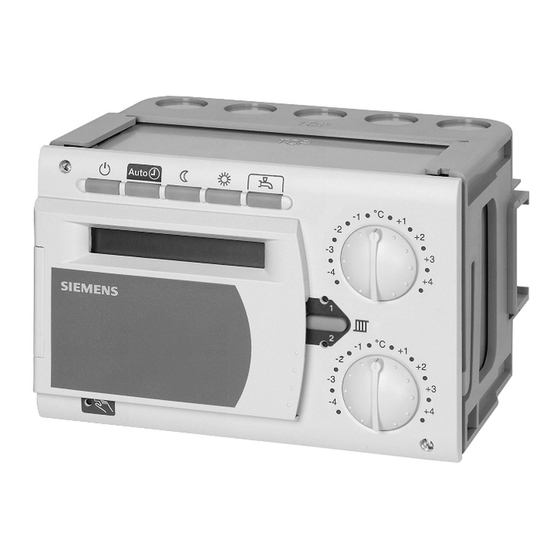
Heating controller
max. 80 m
max. 120 m
max. 25 m
max. 50 m
74 319 0165 0 a
Wrong
Place tongues on both sides correctly – they may not be
located inside the cutout!
Commissioning
Preparatory checks
1. DO NOT switch on power yet.
2. Check wiring according to the plant connection dia-
gram.
3. Ensure correct position and location of the levers by
turning the fixing screws (refer to illustration on the lat-
eral wall of the unit):
4. Insert controller in the base until stop is reached.
Marking «TOP» must be at the top!
5. Tighten fixing screws alternately.
6. Check the motorized valve: see if
−
it is correctly installed (observe direction of flow in-
dicated on the valve body)
−
in the case of a slipper valve, the slipper turns in the
correct angular range (note position indicator)
−
the manual lever is disengaged
7. Note with underfloor and ceiling heating systems!
The limit thermostat must be set to the correct value.
During the functional test, the flow temperature may
not exceed the maximum permissible level (usually
55 °C). If it does, proceed immediately as follows:
−
Either close the valve manually, or
−
Switch off the pump, or
−
Close the pump isolating valve
8. Switch on power. The display must show something
(e.g. the time of day). If not, the reason is probably
one of the following:
−
No mains voltage
−
Main fuse defective
−
Mains isolator or main switch not ON
9. Addressing to be made on the room units:
−
Room unit heating circuit 1 = address 1
−
Room unit heating circuit 2 = address 2
10. If one of the operating mode buttons flashes, a room
unit overrides the controller. Select operating mode
on the room unit.
CE1G2478en
74 319 0165 0
G2478
RVP331
Correct
31.01.2006
1/8
Advertisement
Table of Contents

Related Manuals for Siemens RVP331


Summary of Contents for Siemens RVP331
- Page 1 74 319 0165 0 G2478 RVP331 Heating controller Installation Instructions Installation Place of installation • In a dry room, e.g. in the boiler room • Mounting choices: − Control cabinet (in the front, on the inner wall, or on a DIN rail) −...
- Page 2 Flow sensor, heating circuit 1 Outside sensor Heating circuit pump, heating circuit 2 B12 Flow sensor, heating circuit 2 Two-stage burner Controller RVP331 Boiler sensor Limit thermostat Actuator, heating circuit 1 B31 Storage tank sensor / thermostat Manual reset safety limit thermostat...
- Page 3 Mains voltage side F1/F2 Settings Legend for the setting tables: Adjustable Display only Line Function, display Default Range Setting Explanations, notes and tips Settings on the «End-user» level Press to activate the «End-user» level. Setpoint of NORMAL heating 20.0 °C 0...35 ..
- Page 4 Line Function, display Default Range Setting Explanations, notes and tips 36 Start of third «ON period» --:-- 00:00...24:00 Switching program 2 ..: ..--:-- = period inactive 37 End of third «ON period» --:-- 00:00...24:00 Switching program 2 ..: ..--:-- = period inactive 38 Time of day 00:00...23:59...
- Page 5 Flow sensor, heating circuit 2 Load (room 1) Heating circuit pump, heating circuit 2 Boiler sensor Load (room 2) Controller RVP331 Storage tank sensor / thermostat Heat source (boiler) Heating circuit valve, heating circuit 1 Room sensor, heating circuit 1...
- Page 6 Line Function, display Default Range Setting Explanations, notes and tips 0 = with room model 66 Type of optimisation 0 / 1 ....1 = with room unit / room sensor Setting 0 only permits optimum start control 67 Max. heating up time 00:00 h 00:00...42:00 Max.
- Page 7 Line Function, display Default Range Setting Explanations, notes and tips Block «D.h.w.» 0 = 24 h per day 123 Release of d.h.w. heating 0...2 1 = according to the heating program; ..start of release is always shifted forward by one hour 2 = according to switching program 2 124 D.h.w.
- Page 8 Function of switching program 2 – 3. Insert the Operating Instructions in the unit cover. Dimensions max. 3 26 26 26 26 106,8 Dimensions in mm © 2000 Siemens Building Technologies Ltd. 31.01.2006 CE1G2478en 74 319 0165 0 a Building Technologies / HVP Products...
Need help?
Do you have a question about the RVP331 and is the answer not in the manual?
Questions and answers