Table of Contents
Advertisement
Quick Links
- 1 System Overview and General Specification
- 2 Electrical Installation of Controller
- 3 Installation of Plc Interface for Extended Controller Lpc-200.2
- 4 System Operation with Lpc-200.1 (Stand-Alone Controller)
- 5 Troubleshooting for Operation with Controller Lpc-200.1
- 6 Troubleshooting with Service Software
- 7 Technical Support
- Download this manual
This manual contains information necessary for the safe and proper use of the BPS-200.
Included are specifications for the standard configurations of the pump system and
instructions regarding its use, installation, operation, adjustment, inspection and main-
tenance. For special configurations of the pump system refer to accompanying information.
Please familiarize yourself with the contents of the manual to ensure the safe and effective
use of this product. After reading this manual, please store the manual where the personnel
responsible for operating the pump system can readily refer to it at any time.
PL-4012-00, Rev01,DCO# 09-188
BPS-200
2.6 bar
21 liters/min
USER MANUAL
Levitronix
(37.7 psi)
(5.5 gallons/min)
®
Bearingless Pumps
www.levitronix.com
Advertisement
Table of Contents

Related Manuals for Levitronix BPS-200


Summary of Contents for Levitronix BPS-200
- Page 1 (5.5 gallons/min) USER MANUAL This manual contains information necessary for the safe and proper use of the BPS-200. Included are specifications for the standard configurations of the pump system and instructions regarding its use, installation, operation, adjustment, inspection and main- tenance.
-
Page 2: Table Of Contents
User Manual for BPS-200 www.levitronix.com Table of Contents SAFETY PRECAUTIONS ......................... 3 SPECIFICATIONS............................. 4 System Overview and General Specification ..................4 HYDRAULIC SPECIFICATIONS ......................7 3.1.1 Pressure-Flow Curves ....................... 7 General Environmental Conditions....................7 Basic Dimensions of Main Components.................... 8 ENGINEERING INFORMATION ...................... -
Page 3: Safety Precautions
1 Safety Precautions CAUTION Do not under any circumstances open the controller or motor. Levitronix does not assume responsibility for any damage, which occurs under such circumstances. CAUTION High magnetic field strength of pump impeller. The pump system contains a rotor magnet with high field strength. -
Page 4: Specifications
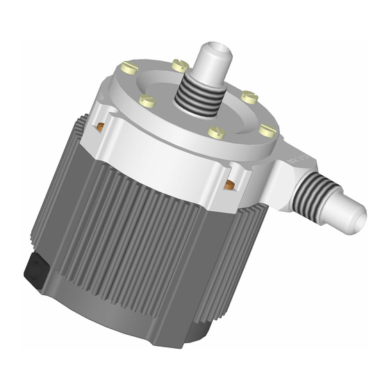
2 Specifications 2.1 System Overview and General Specification Figure 3 shows the mayor components of the BPS-200 pump system. Two basic system configurations are available. The stand-alone configuration (Figure 1), consists of a controller with an integrated user panel to set the speed manually and a reduced PLC for speed setting with an analoge signal. - Page 5 User Manual for BPS-200 www.levitronix.com Figure 3: Pump system BPS-200 with standard components Pos. Component Article Name Article # Characteristics Value / Feature Impeller Pump Casing PTFE ® Sealing Ring Kalrez perfluoroelastomer Fittings Flaretek ½” Max. Diff.-Pressure 2.6 bar / 37.7 psi Pump Head LPP-200.1...
- Page 6 User Manual for BPS-200 www.levitronix.com Pos. Component Article Name Article # Characteristics Value / Feature MCA-1.2-05 (0.5m) 190-10147 Extension MCA-1.2-30 (3m) 190-10092 Adaptor MCA-1.2-50 (5m) 190-10128 Jacket and Connectors FEP-jacket and circular Hummel to D-SUB connector Cable MCA-1.2-70 (7m) 190-10148 MCA-1.2-100 (10m)
-
Page 7: Hydraulic Specifications
User Manual for BPS-200 www.levitronix.com 3 Hydraulic Specifications 3.1.1 Pressure-Flow Curves [gallons/min] Specific gravity = 1 g/cm Viscosity = 0.7 cP 10000 rpm Liquid Temp.: 40C Speed Limit for 24V ≈ 9500 rpm Speed Limit for 48V = 10000 rpm... -
Page 8: Basic Dimensions Of Main Components
User Manual for BPS-200 www.levitronix.com 3.3 Basic Dimensions of Main Components Figure 5: Basic dimensions (in mm and [inch]) of motor BSM-1.x with pump head LPP-200.1 (for other configurations refer to according drawings) PL-4012-00, Rev01, DCO# 09-188... - Page 9 User Manual for BPS-200 www.levitronix.com Alternative for mounting DIN rail clips Figure 6: Basic dimensions (in mm) of controller LPC-200.2 (Same basic dimensions for LPC-200.1) PL-4012-00, Rev01, DCO# 09-188...
-
Page 10: Engineering Information
User Manual for BPS-200 www.levitronix.com 4 Engineering Information 4.1 Sealing and Material Concept Figure 7: Sealing and material concept Item System Materials Component Description Pump casing (lid and bottom) PTFE ® Static sealing O-ring of pump casing Kalrez 6 screws for pump casing... -
Page 11: Power Consumption
User Manual for BPS-200 www.levitronix.com 4.2 Power Consumption [gallons/min] 10000 rpm — Supply = 24 VDC 9000 rpm - - - Supply = 48 VDC 8000 rpm 7000 rpm [Watts] 6000 rpm 5000 rpm Specific gravity = 1 g/cm Viscosity = ~ 0.7 cP Liquid Temp.: 40C... -
Page 12: Thermal Management
User Manual for BPS-200 www.levitronix.com 4.4 Thermal Management 4.4.1 Motor Temperature The motor temperature depends on the ambient and liquid temperature, as well as on the hydraulic operation point. Figure 11, Figure 12 and Figure 14 illustrate the temperature characteristics of the motor depending on these parameters. - Page 13 User Manual for BPS-200 www.levitronix.com [gallons/min] Absolute Temp. Limit — Supply = 24 VDC - - - Supply = 48 VDC Recommended Operational Limit 10000 rpm 9000 rpm 8000 rpm 7000 rpm 6000 rpm Ambient Temp = 25 C Liquid Temp. = 90 C Specific gravity = 1 g/cm3 Viscosity = 0.7 cP...
-
Page 14: Controller Temperature
User Manual for BPS-200 www.levitronix.com ≈ − ⋅ − Figure Figure (Eq. 1) Motor temperatur Liquid temperatur Ambient temperatur Temperatur gradient liquid/mot In order to account for thermal variations (like ambient temperature, closed chemical cabinets or corners without ventilations) and to not significantly reduce the MTBF of the motor it is recommended to keep about... -
Page 15: Installation
User Manual for BPS-200 www.levitronix.com 5 Installation 5.1 Electrical Installation of Controller 5.1.1 Overview The LPC-200 controllers have signal processor controlled power converters with four switched inverters for the drive and the bearing coils of the motor. The signal processor allows precise control of pump speed and impeller position. - Page 16 User Manual for BPS-200 www.levitronix.com Figure 17: Overview of the controller LPC-200.2 for extended operation Interface (as labeled) Description - Position, field and temperature sensor signals from motor “MOTOR” - Drive and bearing currents of the motor - Analog current input: 4 – 20 mA...
-
Page 17: General Installation Instructions
Consult Figure 8 to get the power consumption depending on the flow. Contact Levitronix for consulting and support on the power supply solution. 5. Connect the DC supply wires to the power input connector of the controller. Make sure that the polarity is correct (see Figure 16 and Figure 17) and that AC/DC power supply is off. -
Page 18: Electrical Installation Of Controller Lpc-200.1 For Standalone Operation
User Manual for BPS-200 www.levitronix.com 5.1.3 Electrical Installation of Controller LPC-200.1 for Standalone Operation For standalone operation the LPC-200.1 is disabled when power is turned on. It can be enabled manually by using the “UP” button on the display. However, if the controller shall be enabled automatically, when power is applied the “ENABLE”... -
Page 19: Installation Of Plc Interface For Extended Controller Lpc-200.2
User Manual for BPS-200 www.levitronix.com 5.1.5 Installation of PLC Interface for Extended Controller LPC-200.2 To operate the pump system with a PLC, a minimum set of two digital inputs and one analog input is needed. The digital and analog outputs can be used to monitor the pump status and operating parameters. - Page 20 User Manual for BPS-200 www.levitronix.com Connector Pin Name Designation Levels Note Pin Number Analog In1, (Signal) 4..20 mA = 0..10000 rpm (speed mode) -> Speed Limit = 9000 rpm ≅ 18.4mA Ref Value -> Cut-off (min.) speed = 300 rpm...
-
Page 21: Mechanical Installation Of The Pump/Motor
User Manual for BPS-200 www.levitronix.com 5.2 Mechanical Installation of the Pump/Motor • The motor can be fixed with four screws on the motor bottom (see Figure 5) • As an alternative a the Mounting Base Plate MBP-1.1 (see Table 3 and Table 2) can be used to mount and fix the motor. -
Page 22: Operation
User Manual for BPS-200 www.levitronix.com 6 Operation 6.1 System Operation with LPC-200.1 (Stand-Alone Controller) 6.1.1 State Diagram of LPC-200.1 The controller LPC-200.1 allows stand-alone operation with manual speed setting (“Button Control Mode”) as well as extended operation with analoge speed setting (Analoge Control Mode). Figure 22 shows the state diagram which can be controlled with the manual buttons and the signals on the “USER INTERFACE”... -
Page 23: Standalone Operation (Button Control Mode)
User Manual for BPS-200 www.levitronix.com 6.1.2 Standalone Operation (Button Control Mode) When applying power the system defaults into the “Button Control Mode” and goes into the status “OFF ButtonControl” according to Figure 22. Levitation is disabled and the display indicates “OF”. -
Page 24: Errors Display On The Integrated Panel
User Manual for BPS-200 www.levitronix.com 6.1.4 Errors Display on the Integrated Panel Error Error Code Errors Source on Display Motor No Motor Er 01 Motor Motor cable (power wires) not connected to controller Er 02 Motor Motor cable (sensor wires) not connected to controller... -
Page 25: System Operation With Controller Lpc-200.2 (Plc Version)
User Manual for BPS-200 www.levitronix.com 6.2 System Operation with Controller LPC-200.2 (PLC version) 6.2.1 State Diagram of the PLC Interface Power On Reset: active Status : not active Enable: active Enable: not active Reset: not active ERROR (Speed Control Mode) - Page 26 User Manual for BPS-200 www.levitronix.com State “Off”: The pump system is switched off and the motor has no power. In this state, Levitronix Service Software has full control. State “ON” (speed control mode): The pump system is switched ON and the impeller is rotating with the referenced speed. The motor has electrical power when in this state.
-
Page 27: Inspection And Maintenance
The impeller has a limited lifetime depending on the chemical type, concentration and temperature of the fluid which is pumped. Therefore a preventive periodical exchange of the impeller is recommended. Contact the Levitronix Technical Service Department (see Section 7.2) for further information on replacement times. 7.2 Impeller Replacement Procedure 7.2.1 Preparation... -
Page 28: Instructions For Replacement
2. Unscrew the top of the pump head and remove CAUTION it along with the sealing ring. Use the correct O-Ring type for your process. If necessary, consult the Levitronix Technical Ser- vice Department. Do NOT twist or roll the O-Ring as this may cause leaking to occur. -
Page 29: Troubleshooting
USB interface. The software can be used for performing detailed troubleshooting. For usage of the Service Software refer to the Service Software User Manual (Document #: PL-2034-00), which is available in the ® download section on the Levitronix Web-page or contact the Levitronix Technical Service Department (see under Section 9). -
Page 30: Technical Support
User Manual for BPS-200 www.levitronix.com 9 Technical Support ® For troubleshooting, support and detailed technical information contact Levitronix Technical Service Department: ® Levitronix Technical Service Department Technoparkstr. 1 CH-8005 Zurich Switzerland Phone for US: 888-569 07 18 Phone for outside US:... -
Page 31: Appendix
10.1 Regulatory Status 10.1.1 CE Marking The Bearingless Pump System BPS-200, in his various configurations, is in conformity with the essential requirements of the EMC Directive 2004/108/EC and the Machinery Directive 2006/42/EC. The following particular harmonized standards of the EMC Directive 2004/108/EC are tested and confirmed at a certified laboratory (Hochschule für Technik, Switzerland, Test Laboratory, CH-8005 Zurich, Switzerland, Swiss... -
Page 32: Symbols And Signal Words
User Manual for BPS-200 www.levitronix.com 10.2 Symbols and Signal Words Symbol / Description Type Source Signal Word Indication of an imminently hazardous situation that, if not avoided, will result in death or severe injury. Signal word SEMI S1-0701 DANGER Limited to the most extreme situation...
Need help?
Do you have a question about the BPS-200 and is the answer not in the manual?
Questions and answers