Table of Contents
Advertisement
This manual contains information necessary for the safe and proper use of the BPS-300. Included are
specifications for the standard configurations of the pump system and instructions regarding its use,
installation, operation, adjustment, inspection and maintenance. For special configurations of the pump
system refer to accompanying information. Please familiarize yourself with the contents of the manual to
ensure the safe and effective use of this product. After reading this manual, please store the manual
where the personnel responsible for operating the pump system can readily refer to it at any time.
PL-4006-00, Rev07, DCO# 20-144
BPS-300
2.5 bar
58 liters/min
USER MANUAL
Levitronix
(36.2 psi)
(15.3 gallons/min)
Bearingless Pumps
www.levitronix.com
First Release: 06-Apr-2007
Last Update: 09-Jul-2020
Advertisement
Table of Contents

Related Manuals for Levitronix BPS-300


Summary of Contents for Levitronix BPS-300
- Page 1 (15.3 gallons/min) USER MANUAL This manual contains information necessary for the safe and proper use of the BPS-300. Included are specifications for the standard configurations of the pump system and instructions regarding its use, installation, operation, adjustment, inspection and maintenance. For special configurations of the pump system refer to accompanying information.
-
Page 2: Table Of Contents
User Manual for BPS-300 www.levitronix.com Table of Contents SAFETY PRECAUTIONS ......................... 3 SPECIFICATIONS ............................. 4 System Overview and General Specification ..................4 Pressure-Flow Curves ........................6 General Environmental Conditions ....................6 Basic Dimensions of Main Components .................... 7 ENGINEERING INFORMATION ....................... 9 Sealing and Material Concept...................... -
Page 3: Safety Precautions
1 Safety Precautions The BPS-300 pump system is designed to be used in industrial production machines and equipment containing hydraulic circuits. Typical applications are Semiconductor and chemical manufacturing equipment. Installation shall be done by qualified personnel only. Following safety precautions and all “CAUTION”, “WARNING”... -
Page 4: Specifications
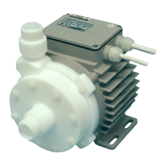
2 Specifications 2.1 System Overview and General Specification Figure 1 and Figure 2 shows the mayor components of the BPS-300 pump system. The standard configuration consists of a controller with an integrated user panel to set the speed manually. Figure 1: Pump system BPS-300 with components... - Page 5 3.8 bar / 55 psi @ 90 C / 194 F liquid temp. Max. Viscosity 50 cP C / 194 Max. Liquid Temp. (for higher liquid temperatures consult with Levitronix) Mechanical Power 300 W ETFE coated Aluminum, Housing waterproofed (IP67 without connectors) Motor LPM-600.2...
-
Page 6: Pressure-Flow Curves
User Manual for BPS-300 www.levitronix.com 2.2 Pressure-Flow Curves [gallons/min] 10.0 12.5 15.0 Specific gravity = 1 g/cm Viscosity = 0.7 cP 8000 rpm [bar] [psi] 7000 rpm 6000 rpm 5000 rpm 4000 rpm [liters/min] Figure 3: Pressure/flow rate chart 2.3 General Environmental Conditions... -
Page 7: Basic Dimensions Of Main Components
User Manual for BPS-300 www.levitronix.com 2.4 Basic Dimensions of Main Components Sensor Figure 4: Basic dimensions (in mm and [inch]) of motor LPM-600.2 with pump head LPP-300.1 PL-4006-00, Rev07, DCO# 20-144... - Page 8 User Manual for BPS-300 www.levitronix.com Cable Cable OD Cable OD Minimum Bending Radius Minimum Bending Radius Jacket Motor Sensor Motor Power Permanent Installation Sometimes Moved 6.60 mm 8.40 mm 7x Cable OD 15 x Cable OD 7.20 mm 11.1 mm...
-
Page 9: Engineering Information
User Manual for BPS-300 www.levitronix.com 3 Engineering Information 3.1 Sealing and Material Concept Figure 6: Sealing and material concept Item System Materials Component Description Pump casing (lid and bottom) PTFE Static sealing O-ring of pump casing Kalrez 8 screws for pump casing... -
Page 10: Power Supply And Consumption
User Manual for BPS-300 www.levitronix.com 3.2 Power Supply and Consumption Figure 7 shows the typical power consumption of the system. If other AC/DC power supplies than the standard specified ones are used, it is recommended to evaluate them under demanding operating situations like fast braking from maximum speed and during power on and take-off of the impeller. -
Page 11: Thermal Management
User Manual for BPS-300 www.levitronix.com 3.4 Thermal Management 3.4.1 Motor Temperature At 25 C (77 F) ambient temperature and liquid temperature < 70 C (158 F) the inside motor temperature is below 75 C (167 F) for all operational points shown in Figure 3. The maximum surface temperature is significantly below this inside temperature. -
Page 12: Installation
User Manual for BPS-300 www.levitronix.com 4 Installation 4.1 Electrical Installation of Controller 4.1.1 Overview The LPC-300.1 controller has signal processor controlled power converters with switched inverters for the drive and the bearing coils of the motor. The signal processor allows precise control of pump speed and impeller position. -
Page 13: Installation Instructions
Figure 7 shows the power consumption depending on the pressure and flow rate. Contact Levitronix for consulting and support on the power supply solution. -
Page 14: Electrical Installation Of Controller Lpc-300.1 For Standalone Operation
User Manual for BPS-300 www.levitronix.com 4.1.3 Electrical Installation of Controller LPC-300.1 for Standalone Operation For standalone operation the controller is disabled when power is turned on. It can be enabled manually by using the “UP” button on the display. If the controller shall be enabled automatically, when power is applied the “ENABLE”... -
Page 15: Mechanical Installation Of The Pump/Motor
User Manual for BPS-300 www.levitronix.com 4.2 Mechanical Installation of the Pump/Motor • The motor can be fixed with four screws on the motor feet (see Figure 4) • As an alternative the motor can be mounted with four screws on the backside (see Figure 4) •... -
Page 16: Operation
User Manual for BPS-300 www.levitronix.com 5 Operation 5.1 State Diagram of LPC-300.1 The controller LPC-300.1 allows stand-alone operation with manual speed setting (“Button Control Mode”) as well as extended operation with analoge speed setting (Analoge Control Mode). Figure 14 shows the state diagram which can be controlled with the manual buttons and the signals on the “USER INTERFACE”... -
Page 17: Standalone Operation (Button Control Mode)
User Manual for BPS-300 www.levitronix.com 5.2 Standalone Operation (Button Control Mode) ▪ When applying power the system defaults into the “Button Control Mode” and goes into the status “OFF ButtonControl” according to Figure 14. Levitation is disabled and the display indicates “OF”. -
Page 18: Error Display On The Integrated Panel
User Manual for BPS-300 www.levitronix.com 5.4 Error Display on the Integrated Panel Error Error Code Errors Source on Display Motor No Motor Er 01 Motor Motor cable (power wires) not connected to controller Er 02 Motor Motor cable (sensor wires) not connected to controller... -
Page 19: Inspection And Maintenance
The impeller has a limited lifetime depending on the chemical type, concentration and temperature of the fluid which is pumped. Therefore, a preventive periodical exchange of the impeller is recommended. Contact the Levitronix Technical Service Department (see Section 8) for further information on replacement times. 6.2 Impeller Replacement Procedure 6.2.1 Preparation... -
Page 20: Instructions For Replacement
2. Unscrew the top of the pump head and remove Use the correct O-Ring type for your process. If it along with the sealing ring. necessary, consult the Levitronix Technical Ser- vice Department. Do NOT twist or roll the O-Ring as this may cause leaking to occur. -
Page 21: Troubleshooting
A digital output on the “USER INTERFACE” connector indicates if the system is active. ▪ However, the source of an error cannot be identified by this signal. ▪ If the problem is still not solved contact the Levitronix Technical Service Department (see Section 8) 8 Technical Support ... -
Page 22: Appendix
9.1 Regulatory Status 9.1.1 CE Marking The Centrifugal Pump System BPS-300, in its various configurations as listed below, is in conformity with the above mentioned European Directives. The pump system is thought to be used in hydraulic circuits of production equipment of the Semiconductor, Chemical and general machinery markets. -
Page 23: Symbols And Signal Words
User Manual for BPS-300 www.levitronix.com 9.2 Symbols and Signal Words Symbol / Description Type Source Signal Word Indication of an imminently hazardous situation that, if DANGER not avoided, will result in death or severe injury. Signal word SEMI S1-0701 Limited to the most extreme situation...
Need help?
Do you have a question about the BPS-300 and is the answer not in the manual?
Questions and answers