Table of Contents
Advertisement
This manual contains information necessary for the safe and proper use of the BPS-200. Included are specifications
for the standard configurations of the pump system and instructions regarding its use, installation, operation,
adjustment, inspection and maintenance. For special configurations of the pump system refer to accompanying
information. If the system must be configured for other parameter settings, then the Levitronix
version V2.0.5.0 or higher (with according manual Levitronix
with the contents of the manual to ensure the safe and effective use of this product. After reading this manual, please
store the manual where the personnel responsible for operating the pump system can readily refer to it at any time.
PL-4012-00, Rev07, DCO# 20-144
BPS-200
2.6 bar
21 liters/min
USER MANUAL
(37.7 psi)
(5.5 gallons/min)
Doc.# PL-4046-00) is necessary. Familiarize yourself
User Manual for BPS-200
www.levitronix.com
®
Service Software
First Release: 03-Oct-2008
Last Update: 09-Jul-2020
Advertisement
Table of Contents

Subscribe to Our Youtube Channel
Related Manuals for Levitronix BPS-200


Summary of Contents for Levitronix BPS-200
- Page 1 (5.5 gallons/min) USER MANUAL This manual contains information necessary for the safe and proper use of the BPS-200. Included are specifications for the standard configurations of the pump system and instructions regarding its use, installation, operation, adjustment, inspection and maintenance. For special configurations of the pump system refer to accompanying ®...
-
Page 2: Table Of Contents
User Manual for BPS-200 www.levitronix.com Table of Contents SAFETY PRECAUTIONS ................................3 SPECIFICATIONS ..................................4 Specification of Components ..............................4 System Overview and General Specification ......................... 6 2.2.1 Stand-Alone System Configuration ........................... 6 2.2.2 Extended System Configuration ............................6 2.2.3 ATEX / IECEx System Configuration .......................... -
Page 3: Safety Precautions
1 Safety Precautions The BPS-200 pump system is designed to be used in industrial production machines and equipment containing hydraulic circuits. Typical applications are Semiconductor and chemical manufacturing equipment. Installation shall be done by qualified personnel only. Following safety precautions and all “CAUTION”, “WARNING”... -
Page 4: Specifications
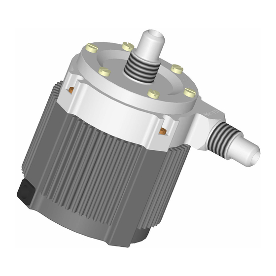
Figure 1 shows the main system components (motor, controller and pump head) together with the system accessories and Figure 2 illustrates the accessories for the pump system. Figure 1: Pump system BPS-200 with standard components Figure 2: Accessories PL-4012-00, Rev07, DCO# 20-144... - Page 5 User Manual for BPS-200 www.levitronix.com System Name Article # Pump Head Motor Controller Note BPS-200.3 / 4 100-90193 / 94 BSM-1.4 LPC-200.1 / 2 Direct cabling between motor and controller. LPP-200.1 BPS-200.1 / 2 100-90191 / 92 BSM-1.3 LPC-200.1 / 2 Adaptor (0.5 - 10m) cables can be ordered according to Table 3.
-
Page 6: System Overview And General Specification
(Speed setting with integrated user panel) 2.2.2 Extended System Configuration The extended version of the BPS-200 pump system (Figure 4) consists of a controller with an extended PLC interface. This allows setting the speed by an external signal and enables precise closed-loop flow or pressure control in connection with either a flow or a pressure sensor. -
Page 7: Atex / Iecex System Configuration
User Manual for BPS-200 www.levitronix.com 2.2.3 ATEX / IECEx System Configuration Together with the standard pump-head and controllers an ATEX / IECEx certified motor allows installation of motor and pump-head within an Ex classified area (see Figure 5). The ATEX / IECEx motor (Pos. 2c in Table 2) comes delivered with special connectors and according extension cables (see Table 3). -
Page 8: Pressure-Flow Curves
User Manual for BPS-200 www.levitronix.com 2.4 Pressure-Flow Curves [gallons/min] Specific gravity = 1 g/cm 10000 rpm Viscosity = 0.7 cP Liquid Temp.: 40C Supply Voltage: 24 V DC Speed Limit for 24V = 9500 rpm Speed Limit for 48V = 10000 rpm... -
Page 9: Basic Dimensions Of Main Components
User Manual for BPS-200 www.levitronix.com 2.6 Basic Dimensions of Main Components Figure 8: Basic dimensions (in mm and [inch]) of motor BSM-1.x with pump head LPP-200.1 (Same dimensions with LPP-200.11. For other configurations refer to according drawings) PL-4012-00, Rev07, DCO# 20-144... - Page 10 User Manual for BPS-200 www.levitronix.com Cable Cable OD Minimum Bending Radius Minimum Bending Radius Jacket Motor Sensor Permanent Installation Sometimes Moved 8.50 mm 7x Cable OD 15 x Cable OD 9.50 mm 5x Cable OD 11 x Cable OD Table 6: Specifications for min. bending radius of motor and adaptor cables for BSM-1...
-
Page 11: Engineering Information
User Manual for BPS-200 www.levitronix.com 3 Engineering Information 3.1 Sealing and Material Concept Figure 10: Sealing and material concept (Motor BSM-1.3 with pump head LPP-200.1. Representative for LPP-200.11) Item System Materials Component Description Pump casing (lid and bottom) PTFE ... -
Page 12: Power Supply And Consumption
User Manual for BPS-200 www.levitronix.com 3.2 Power Supply and Consumption Figure 11 shows the typical power consumption of the system. If other AC/DC power supplies than the standard specified ones are used, it is recommended to evaluate them under demanding operating situations like fast braking from maximum speed and during power on and take-off of the impeller. -
Page 13: Thermal Management
User Manual for BPS-200 www.levitronix.com 3.4 Thermal Management 3.4.1 Motor Temperature The motor temperature depends on the ambient and liquid temperature, as well as on the hydraulic operation point. Figure 14, Figure 15 and Figure 17 illustrate the temperature characteristics of the motor depending on these parameters. - Page 14 User Manual for BPS-200 www.levitronix.com [gallons/min] Absolute Temp. Limit — Supply = 24 VDC - - - Supply = 48 VDC Recommended Operational Limit 10000 rpm 9000 rpm 8000 rpm 7000 rpm 6000 rpm Ambient Temp = 25 C Liquid Temp. = 90 C Specific gravity = 1 g/cm3 Viscosity = 0.7 cP...
-
Page 15: Controller Temperature
User Manual for BPS-200 www.levitronix.com − − Figure Figure (Eq. 1) Motor temperatur Liquid temperatur Ambient temperatur Temperatur gradient liquid/mot All above presented thermal data are typical values, which are partly based on measurements and partly on interpolations with a simplified thermal model and are therefore only guideline values and are suitable for a first layout of the basic thermal concept. -
Page 16: Hydraulic Circuit Design
User Manual for BPS-200 www.levitronix.com 3.5 Hydraulic Circuit Design Following general design rules for the hydraulic circuit shall be considered for a robust operation of the pump system and optimum priming behavior: The general rule for optimum priming behavior is to minimize the pressure drop in the inlet circuit and avoid negative pressure at the inlet of the pump head. -
Page 17: Installation
User Manual for BPS-200 www.levitronix.com 4 Installation 4.1 Electrical Installation of Controller 4.1.1 Overview The LPC-200 controllers have signal processor controlled power converters with switched inverters for the drive and the bearing windings of the motor. The signal processor allows precise control of pump speed and impeller position. - Page 18 User Manual for BPS-200 www.levitronix.com Figure 21: Overview of the controller LPC-200.2 for extended operation Interface (as labeled) Description - Position, field and temperature sensor signals from motor “MOTOR” - Drive and bearing currents of the motor Torque spec. for tightening of connector screws: Min. = 0.4 Nm, Max. = 0.6 Nm - Analog current input: 4 –...
-
Page 19: General Installation Instructions
Consult Figure 11 to get the power consumption depending on the flow. Contact Levitronix for consulting and support on the power supply solution. 5. Connect the DC supply wires to the power input connector of the controller. Make sure that the polarity is correct (see Figure 20 and Figure 21) and that AC/DC power supply is off. -
Page 20: Electrical Installation Of Controller Lpc-200.1 For Standalone Operation
User Manual for BPS-200 www.levitronix.com 4.1.3 Electrical Installation of Controller LPC-200.1 for Standalone Operation For standalone operation the LPC-200.1 is disabled when power is turned on. It can be enabled manually by using the “UP” button on the display. However, if the controller shall be enabled automatically, when power is applied the “ENABLE”... -
Page 21: Electrical Installation Of Controller Lpc-200.2 With Extended Plc
User Manual for BPS-200 www.levitronix.com 4.1.5 Electrical Installation of Controller LPC-200.2 with Extended PLC To operate the pump system with a PLC, a minimum set of two digital inputs and one analog input is needed. The digital and analog outputs can be used to monitor the pump status and operating parameters. - Page 22 Table 11: Signals of the PLC connector for standard firmware Note 1: For other configurations of PLC Inputs and Outputs refer to alternate firmware documentation. ® Note 2: Configurations ca be done with Levitronix Service Software. Note 3: All ground wires have to be connected.
-
Page 23: Mechanical Installation Of The Pump/Motor
User Manual for BPS-200 www.levitronix.com 4.2 Mechanical Installation of the Pump/Motor • The motor can be fixed with four screws on the motor bottom (see Figure 8) • As an alternative the Mounting Base Plate MBP-1.1 (see Table 4) can be used to fix the motor. -
Page 24: Mechanical Installation Of Adaptor/Extension Cables
User Manual for BPS-200 www.levitronix.com 4.5 Mechanical Installation of Adaptor/Extension Cables For connecting the motor to the controller the adaptor cables MCA-1.x shall be used ed (see Table 3 for adaptor cables). For the cables which use an M23 threaded metallic Hummel connector type, check the connection according to the following pictures: ... -
Page 25: Operation
User Manual for BPS-200 www.levitronix.com 5 Operation 5.1 System Operation with LPC-200.1 (Stand-Alone Version) 5.1.1 State Diagram of LPC-200.1 The controller LPC-200.1 allows stand-alone operation with manual speed setting (“Button Control Mode”) as well as extended operation with analog speed setting (“Analog Control Mode”). Figure 29 shows the state diagram which can be controlled with the manual buttons and the signals on the “USER INTERFACE”... -
Page 26: Standalone Operation (Button Control Mode)
User Manual for BPS-200 www.levitronix.com 5.1.2 Standalone Operation (Button Control Mode) ◼ When applying power the system defaults into the “Button Control Mode” and goes into the status “OFF Button Control” according to Figure 29. Levitation is disabled and the display indicates “OF”. -
Page 27: Errors Display On The Integrated Panel
User Manual for BPS-200 www.levitronix.com 5.1.4 Errors Display on the Integrated Panel Error Error Code Errors Source on Display Motor No Motor Er 01 Motor Motor cable (power wires) not connected to controller Er 02 Motor Motor cable (sensor wires) not connected to controller... -
Page 28: System Operation With Controller Lpc-200.2 (Plc Version)
User Manual for BPS-200 www.levitronix.com 5.2 System Operation with Controller LPC-200.2 (PLC version) 5.2.1 State Diagram of the PLC Interface Power On Enable: not active Status : not active Reset: active State 1 Priming: on Enable: active Reset: not active... - Page 29 User Manual for BPS-200 www.levitronix.com State “Off”: ® The pump system is switched off and the motor has no power. In this state, Levitronix Service Software has full control. State “ON” (speed control mode): The pump system is switched ON and the impeller is rotating with the referenced speed. The motor has electrical power when in this state.
-
Page 30: System Operation For Atex / Iecex Applications
The motor ® temperature readings can be monitored via the Levitronix Service Software. For standalone operation with the LPC-200.1 controller the display shall be checked periodically for error messages according to Table 12 (see error Er10 = “Communication problems EEPROM Motor”). -
Page 31: Inspection And Maintenance
The impeller has a limited lifetime depending on the chemical type, concentration and temperature of the fluid which is pumped. Therefore a preventive periodical exchange of the impeller is recommended. Contact the Levitronix Technical Service Department (see Section 8) for further information on replacement times. 6.2 Impeller Replacement Procedure 6.2.1 Preparation... -
Page 32: Instructions For Replacement
User Manual for BPS-200 www.levitronix.com 6.2.2 Instructions for Replacement 1. Power down the pump system and remove the 6. If necessary, remove the existing O-Ring and AC power. If necessary, allow the housing to gently press the new O-Ring into the lid of the cool down to a workable. -
Page 33: Troubleshooting
USB interface. The software can be used for performing detailed troubleshooting. Note: Levitronix Service Software can not be used with the standalone controller LPC-200.1. 8 Technical Support For troubleshooting, support and detailed technical information contact Levitronix Technical Service Department: Levitronix Technical Service Department Technoparkstr. -
Page 34: Appendix
9.1 Regulatory Status 9.1.1 CE Marking The Centrifugal Pump System Family BPS-200, in its configurations as listed below is in conformity with the below mentioned European Directives. The various configurations of the pump system are thought to be used in hydraulic circuits of industrial production equipment of the Semiconductor, Chemical, Life Science (Biotech, Pharmaceuticals) and other machinery markets. -
Page 35: Atex / Iecex Certification And Marking
9.1.5 ATEX / IECEx Certification and Marking Specific motors together with the pump head of the BPS-200 pump system are in conformity with the requirements of the Directive 2014/34/EU and the relevant IECEx standards. The following standards are tested and confirmed at a certified laboratory. -
Page 36: Symbols And Signal Words
User Manual for BPS-200 www.levitronix.com 9.2 Symbols and Signal Words Symbol / Description Type Source Signal Word Indication of an imminently hazardous situation that, if not DANGER Signal word SEMI S1-0701 avoided, will result in death or severe injury. Limited to the...
Need help?
Do you have a question about the BPS-200 and is the answer not in the manual?
Questions and answers