Table of Contents
Advertisement
Quick Links
This manual contains information necessary for the safe and proper use of the BPS-iF100. Included are
specifications for the standard configurations of the flow control system and instructions regarding its use,
installation, operation, adjustment, inspection and maintenance. For special configurations of the flow
control system refer to accompanying information. If the flowmeters must be configured for other
parameter settings, then the Levitronix
Levitronix
Doc.# PL-4047-00) is needed. Familiarize yourself with the contents of the manual to ensure
the safe and effective use of this product. After reading this manual, please store the manual where the
personnel responsible for operating the flow control system can readily refer to it at any time.
PL-4037-00, Rev02, DCO# 21-057
BPS-iF100
Pump Pressure / Flow: 2 bar / 20 l/min
Flow Control Ranges:
4 l/min
USER MANUAL
®
Service Software version V2.0.7.0 (with according manual
8 l/min
20 l/min
User Manual for BPS-iF100
www.levitronix.com
First Release: 16-Jul-2015
Last Update: 12-Mar-2021
Advertisement
Table of Contents

Related Manuals for Levitronix BPS-iF100


Summary of Contents for Levitronix BPS-iF100
- Page 1 20 l/min USER MANUAL This manual contains information necessary for the safe and proper use of the BPS-iF100. Included are specifications for the standard configurations of the flow control system and instructions regarding its use, installation, operation, adjustment, inspection and maintenance. For special configurations of the flow control system refer to accompanying information.
-
Page 2: Table Of Contents
User Manual for BPS-iF100 www.levitronix.com Table of Contents SAFETY PRECAUTIONS ................................3 SPECIFICATIONS ..................................4 Specification of Components ..............................4 System Overview .................................. 6 2.2.1 General System Overview ..............................6 2.2.2 System Configuration for Standard Applications ....................... 7 2.2.3 System Configuration for ATEX / IECEx Applications ....................... 7 General Environmental Conditions ............................ -
Page 3: Safety Precautions
1 Safety Precautions The BPS-iF100 flow control system is designed to be used in industrial production machines and equipment containing hydraulic circuits. Typical applications are Semiconductor and chemical manufacturing equipment. Installation shall be done by qualified personnel only. Following safety precautions and all “CAUTION”, “WARNING”... -
Page 4: Specifications
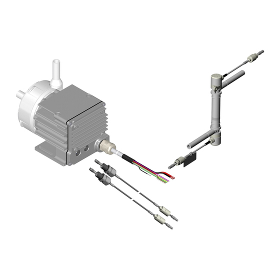
User Manual for BPS-iF100 www.levitronix.com 2 Specifications 2.1 Specification of Components Figure 1 shows the main system components (flow control driver and pump head). Figure 2 shows the standard flow sensors and sensor cables. Figure 3 illustrates the accessories for the flow control system. - Page 5 User Manual for BPS-iF100 www.levitronix.com System Name Article # Flow Sensor Flow Control Driver Pump Head Note BPS-iF100.1-04Z 100-90877 LFS-04-Z (4 l/min) BPS-iF100.1-04U 100-90878 LFS-04-U (4 l/min) IFD-100.1-50-01 BPS-iF100.1-08Z 100-90919 LFS-08-Z (8 l/min) BPS-iF100.1-08U 100-90920 LFS-08-U (8 l/min) (Epoxy, PVC Cable) BPS-iF100.1-20Z...
-
Page 6: System Overview
Various digital inputs and outputs allow controlling and monitoring of the system. A RS485 ® enables communication with a PC with the Levitronix Service Software. Hence parameterization, firmware updates and failure analysis are possible. The RS485 can also be used as a fieldbus to implement more intelligent concepts of flow control. -
Page 7: System Configuration For Standard Applications
User Manual for BPS-iF100 www.levitronix.com 2.2.2 System Configuration for Standard Applications Flow Out Pin Designation User Panel Cable 10: 1: RS485+ 2: RS485- 3: GND 4: NC 5: NC 6: +24VDC AC/DC Power Sensor Supply Adaptor Cable (24VDC, DIN-Rail) PLC Interface:... -
Page 8: General Environmental Conditions
User Manual for BPS-iF100 www.levitronix.com 2.3 General Environmental Conditions Usage Indoor 1 Altitude Up to 2000 m Operating ambient temperature 0 to 40 °C Storage ambient temperature -20 to 80 °C (Extremes for transportation) 15 – 95% (non-condensing) Operating humidity range (relative humidity) Storage humidity range (relative humidity) 15 –... -
Page 9: Pressure-Flow Curves
User Manual for BPS-iF100 www.levitronix.com 2.4 Pressure-Flow Curves [gallons/min] 2.25 Specific gravity = 1 g/cm 9000 rpm Viscosity = 0.7 cP 2.00 Liquid Temp.: 40°C 1.75 8000 rpm 1.50 1.25 [psi] [bar] 1.00 7000 rpm 0.75 6000 rpm 0.50 5000 rpm 0.25... -
Page 10: Flow Control Specifications
PFA for flow sensors and pump head / IP-65 for flow sensor and IP-67 for flow control driver Table 6: Specifications of flow controller systems BPS-iF100 (All data based on water at 20 °C) 1: Values for to the specific hydraulic circuit optimized flow control parameters. -
Page 11: Basic Dimensions Of Main Components
User Manual for BPS-iF100 www.levitronix.com 2.7 Basic Dimensions of Main Components 8 pcs. M3 x 40 Screws (SS PTFE coated, torque spec: 15 Ncm) (For pump head motor mounting. Pump head can be rotated by Tube ½“ 45 degree) „OUT“ Cable „IN“... - Page 12 User Manual for BPS-iF100 www.levitronix.com Mounting Screws: 2x M4x16mm Inox A4 PTFE coated Torque: 50 cNm Note: remove 2 motor screws before mounting WCM-i100.1 NPT 1/8” x 6.7 mm In-/outlet for water cooling fittings. Figure 12: Basic dimensions (in [mm] and [inch]) of water cooling module WCM-i100.1 Note 1: Dimensions are in context with driver IPD-100.1 (representative for IFD-100.1) and pump head LPP-200.7.
- Page 13 User Manual for BPS-iF100 www.levitronix.com U-Shape Z-Shape Tag with Calibration Data Figure 13: Dimension legend for LFS-04 and LFS-08 sensors (left: U-shape, right: Z-shape) U-Shape Z-Shape Tag with Calibration Data Figure 14: Dimension legend for flow sensor LFS-20 (left: U-shape, right: Z-shape)
-
Page 14: Engineering Information
User Manual for BPS-iF100 www.levitronix.com 3 Engineering Information 3.1 Sealing and Material Concept Figure 16: Sealing and material concept (Driver IFD-100.1/2-50 with pump head LPP-200.7) Item System Materials Component Description Pump housing lid and bottom Reinforcing cup PP + GF... -
Page 15: Power Supply And Consumption
User Manual for BPS-iF100 www.levitronix.com 3.2 Power Supply and Consumption 3.2.1 Power Consumption [gallons/min] Specific gravity = 1 g/cm Viscosity = 0.7 cP Liquid Temp.: 40°C 8000 rpm 7000 rpm 6000 rpm 5000 rpm 4000 rpm 10.0 12.5 15.0 17.5 20.0... -
Page 16: Thermal Management
User Manual for BPS-iF100 www.levitronix.com 3.4 Thermal Management The driver temperature depends on the ambient and liquid temperature, as well as on the hydraulic operation point and the cooling method. Figure 18, Figure 19 and Figure 20 illustrate the temperature characteristics of the motor depending on these parameters. - Page 17 User Manual for BPS-iF100 www.levitronix.com [gallons/min] Absolute Temperature Limit 7000 rpm 8000 rpm Recommended Operational 9000 rpm 6000 rpm Temperature Limit [°C] 5000 rpm 4000 rpm [°F] Specific gravity = 1 g/cm Viscosity = 0.7 cP Ambient Temp.: 25°C 10.0 12.5...
-
Page 18: Hydraulic Circuit Design
User Manual for BPS-iF100 www.levitronix.com 3.5 Hydraulic Circuit Design Following general design rules for the hydraulic circuit shall be considered for a robust operation of the pump of the flow control system and optimum priming behavior: 1. The general rule for optimum priming behavior is to minimize the pressure drop in the inlet circuit and avoid negative pressure at the inlet of the pump head. -
Page 19: Installation
Table 11: Signals of the driver cable with designation for standard firmware Note 1: For other configurations of PLC Inputs and Outputs refer to alternate firmware documentation ® Note 2: Configurations can be done with Levitronix Service Software. Note 3: Power wires (P+, P-) have cross section 1.5 mm and all others 0.14 mm... -
Page 20: Overview Electrical Schematics Of Flow Control Driver Interface
User Manual for BPS-iF100 www.levitronix.com 4.1.2 Overview Electrical Schematics of Flow Control Driver Interface Cable Wires (UL Cable) Example of User Levitronix Driver Colours/Designation Interface Circuit Interface Circuit Pink: Digital Input 1 2.2 kW 5..24 V Grey: Digital Input 2 2.2 kW... -
Page 21: Installation Instructions For Power Supply
Figure 17 to get the power consumption depending on the flow. If other power supplies than the ones recommended by Levitronix are used it is highly recommended to test these under dynamic conditions (acceleration and braking of the pump rotor speed). -
Page 22: Installation Of Rs485 Fieldbus Multi Flow Control System Arrays
Technical Service department (see Section 8) for details and support. ® ➔ Address setting of the pump units can be done with the Levitronix Service Software and a PC. A USB/RS485 converter cable with integrated initialization network can be ordered according to Table 4 ®... -
Page 23: Instructions For Electrical Installation Of Flow Sensor
User Manual for BPS-iF100 www.levitronix.com 4.1.7 Instructions for Electrical Installation of Flow Sensor 1. Before connecting a sensor to the driver, the power supply shall be removed. 2. Check if the sensor contains the calibration tag (with K-Factor and Calibration Values) and if the data corresponds to the values on the calibration sheet delivered with each sensor. -
Page 24: Mechanical And Hydraulic Installation Of Flow Sensors
Stable liquid properties should be assured by flushing the circuit with the final liquid until temperature and viscosity becomes stable. After this zero flow shall be realized. Use the ® relevant digital input on the PLC interface (see Table 11) or the Levitronix Service Software to start the Zero Adjust process. -
Page 25: Operation
User Manual for BPS-iF100 www.levitronix.com 5 Operation 5.1 Operation with PLC 5.1.1 State Diagrams Figure 25 and Figure 26 show the state diagram of the integrated pump and the integrated flowmeter. Integrated Pump Power On Status pump: not Enable: active... -
Page 26: State Description Of Integrated Pump Controller
5.1.2 State Description of Integrated Pump Controller Pump State “Off”: ® The pump system is switched off and the impeller is not levitated. In this state, Levitronix Service Software has full control. Pump State “Flow Control Mode”: The pump system is switched ON and the impeller is rotating with the referenced flow. -
Page 27: State Of Integrated Flow Controller
User Manual for BPS-iF100 www.levitronix.com 5.1.4 State of Integrated Flow Controller The status of the integrated flow controller can be determined from both, status of integrated pump and status of integrated flowmeter and is summarized in Table 13 with the most important state combinations, state description and possible corrective actions. -
Page 28: Operation For Atex / Iecex Application
User Manual for BPS-iF100 www.levitronix.com 5.3 Operation for ATEX / IECEx Application Specific precautions may be considered while using the pump system in potential explosive gas atmospheres according to ATEX / IECEx category 3G/3D (Zone 2 and 22). The user shall prevent priming issues during normal pump operation. Especially precautions have to be considered during installing and maintenance operations to prevent the occurrence of combustible atmospheres. -
Page 29: Inspection And Maintenance
User Manual for BPS-iF100 www.levitronix.com 6 Inspection and Maintenance 6.1 Replacement Interval of the Impeller The impeller has a limited lifetime depending on the chemical type, concentration and temperature of the fluid which is pumped. Therefore, a preventive periodical exchange of the impeller is recommended. Contact ®... -
Page 30: Instructions For Replacement
User Manual for BPS-iF100 www.levitronix.com 6.2.2 Instructions for Replacement 1. Power down the pump system and remove the 6. If necessary, remove the existing O-Ring and AC power. If necessary, allow the housing to gently press the new O-Ring into the lid of the cool down to a workable temperature. -
Page 31: Troubleshooting
7.3 Troubleshooting with User Panel LUI-B.1 For troubleshooting and failure analysis with the user panel LUI-B.1 the integrated display gives advice about status and potential failure details. 8 Technical Support For troubleshooting, support and detailed technical information contact Levitronix Technical Service Department: Levitronix Technical Service Department Technoparkstr. -
Page 32: Appendix
9 Appendix 9.1 Regulatory Status 9.1.1 CE Marking We herewith declare that the Flow Control System Family BPS-iF100, in its various configurations, is in conformity with the below mentioned European Directives. Machinery Directive 2006/42/EC: The machinery directive essentially has been followed by a risk analysis, according mitigation actions and a user manual for safe operation. -
Page 33: Symbols And Signal Words
User Manual for BPS-iF100 www.levitronix.com 9.2 Symbols and Signal Words Symbol / Description Type Source Signal Word Indication of an imminently hazardous situation that, if not DANGER Signal word SEMI S1-0701 avoided, will result in death or severe injury. Limited to the...
Need help?
Do you have a question about the BPS-iF100 and is the answer not in the manual?
Questions and answers