Table of Contents
Advertisement
This manual contains information necessary for the safe and proper use of the BPS-i600. Included are specifications
for the standard configurations of the pump system and instructions regarding its use, installation, operation,
adjustment, inspection and maintenance. For special configurations of the pump system refer to accompanying
information. If the system must be configured for other parameter settings, then the Levitronix
version V2.0.5.0 or higher (with according manual Levitronix
with the contents of the manual to ensure the safe and effective use of this product. After reading this manual, please
store the manual where the personnel responsible for operating the pump system can readily refer to it at any time.
PL-4089-00, Rev00, DCO# 21-271
BPS-i600
3.1 bar
75 liters/min
USER MANUAL
(45 psi)
(20 gallons/min)
Doc.# PL-4043-00) is necessary. Familiarize yourself
User Manual for BPS-i600
www.levitronix.com
®
Service Software
First Release: 14-Dec-2019
Last Update: 03-Dec-2021
Advertisement
Table of Contents

Subscribe to Our Youtube Channel
Related Manuals for Levitronix BPS-i600


Summary of Contents for Levitronix BPS-i600
- Page 1 (20 gallons/min) USER MANUAL This manual contains information necessary for the safe and proper use of the BPS-i600. Included are specifications for the standard configurations of the pump system and instructions regarding its use, installation, operation, adjustment, inspection and maintenance. For special configurations of the pump system refer to accompanying ®...
-
Page 2: Table Of Contents
User Manual for BPS-i600 www.levitronix.com Table of Contents SAFETY PRECAUTIONS ................................3 SPECIFICATIONS ..................................4 Specification of Components ..............................4 System Overview and General Specification ......................... 6 2.2.1 Standard System Configuration for Speed Control ......................6 2.2.2 Standard Configuration for Process Control ........................6 General Environmental Conditions ............................ -
Page 3: Safety Precautions
1 Safety Precautions The BPS-i600 pump system is designed to be used in industrial production machines and equipment containing hydraulic circuits. Typical applications are semiconductor and chemical manufacturing equipment. Installation shall be done by qualified personnel only. Following safety precautions and all “CAUTION”, “WARNING”... -
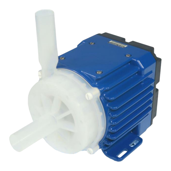
Page 4: Specifications
User Manual for BPS-i600 www.levitronix.com 2 Specifications 2.1 Specification of Components Figure 1: Pump system with main standard components Figure 2: Accessories PL-4089-00, Rev00, DCO# 21-271... - Page 5 User Manual for BPS-i600 www.levitronix.com System Name Article # Pump Head Driver Note BPS-i600.1 100-91405 LPP-600.29 IPD-600.1-50-01 PFA pump head, Epoxy coated motor, 5 m PVC cable with open wires BPS-i600.2 100-91406 LPP-600.29 IPD-600.2-50-01 PFA pump head, ETFE coated motor, 5 m FEP cable with open wires Table 1: Standard system configurations Pos.
-
Page 6: System Overview And General Specification
Various digital inputs and outputs allow controlling and monitoring of the system. A RS485 enables ® communication with a PC with the Levitronix Service Software. Hence parameterization, firmware updates and diagnostics are possible. The RS485 can also be used as a fieldbus to implement more intelligent concepts of pump control. -
Page 7: General Environmental Conditions
User Manual for BPS-i600 www.levitronix.com 2.3 General Environmental Conditions Usage Indoor Altitude Up to 2000 m Operating ambient temperature 0 to 40 °C Storage ambient temperature -20 to 80 °C (Extremes for transportation) 15 – 95% (non-condensing) Operating humidity range (relative humidity) Storage humidity range (relative humidity) 15 –... -
Page 8: Pressure-Flow Curves
User Manual for BPS-i600 www.levitronix.com 2.4 Pressure-Flow Curves [gallons / min] 10.0 15.0 20.0 Specific gravity = 1 g/cm Viscosity = 0.7 cP Liquid Temp.: 40 °C DC-Voltage = 48 V 9000 rpm Pump Head: LPP-600.29 8000 rpm [bar] [psi]... -
Page 9: Basic Dimensions Of Main Components
User Manual for BPS-i600 www.levitronix.com 2.6 Basic Dimensions of Main Components Tube 1“ Cable outer diameter (OD): < 8.8 mm Standard length: 5m, open wires Power Supply Connection: 2 wires a 1.5 mm each connected to one ferrule 4pcs M6x25 Screws (SS PTFE coated, torque spec: 50 Ncm) (For pump head motor mounting. - Page 10 User Manual for BPS-i600 www.levitronix.com Mounting Screws: 4x M4x16mm Inox A4 PTFE coated Torque: 60 cNM Remove 4 motor screws before mounting WCM-i600. NPT 1/8” x 6.9 mm In-/outlet for water cooling fittings. Figure 8: Basic dimensions (in [mm] and [inch]) of water cooling module WCM-i600.1 in context with of driver IPD-600.x...
-
Page 11: Engineering Information
User Manual for BPS-i600 www.levitronix.com 3 Engineering Information 3.1 Sealing and Material Concept Figure 9: Sealing and material concept (Driver IPD-600.1/2-50 with pump head LPP-600.29) Item System Materials Component Description Pump housing lid and bottom (wet part) Impeller LPI-600.2 Pump head LPP-600.29... -
Page 12: Power Supply And Consumption
If 65 °C is exceeded, a warning is given within the driver announcing to the user that the driver is running near ® the thermal limit (see explanation in Section 3.4). The warning signal can be monitored with the Levitronix Service Software or configured on one of the digital outputs. -
Page 13: Thermal Management
User Manual for BPS-i600 www.levitronix.com 3.4 Thermal Management The driver temperature depends on the ambient and liquid temperature, as well as on the hydraulic operation point. Figure 11, Figure 12 illustrate the temperature characteristics of the motor depending on these parameters. - Page 14 User Manual for BPS-i600 www.levitronix.com [gallons / min] 10.0 15.0 20.0 Absolute Thermal Limit Recommended Operational Temperature Limit 9000 rpm 8000 rpm 7000 rpm 6000 rpm [°C] 5000 rpm [°F] Ambient Temp = 25 °C Liquid Temp. = 90° C Specific gravity = 1 g/cm Viscosity = 0.7 cP...
-
Page 15: Hydraulic Circuit Design
User Manual for BPS-i600 www.levitronix.com 3.5 Hydraulic Circuit Design Following general design rules for the hydraulic circuit shall be considered for a robust operation of the pump system and optimum priming behavior: 1. The general rule for optimum priming behavior is to minimize the pressure drop in the inlet circuit and avoid negative pressure at the inlet of the pump head. -
Page 16: Installation
Table 7: Signals of the driver cable with designation for standard firmware Note 1: For other configurations of PLC Inputs and Outputs refer to alternate firmware documentation ® Note 2: Configurations can be done with Levitronix Service Software. Note 3: Power wires (P+, P-) are two wires (a 1.5 mm ) connected to one with total cross section 3 mm , all others 0.14 mm... -
Page 17: Overview Electrical Schematics Of Driver Interface
User Manual for BPS-i600 www.levitronix.com 4.1.2 Overview Electrical Schematics of Driver Interface Cable Wires Example of User Levitronix Driver Colours/Designation Interface Circuit Interface Circuit Pink: Digital Input 1 2.2 kW 5..24 V Grey: Digital Input 2 2.2 kW Yellow: Common Digital Input... -
Page 18: Installation Instructions For Power Supply
For usage of the RS485 as a control or service interface, an initialization resistor network according to Figure 15 or Figure 16 shall be used in order to have a stable communication and avoid disturbance effects. The ® RS485 protocol for master communication is available at Levitronix on request. ®... -
Page 19: Installation Of Rs485 Fieldbus Multi-Pump System Arrays
WARNING BPS-i600 pump drivers are not rated to be placed next to flammable gases. Do not use the driver next to flammable gases. 4.2.2 Mechanical Installation of Water Cooling Module The water cooling module WCM-600.1 can be mounted to the driver top as illustrated in Figure 8. -
Page 20: Operation
User Manual for BPS-i600 www.levitronix.com 5 Operation Power On Enable: Status : not active not active State 1 Reset: Pulse 300-700 ms Priming: on Enable: active Priming: off Enable: not active Enable: active ERROR (Priming Mode) (Speed Control Mode) Timeout,... - Page 21 User Manual for BPS-i600 www.levitronix.com State “Off”: ® The pump system is switched off and the motor has no power. In this state, Levitronix Service Software has full control. State “ON” (speed control mode): The pump system is switched ON and the impeller is rotating with the referenced speed. The motor has electrical power when in this state.
-
Page 22: Inspection And Maintenance
User Manual for BPS-i600 www.levitronix.com 6 Inspection and Maintenance 6.1 Replacement Interval of the Pump Head The impeller has a limited lifetime depending on the chemical type, concentration and temperature of the fluid which is pumped. Therefore, a preventive periodical exchange of the pump head is recommended. Contact ®... -
Page 23: Troubleshooting
Service Software allows communication with the pump system in connection with a PC and a USB interface. The USB to RS485 adaptor cable as specified in Table 3 can be used to setup communication. The software can be used for performing detailed troubleshooting. The Levitronix Service Software is ... -
Page 24: Appendix
9 Appendix 9.1 Regulatory Status 9.1.1 CE Marking We herewith declare that the Centrifugal Pump System Family BPS-i600, in its various configurations, is in conformity with the below mentioned European Directives. Machinery Directive 2006/42/EC: The machinery directive essentially has been followed by a risk analysis, according mitigation actions and a user manual for safe operation. -
Page 25: Symbols And Signal Words
User Manual for BPS-i600 www.levitronix.com 9.2 Symbols and Signal Words Symbol / Description Type Source Signal Word Indication of an imminently hazardous situation that, if not DANGER Signal word SEMI S1-0701 avoided, will result in death or severe injury. Limited to the...
Need help?
Do you have a question about the BPS-i600 and is the answer not in the manual?
Questions and answers