Table of Contents
Advertisement
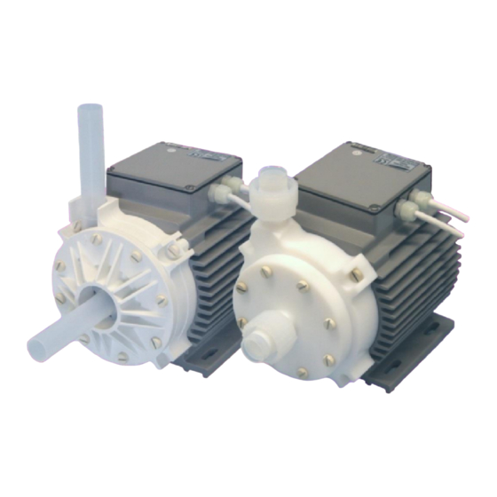
High Pressure Profile:
High Flow Profile:
This manual contains information necessary for the safe and proper use of the BPS-2000. Included are
specifications for the standard configurations of the pump system and instructions regarding its use,
installation, operation, adjustment, inspection and maintenance. For special configurations of the pump
system refer to accompanying information. Please familiarize yourself with the contents of the manual to
ensure the safe and effective use of this product. After reading this manual, please store the manual
where the personnel responsible for operating the pump system can readily refer to it at any time.
PL-4021-00, Rev03, DCO# 15-235
BPS-2000
6.9 bar
80 liters/min
4.2 bar
140 liters/min
USER MANUAL
User Manual for BPS-2000
www.levitronix.com
(100 psi)
(21 gallons/min)
(61 psi)
(37 gallons/min)
Advertisement
Table of Contents

Subscribe to Our Youtube Channel
Related Manuals for Levitronix BPS-2000.1


Summary of Contents for Levitronix BPS-2000.1
- Page 1 User Manual for BPS-2000 www.levitronix.com BPS-2000 High Pressure Profile: 6.9 bar (100 psi) 80 liters/min (21 gallons/min) High Flow Profile: 4.2 bar (61 psi) 140 liters/min (37 gallons/min) USER MANUAL This manual contains information necessary for the safe and proper use of the BPS-2000. Included are specifications for the standard configurations of the pump system and instructions regarding its use, installation, operation, adjustment, inspection and maintenance.
-
Page 2: Table Of Contents
User Manual for BPS-2000 www.levitronix.com Table of Content SAFETY PRECAUTIONS ................................3 SPECIFICATIONS..................................4 Specification of Components ..............................4 Standard System Configurations ............................6 2.2.1 Standalone System Configuration ..................................6 2.2.2 Extended System Configuration ..................................6 2.2.3 ATEX / IECEx System Configuration ................................. 7 General Environmental Conditions ............................ -
Page 3: Safety Precautions
Installation shall be done by qualified personnel only. Following safety precautions and all “CAUTION”, “WARNING” and “DANGER” indications in the relevant sections shall be followed. CAUTION ® Do not under any circumstances open the controller or motor. Levitronix does not assume responsibility for any damage, which occurs under such circumstances. CAUTION High magnetic field strength of pump impeller. -
Page 4: Specifications
User Manual for BPS-2000 www.levitronix.com 2 Specifications 2.1 Specification of Components Figure 1 shows the main system components (motor, controllers, and pump head) and Figure 2 illustrates the accessories. Figure 1: Pump system with standard components „High Pressure“ „High Flow“... - Page 5 User Manual for BPS-2000 www.levitronix.com Standard System Name Article # Pump Head Controller Motor Note Firmware BPS-2000.1 100-90479 LPP-2000.6 (High Flow) LPC-2000.1-01 E1.25 Adaptor/Extension (0.5 - 10m) cables according to Table 3 (position 4a BPS-2000.2 100-90480 LPP-2000.6 (High Flow) LPC-2000.2-01 E1.48...
-
Page 6: Standard System Configurations
A USB ® interface allows communication with a PC in connection with the Levitronix Service Software. Hence parameterization, firmware updates and failure analysis are possible. -
Page 7: Atex / Iecex System Configuration
User Manual for BPS-2000 www.levitronix.com 2.2.3 ATEX / IECEx System Configuration Together with the standard pump head and controllers an ATEX / IECEx certified motor allows installation of motor and pump head within an Ex classified area (see Figure 5). The ATEX / IECEx motor (Pos. 2b in in Table 2) comes delivered with special connectors and according extension cables (Pos. -
Page 8: Pressure-Flow Curves
User Manual for BPS-2000 www.levitronix.com 2.4 Pressure-Flow Curves [gpm] Specific gravity = 1 g/cm Standard Limit: Viscosity = 0.7 cP Speed Limit = 8000 rpm Liquid Temp.: 40 C Limits for 90 C Liquid: Limits due to caviation 8000 rpm... -
Page 9: Npshr Curves
User Manual for BPS-2000 www.levitronix.com 2.5 NPSHr Curves [gpm] Specific gravity = 1 g/cm Viscosity = 0.7 cP 6000 rpm Liquid Temp.: 40 C 5000 rpm 8000 rpm [bar] 7000 rpm NPSHr Criteria: Minimum absolute inlet pressure where the pump pressure is reduced to 3% [lpm] Figure 8: NPSHr curves for “High Flow”... -
Page 10: Maximum Static Pressure For Pump Heads
User Manual for BPS-2000 www.levitronix.com 2.6 Maximum Static Pressure for Pump Heads [°F] Safety Factor = 1.3 (according to EN12162) Limitation: Given by deformation. Burst pressure is significantly higher. Ambient Temp = 25 C Note: Pressure limit only valid for pumphead mounted on motor... -
Page 11: Basic Dimensions Of Main Components
User Manual for BPS-2000 www.levitronix.com 2.7 Basic Dimensions of Main Components Spec. Pump Head Screws: Spec. Pump Motor Screws: Dimensions: 8x M8x40 Dimensions: 4x M8x30 Material: Stainless Steel PTFE Coated Material: Stainless Steel PTFE Coated Torque Spec.: 60 Ncm Torque Spec.: 60 Ncm Inlet/Outlet Fitting: 1“... - Page 12 User Manual for BPS-2000 www.levitronix.com Spec. Pump Head Screws: Dimensions: 8x M8x40 Material: SS PTFE Coated Spec. Pump Motor Screws: Torque Spec.: 60 Ncm Dimensions: 4x M8x30 Material: SS PTFE Coated Torque Spec.: 60 Ncm Inlet/Outlet Fitting: 1“ Pillar Super 300 Figure 12: Basic dimensions (in mm and [inch]) of LPM-2000 motor with LPP-2000.7 pump head (High-Pressure)
- Page 13 User Manual for BPS-2000 www.levitronix.com Air Connection Port: NPT ¼“ with max. depth = 14mm Figure 13: Basic dimensions (in mm and [inch]) Motor LPM-2000 with Air Cooling Module ACM-4.2 (Same basic dimensions for ACM-4.3) Cable Cable OD Cable OD...
-
Page 14: Engineering Information
User Manual for BPS-2000 www.levitronix.com 3 Engineering Information 3.1 Sealing and Material Concept Figure 15: Sealing and material concept for “High Flow” system (LPM-2000.2 with pump head LPP-2000.6) Item System Materials Component Description Pump casing (lid and bottom, 1” tube fitting) - Page 15 User Manual for BPS-2000 www.levitronix.com Figure 16: Sealing and material concept for “High Pressure” system (LPM-2000.2 motor with pump head LPP-2000.7) Item System Materials Component Description Pump casing (lid and bottom, 1” Pillar Super 300 PTFE Fittings Female) ® Static sealing O-ring of pump housing...
-
Page 16: Ac Supply And Power Consumption
User Manual for BPS-2000 www.levitronix.com 3.2 AC Supply and Power Consumption 3.2.1 Power Consumption [gpm] 2000 Specific gravity = 1 g/cm 1800 Viscosity = ~ 0.7 cP Liquid Temp.: 40 1600 8000 rpm 1400 1200 [Watts] 1000 7000 rpm 6000 rpm... -
Page 17: Ac Input Voltage And Grid Currents
User Manual for BPS-2000 www.levitronix.com 3.2.2 AC Input Voltage and Grid Currents The input grid currents depend on the power and the input voltage. As shown in Table 9 maximum input grid currents are achieved at highest power and lowest voltage. -
Page 18: Temperature Monitoring
User Manual for BPS-2000 www.levitronix.com 3.3 Temperature Monitoring To avoid overheating of the system, the controller and motor temperatures are monitored. If the controller temperature exceeds 70°C (158°F) or the motor temperature exceeds 90°C (194°F) for a duration of more than 10 minutes, the system goes into an error state and the pump stops. -
Page 19: Thermal Management
User Manual for BPS-2000 www.levitronix.com 3.4 Thermal Management 3.4.1 Motor Temperature The motor temperature depends on the ambient and liquid temperature, as well as on the hydraulic operation point and the characteristics (viscosity and density) of the liquid. Figure 21 illustrates the temperature characteristics for aqueous liquids at room temperature. - Page 20 User Manual for BPS-2000 www.levitronix.com [gpm] Absolute Temperature Limit Ambient Temp = 25 C Liquid Temp. = 40 C Specific gravity = 1 g/cm3 Viscosity = 0.7 cP Recommended Operational Limit Air cooling with ACM-4.2 1 bar, ~25 C air 8000 rpm [°F]...
- Page 21 User Manual for BPS-2000 www.levitronix.com [°F] No Active Cooling: Temp. Gradient = 0.49 [°F] Ambient Temp = 25 C Specific gravity = 1 g/cm3 Active Cooling with ACM-4.2: Viscosity = 0.7 cP Cooling Pressure = 1 bar Temp. Gradient = 0.29...
-
Page 22: Controller Temperature
User Manual for BPS-2000 www.levitronix.com 3.4.2 Controller Temperature Depending on the ambient temperature and the placement of the controller additional cooling may be required (see Figure 24). To improve cooling of the controller, place the device into a moving air stream. If the controller is mounted in a compact area or adjacent to additional heat sources (e.g. -
Page 23: Hydraulic Circuit Design
Figure 25: Avoidance of stress forces and torques at the inlet and outlet of the pump head ® Contact the Levitronix Technical Service department (see Section 8) for more detailed considerations and support on the design of the hydraulic circuit. -
Page 24: Installation
User Manual for BPS-2000 www.levitronix.com 4 Installation 4.1 Electrical Installation of Controller 4.1.1 Overview The LPC-2000 controllers have signal processor controlled power converters with switched inverters for the drive and the bearing windings of the motor. The signal processor allows precise control of pump speed and impeller position. - Page 25 User Manual for BPS-2000 www.levitronix.com Figure 27: Overview of the controller LPC-2000.2-xx for extended operation Interface (as labeled) Description Position, field and temperature sensor signals from motor. “SENSORIC” Torque spec. for tightening of connector screws on motor side: Min. = 0.4 Nm, Max. = 0.6 Nm - Analog current input: 4 –...
-
Page 26: General Installation Instructions
User Manual for BPS-2000 www.levitronix.com 4.1.2 General Installation Instructions WARNING Hazardous voltage may be present. Always isolate the electrical power supply before making or changing connections to the unit. To remove the power it is recommended to use an isolating device. -
Page 27: Electrical Installation Of Controller Lpc-2000.1 For Standalone Operation
User Manual for BPS-2000 www.levitronix.com 4.1.3 Electrical Installation of Controller LPC-2000.1 for Standalone Operation For standalone operation the LPC-2000.1 is disabled when power is turned on. It can be enabled manually by using the “UP” button on the display. If the controller shall be enabled automatically, when power is applied the “ENABLE”... -
Page 28: Installation Of Plc Interface For Extended Controller Lpc-2000.2
User Manual for BPS-2000 www.levitronix.com 4.1.5 Installation of PLC Interface for Extended Controller LPC-2000.2 To operate the pump system with a PLC, a minimum set of two digital inputs and one analog input is needed. The digital and analog outputs can be used to monitor the pump status and operating parameters. - Page 29 User Manual for BPS-2000 www.levitronix.com Connector Wire name Designation Levels Note 4..20 mA = 0..10000 rpm (speed mode) Analog In1, (Signal) 8000 rpm = 16.8 mArms for “High Flow” Ref Value 10000 rpm = 20 mArms for “High Pressure” (Current Input) - Grounds are internally connected.
-
Page 30: Mechanical Installation Of The Pump/Motor
User Manual for BPS-2000 www.levitronix.com 4.2 Mechanical Installation of the Pump/Motor 4.2.1 Standard Installation Instructions and Information WARNING Overheating of the Motor Power and Extension Power Cable To prevent an overheating of the motor power and extension power cables, do not roll-up or install several motor power cables in the same cable channel. - Page 31 User Manual for BPS-2000 www.levitronix.com A protective earth wire (minimum Wire Gauge AWG14, copper diameter 1.63mm, cross section 2.08mm shall be attached to the ATEX / IECEx specific motors by following the instructions outlined below. 1) Motors used without cooling module ACM-4.3 A protective earth wire shall be attached to the ATEX / IECEx specific motor housing by using one of the eight M4 threads on the backside of the motor.
-
Page 32: Mechanical Installation Of The Controller
If explosive flammable gases are present, place the controller in an explosion-proof cabinet. CAUTION ® Do not under any circumstances open the controller. Levitronix does not assume responsibility for any damage, which occurs under such circumstances. 4.4 Mechanical Installation of Adaptor/Extension Cables For connecting the motor to the controller the adaptor cables MCAP-2000.x (for power cable) and MCAS-... -
Page 33: Operation
User Manual for BPS-2000 www.levitronix.com 5 Operation 5.1 System Operation with LPC-2000.1 (Standalone Version) 5.1.1 State Diagram of LPC-2000.1 The controller LPC-2000.1 allows standalone operation with manual speed setting (“Button Control Mode”) as well as extended operation with analog speed setting (Analog Control Mode). Figure 37 shows the state diagram which can be controlled with the manual buttons and the signals on the “USER INTERFACE”... -
Page 34: Standalone Operation (Button Control Mode)
User Manual for BPS-2000 www.levitronix.com 5.1.2 Standalone Operation (Button Control Mode) When applying power the system defaults into the “Button Control Mode” and goes into the status “OFF ButtonControl” according to Figure 37. Levitation is disabled and the display indicates “OF”. -
Page 35: Extended Operation ("Analog Control Mode")
User Manual for BPS-2000 www.levitronix.com 5.1.3 Extended Operation (“Analog Control Mode”) In order to be able to control the pump with external signals (PLC) the mode “Analog Control Mode” has to be set with the display buttons. The “UP” and “Down” buttons have to be pressed simultaneously during 5 seconds. -
Page 36: System Operation With Controller Lpc-2000.2 (Plc Version)
User Manual for BPS-2000 www.levitronix.com 5.2 System Operation with Controller LPC-2000.2 (PLC version) 5.2.1 State Diagram of the PLC Interface Power On Enable: not active Reset: active Status : not active State 1 Priming: on Enable: active Reset: not active... - Page 37 User Manual for BPS-2000 www.levitronix.com State “Off”: The pump system is switched off and the motor has no power. In this state, Levitronix Service Software has full control. State “ON” (speed control mode): The pump system is switched ON and the impeller is rotating with the referenced speed. The motor has electrical power when in this state.
-
Page 38: System Operation For Atex / Iecex Applications
User Manual for BPS-2000 www.levitronix.com 5.3 System Operation for ATEX / IECEx Applications 5.3.1 General Safety Requirements Specific precautions may be considered while using the pump system in potential explosive gas atmospheres according to ATEX / IECEx category 3G/3D (Zone 2 and 22). -
Page 39: Inspection And Maintenance
The impeller has a limited lifetime depending on the chemical type, concentration and temperature of the fluid which is pumped. Therefore a preventive periodical exchange of the impeller is recommended. Contact the Levitronix Technical Service Department (see Section 8) for further information on replacement times. 6.2 Impeller Replacement Procedure 6.2.1 Preparation... -
Page 40: Instructions For Replacement With Ptfe Pump Housing
2. Unscrew the lid of the pump head and remove it along with the sealing ring. Use the correct O-Ring type for your process. If ® necessary, consult the Levitronix Technical Service Department. Do NOT twist or roll the O-Ring as this may cause leaking to occur. -
Page 41: Instructions For Replacement With Pfa+Pp Pump Housing
CAUTION along with the sealing ring. Use the correct O-Ring type for your process. If ® necessary, consult the Levitronix Technical Service Department. Do NOT twist or roll the O-Ring as this may cause leaking to occur. 7. Align the PFA lid with the PP lid of the... - Page 42 User Manual for BPS-2000 www.levitronix.com 8. Press the lid with the O-ring flush into the 10. Carefully tighten the 8 pump housing screws bottom of the pump casing. by following two times the sequence in the figure below with increasing torque after each sequence.
-
Page 43: Troubleshooting
Section 8). Note: the Levitronix Service Software can not be used with the standalone controller LPC-2000.1. 8 Technical Support For troubleshooting, support and detailed technical information contact Levitronix Technical Service Department: Levitronix Technical Service Department Technoparkstr. 1... -
Page 44: Appendix
User Manual for BPS-2000 www.levitronix.com 9 Appendix 9.1 Regulatory Status 9.1.1 CE Marking The Centrifugal Pump System BPS-2000, in its various configurations, is in conformity with the below mentioned European Directives. The pump system is thought to be used in hydraulic circuits of production equipment of the Semiconductor, Chemical and general machinery applications. -
Page 45: Atex / Iecex Marking
9.1.5 Immunity to Voltage Sags – Semi F47 ® Based on internally testing at Levitronix the pump system BPS-2000 in its various configurations is able to handle all the voltage sags defined in SEMI F47. Therefore the pump system BPS-2000 full fills the requirements of the SEMI F47 standard. -
Page 46: Symbols And Signal Words
User Manual for BPS-2000 www.levitronix.com 9.2 Symbols and Signal Words Symbol / Description Type Source Signal Word Indication of an imminently hazardous situation that, if DANGER not avoided, will result in death or severe injury. Signal word SEMI S1-0701 Limited to the most extreme situation...
Need help?
Do you have a question about the BPS-2000.1 and is the answer not in the manual?
Questions and answers