Table of Contents
Advertisement
This manual contains information necessary for the safe and proper use of the BPS-4000. Included are
specifications for the standard configurations of the pump system and instructions regarding its use,
installation, operation, adjustment, inspection and maintenance. For special configurations of the pump
system refer to accompanying information. Please familiarize yourself with the contents of the manual to
ensure the safe and effective use of this product. After reading this manual, please store the manual
where the personnel responsible for operating the pump system can readily refer to it at any time.
PL-4016-00, Rev11, DCO# 18-057
BPS-4000
6.3 bar
280 liters/min
USER MANUAL
(91 psi)
(74 gallons/min)
User Manual for BPS-4000
www.levitronix.com
First Release: 07-Jul-09
Last Update: 16-May-18
Advertisement
Table of Contents

Subscribe to Our Youtube Channel
Related Manuals for Levitronix BPS-4000


Summary of Contents for Levitronix BPS-4000
- Page 1 (74 gallons/min) USER MANUAL This manual contains information necessary for the safe and proper use of the BPS-4000. Included are specifications for the standard configurations of the pump system and instructions regarding its use, installation, operation, adjustment, inspection and maintenance. For special configurations of the pump system refer to accompanying information.
-
Page 2: Table Of Contents
User Manual for BPS-4000 www.levitronix.com Table of Contents SAFETY PRECAUTIONS..................................3 SPECIFICATIONS ....................................4 Specification of Components .................................4 Standard System Configurations ..............................6 2.2.1 Stand-Alone System Configuration..................................6 2.2.2 Extended System Configuration ..................................6 2.2.3 ATEX / IECEx System Configuration ................................. 7 2.2.4 Hazardous Location Cl1 Div2 System Configuration ............................ -
Page 3: Safety Precautions
1 Safety Precautions The BPS-4000 pump system is designed to be used in industrial production machines and equipment containing hydraulic circuits. Typical applications are Semiconductor and chemical manufacturing equipment. Installation shall be done by qualified personnel only. Following safety precautions and all “CAUTION”, “WARNING”... -
Page 4: Specifications
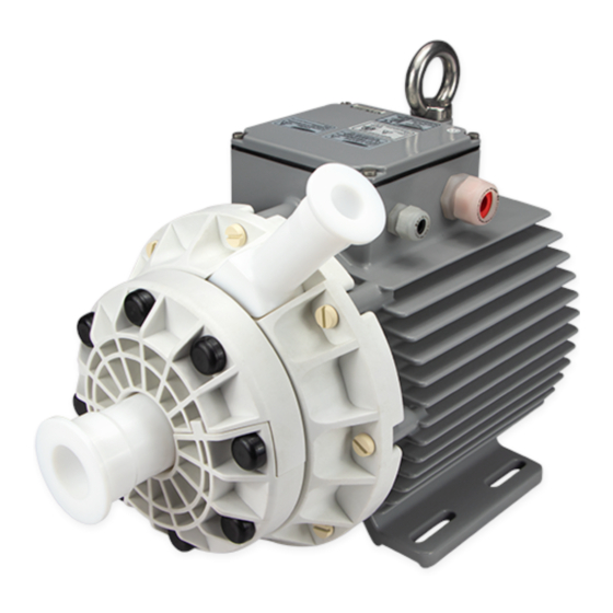
2 Specifications 2.1 Specification of Components Figure 1 shows the main system components (motor, controllers, and pump head) and Figure 2 illustrates the accessories. Figure 1: Pump system BPS-4000 with standard components Figure 2: Pump system accessories PL-4016-00, Rev11, DCO# 18-057... - Page 5 User Manual for BPS-4000 www.levitronix.com System Name Article # Pump Head Motor Controller Note Adaptor/Extension (0.5 – 10 m) cables to be ordered according to Table 3 (4a and 4b). BPS-4000.27 100-90962 LPC-4000.1 LPM-4000.2 BPS-4000.28 100-90963 LPC-4000.2 Certifications: CE, IECEE CB scheme, ETL (NRTL).
-
Page 6: Standard System Configurations
2.2 Standard System Configurations 2.2.1 Stand-Alone System Configuration The stand-alone configuration of the BPS-4000 pump system (see Figure 3) consists of a controller with an integrated user panel to set the speed manually. The speed is automatically stored in the internal EEPROM of the controller. -
Page 7: Atex / Iecex System Configuration
User Manual for BPS-4000 www.levitronix.com 2.2.3 ATEX / IECEx System Configuration Together with the standard pump-head and controllers an ATEX / IECEx certified motor allows installation of motor and pump-head within an Ex Zone 2 area (see Figure 5). The ATEX / IECEx motor (Pos. 2b in Table 2) comes delivered with special connectors and according extension cables (Pos. -
Page 8: Pressure-Flow Curves
User Manual for BPS-4000 www.levitronix.com 2.3 Pressure-Flow Curves [gallons/min] 8000 rpm Specific gravity = 1 g/cm Viscosity = 0.7 cP Liquid Temp.: 40 C 7000 rpm Limits for up to 70 C [bar] liquid temperature [psi] Limits at 90 C... -
Page 9: Maximum Static Pressure Of Pump Heads
User Manual for BPS-4000 www.levitronix.com 2.5 Maximum Static Pressure of Pump Heads [°F] LPP-4000.5/7 Pump Heads (Flange): Based on max. static pressure testing and dynamic pressure testing with safety factor. Max. pressure testing done at 20 b ar and 90 C liquid temperature without leakage and deformation. -
Page 10: Basic Dimensions Of Main Components
User Manual for BPS-4000 www.levitronix.com 2.7 Basic Dimensions of Main Components Flange Design: Separable half-flange concept PFA Coated Stainless Steel Spec. Pump Motor Screws: ANSI CLASS 150 Dimensions: 8x M10x35 ANSI/ASME B16.5-2003 Material: SS PTFE Coated Torque Spec.: 120 Ncm Spec. - Page 11 User Manual for BPS-4000 www.levitronix.com Cable Cable OD Cable OD Minimum Bending Radius Minimum Bending Radius Jacket Motor Sensor Motor Power Permanent Installation Sometimes Moved 6.6 mm 10.4 mm 7x Cable OD 15 x Cable OD 7.2 mm 12.3 mm...
- Page 12 User Manual for BPS-4000 www.levitronix.com LPC-4000.1 LPC-4000.2 Figure 13: Basic dimensions (in mm and [inch]) of LPC-4000.1/2 controllers PL-4016-00, Rev11, DCO# 18-057...
-
Page 13: Engineering Information
User Manual for BPS-4000 www.levitronix.com 3 Engineering Information 3.1 Sealing and Material Concept Figure 14: Sealing and material concept of LPP-4000.5/7 pump head Item System Materials Component Description Pump housing (lid and bottom) PTFE ANSI flange rings 1.5” Inlet / 1” outlet... -
Page 14: Ac Supply And Power Consumption
User Manual for BPS-4000 www.levitronix.com 3.2 AC Supply and Power Consumption 3.2.1 Power Consumption [gallons/min] 4500 8000 rpm Specific gravity = 1 g/cm Viscosity = ~ 0.7 cP 4000 7000 rpm Liquid Temp.: 40 3500 6000 rpm 3000 2500 5000 rpm... -
Page 15: Earth Leakage Current
User Manual for BPS-4000 www.levitronix.com Situation t Value in [A Peak Value in [A] Switch-on after complete discharge of controller (> 60 s). For this case inrush current limiter in the controller are active. Switch-on after in-complete discharge (< 60 s, worst case) -
Page 16: Thermal Management
User Manual for BPS-4000 www.levitronix.com 3.4 Thermal Management 3.4.1 Motor Temperature The motor temperature depends on the ambient and liquid temperature, as well as on the hydraulic operation point and the characteristics (viscosity and density) of the liquid. Figure 18 illustrates the temperature characteristics of the motor depending on these parameters. - Page 17 User Manual for BPS-4000 www.levitronix.com [gallons/min] Absolute Temperature Limit Recommended Operational Limit 8000 rpm 6000 rpm 7000 rpm 5000 rpm [°C] Ambient Temp = 25 C Liquid Temp. = 40 C Specific gravity = 1 g/cm Viscosity = 0.7 cP Air cooling with ACM-4000.1...
-
Page 18: Controller Temperature
User Manual for BPS-4000 www.levitronix.com 3.4.2 Controller Temperature Depending on the ambient temperature and the placement of the controller additional cooling may be required (see Figure 21). To improve cooling of the controller, place the device into a moving air stream. If the controller is mounted in a compact area or adjacent to additional heat sources (e.g. -
Page 19: Hydraulic Circuit Design
User Manual for BPS-4000 www.levitronix.com 3.5 Hydraulic Circuit Design Following general design rules for the hydraulic circuit shall be considered for a robust operation of the pump system and optimum priming behavior: 1. The general rule for optimum priming behavior is to minimize the pressure drop in the inlet circuit and avoid negative pressure at the inlet of the pump head. -
Page 20: Installation
User Manual for BPS-4000 www.levitronix.com 4 Installation 4.1 Electrical Installation of Controller 4.1.1 Overview The LPC-4000 controllers have signal processor controlled power converters with switched inverters for the drive and the bearing windings of the motor. The signal processor allows precise control of pump speed and impeller position. - Page 21 User Manual for BPS-4000 www.levitronix.com Figure 24: Overview of the controller LPC-4000.2 for extended operation Interface (as labeled) Description Position, field and temperature sensor signals from motor. “SENSORIC” Torque specification for tightening of connector screws: Min. = 0.4 Nm, Max. = 0.6 Nm - Analog current input: 4 –...
-
Page 22: General Installation Instructions
User Manual for BPS-4000 www.levitronix.com 4.1.2 General Installation Instructions WARNING Hazardous voltage may be present. Always isolate the electrical power supply before making or changing connections to the unit. To remove the power it is recommended to use an isolating device. -
Page 23: Electrical Installation Of Controller Lpc-4000.1 For Standalone Operation
User Manual for BPS-4000 www.levitronix.com 4.1.3 Electrical Installation of Controller LPC-4000.1 for Standalone Operation For standalone operation the LPC-4000.1 is disabled when power is turned on. It can be enabled manually by using the “UP” button on the display. If the controller shall be enabled automatically, when power is applied the “ENABLE”... -
Page 24: Installation Extended Controller Lpc-4000.2 With Plc Interface
User Manual for BPS-4000 www.levitronix.com 4.1.5 Installation Extended Controller LPC-4000.2 with PLC Interface To operate the pump system with a PLC, a minimum set of two digital inputs and one analog input is needed. The digital and analog outputs can be used to monitor the pump status and operating parameters. - Page 25 User Manual for BPS-4000 www.levitronix.com Connector Wire name Designation Levels Note 4..20 mA = 0..10000 rpm (speed mode) Analog In1, (Signal) -> Speed Limit = 8000 rpm 16.8 A Ref Value -> Cut-off (min.) speed = 300 rpm (Current Input) - Grounds are internally connected.
-
Page 26: Mechanical Installation Of The Pump/Motor
User Manual for BPS-4000 www.levitronix.com 4.2 Mechanical Installation of the Pump/Motor 4.2.1 Standard Installation Instructions and Information WARNING Overheating of the Motor Power and Extension Power Cable To prevent an overheating of the motor power and extension power cables, do not roll-up or install several motor power cables in the same cable channel. - Page 27 User Manual for BPS-4000 www.levitronix.com An Ex conform solution is needed for the motor cable to leave the Ex area (see Figure 5). One option is an Ex certified cable sealing system as listed in Table 4 (see Pos. 8) and shown in Figure 2.
-
Page 28: Mechanical Installation Of The Controller
If explosive flammable gases are present, place the controller in an explosion-proof cabinet. CAUTION Do not under any circumstances open the controller. Levitronix does not assume responsibility for any damage, which occurs under such circumstances. 4.4 Mechanical Installation of Adaptor/Extension Cables For connecting the motor to the controller the adaptor cables MCAP-4000.x (for power cable) and MCAS-... -
Page 29: Operation
User Manual for BPS-4000 www.levitronix.com 5 Operation 5.1 System Operation with LPC-4000.1 (Stand-Alone Version) 5.1.1 State Diagram of LPC-4000.1 The controller LPC-4000.1 allows stand-alone operation with manual speed setting (“Button Control Mode”) as well as extended operation with analog speed setting (Analog Control Mode). Figure 33 shows the state diagram which can be controlled with the manual buttons and the signals on the “USER INTERFACE”... -
Page 30: Standalone Operation (Button Control Mode)
User Manual for BPS-4000 www.levitronix.com 5.1.2 Standalone Operation (Button Control Mode) ▪ When applying power, the system defaults into the “Button Control Mode” and goes into the status “OFF ButtonControl” according to Figure 33. Levitation is disabled and the display indicates “OF”. -
Page 31: Extended Operation ("Analog Control Mode")
User Manual for BPS-4000 www.levitronix.com 5.1.3 Extended Operation (“Analog Control Mode”) ▪ In order to be able to control the pump with external signals (PLC) the mode “Analog Control Mode” has to be set with the display buttons. The “UP” and “Down” buttons have to be pressed simultaneously during 5 seconds. -
Page 32: System Operation With Controller Lpc-4000.2 (Plc Version)
User Manual for BPS-4000 www.levitronix.com 5.2 System Operation with Controller LPC-4000.2 (PLC Version) 5.2.1 State Diagram of the PLC Interface Power On Enable: not active Reset: active Status : not active State 1 Priming: on Enable: active Reset: not active... - Page 33 User Manual for BPS-4000 www.levitronix.com State “Off”: ® The pump system is switched off and the motor has no power. In this state, Levitronix Service Software has full control. State “ON” (Speed Control Mode): The pump system is switched ON and the impeller is rotating with the referenced speed. The motor has electrical power when in this state.
-
Page 34: System Operation For Atex / Iecex And Cl1 Div2 Applications
User Manual for BPS-4000 www.levitronix.com 5.3 System Operation for ATEX / IECEx and Cl1 Div2 Applications 5.3.1 General Safety Requirements Specific precautions may be considered while using the pump system in potential explosive gas atmospheres according to ATEX/IECEx category 3G/3D (Zone 2 and 22) Hazardous Location Cl1/Cl2 Div2. -
Page 35: Inspection And Maintenance
The impeller has a limited lifetime depending on the chemical type, concentration and temperature of the fluid which is pumped. Therefore, a preventive periodical exchange of the impeller is recommended. Contact the Levitronix Technical Service Department (see Section 8) for further information on replacement times. 6.2 Impeller Replacement Procedure 6.2.1 Preparation... -
Page 36: Instructions For Replacement
User Manual for BPS-4000 www.levitronix.com 6.2.2 Instructions for Replacement 1. Power down the pump system and remove the AC supply voltage. It is necessary to let cool down to a workable temperature (near ambient) before the impeller can be ex- changed. - Page 37 User Manual for BPS-4000 www.levitronix.com 7. Remove the Pump Housing Lid with the O- 9. Assemble the new O-Ring to the Pump Casing Ring. Remove the Impeller. Inspect the wet Lid and make sure that it is properly aligned to area of the pump head carefully.
- Page 38 User Manual for BPS-4000 www.levitronix.com 11. Press the pump casing into the Reinforcement Ring, mount the Axial Support Plate and add the two Semi Fixation Rings. 12. Tighten the 8 Pump Mounting Screws (with relevant washers) crosswise symmetric regular on the semi fixation rings and add the Protective Screw Covers.
-
Page 39: Troubleshooting
USB interface. The software can be used for performing detailed troubleshooting. For usage of the Service Software refer to the Service Software User Manual (Document #: PL-2034-00), which is available in the download section on the Levitronix Web-page or contact the Levitronix Technical Service Department (see under Section 8). -
Page 40: Appendix
The CB certification number is CH-7449. 9.1.3 NRTL/ETL Safety Certification and Marking Specific motors with pump heads and controllers of the Centrifugal Pump System BPS-4000 are tested by the US national recognized laboratory (NRTL) Intertek according to the following safety standards: UL61010-1 Safety requirements for electrical equipment for measurement, control and laboratory (US Standard). -
Page 41: Atex / Iecex Certification And Marking
9.1.4 ATEX / IECEx Certification and Marking Specific motors together with the pump head of the BPS-4000 pump system are in conformity with the requirements of the Directive 2014/34/EU and the applicable IEC standards. The following standards are tested and confirmed at a certified laboratory. -
Page 42: Immunity To Voltage Sags - Semi F47
BPS-4000 in its various configurations is able to handle all the voltage sags defined in SEMI F47. Therefore the pump system BPS-4000 full fills the requirements of the SEMI F47 standard. The nominal voltage range is 200 – 240 VAC ±10% for operation without performance reduction. -
Page 43: Symbols And Signal Words
User Manual for BPS-4000 www.levitronix.com 9.2 Symbols and Signal Words Symbol / Description Type Source Signal Word Indication of an imminently hazardous situation that, if DANGER not avoided, will result in death or severe injury. Signal word SEMI S1-0701 Limited to the most extreme situation...
Need help?
Do you have a question about the BPS-4000 and is the answer not in the manual?
Questions and answers