Table of Contents
Advertisement
Quick Links
User Manual for BPS-i30
www.levitronix.com
BPS-i30
USER MANUAL
This manual contains information necessary for the safe and proper use of the BPS-i30. Included are
specifications for the standard configurations of the flow control system and instructions regarding its use,
installation, operation, adjustment, inspection and maintenance. For special configurations of the pump
system refer to accompanying information. If the pump system must be configured for other parameter
®
settings, then the Levitronix
Service Software version V2.0.5.0 or higher (with relevant manual Levitronix
Doc.# PL-4043-00) is necessary. Familiarize yourself with the contents of the manual to ensure the safe
and effective use of this product. After reading this manual, please store the manual where the personnel
responsible for operating the flow control system can readily refer to it at any time.
First Release: 11-Jun-2014
PL-4042-00, Rev05, DCO# 21-057
Last Update: 12-Mar-2021
Advertisement
Table of Contents

Related Manuals for Levitronix BPS-i30


Summary of Contents for Levitronix BPS-i30
- Page 1 BPS-i30 USER MANUAL This manual contains information necessary for the safe and proper use of the BPS-i30. Included are specifications for the standard configurations of the flow control system and instructions regarding its use, installation, operation, adjustment, inspection and maintenance. For special configurations of the pump system refer to accompanying information.
-
Page 2: Table Of Contents
User Manual for BPS-i30 www.levitronix.com Table of Contents SAFETY PRECAUTIONS..................................3 SPECIFICATIONS ....................................4 Specification of Components .................................4 System Overview and General Specification ..........................6 2.2.1 System Configuration for Stand-Alone Model ..............................6 2.2.2 System Configuration for EasyConnect Model ..............................6 2.2.3 System Configuration for OEM Models ................................7 2.2.4... -
Page 3: Safety Precautions
1 Safety Precautions The BPS-i30 pump system is designed to be used in industrial production machines and equipment containing hydraulic circuits. Typical applications are Semiconductor and chemical manufacturing equipment. Installation shall be done by qualified personnel only. Following safety precautions and all “CAUTION”, “WARNING” and “DANGER”... -
Page 4: Specifications
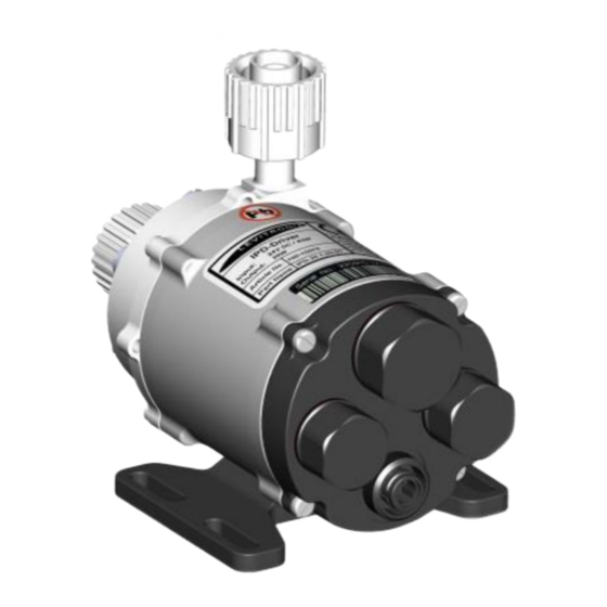
User Manual for BPS-i30 www.levitronix.com 2 Specifications 2.1 Specification of Components Figure 1: Pump system with main standard components Figure 2: General Accessories Figure 3: Cables and cable accessories PL-4042-00, Rev05, DCO# 21-057... - Page 5 Article # Pump Head Driver Note BPS-i30.1 / 13 / 7 100-90831 / 91209 / 91187 LPP-30.1 / 3 / 6 IPD-30.1-50-01 / 03 / 04 OEM - Epoxy coated driver, 5 m PVC cable with open wires, PTFE pump head.
-
Page 6: System Overview And General Specification
User Manual for BPS-i30 www.levitronix.com 2.2 System Overview and General Specification 2.2.1 System Configuration for Stand-Alone Model Figure 4 illustrates the system configuration of the Stand-Alone model with integrated user panel and buttons to set the speed manually. The driver also contains a PLC interface for remote speed control by analog and digital signals. -
Page 7: System Configuration For Oem Models
Various digital inputs and outputs allow controlling and monitoring of the system. A RS485 enables ® communication with a PC with the Levitronix Service Software. Hence parameterization, firmware updates and failure analysis are possible. The RS485 can also be used as a fieldbus to implement more intelligent concepts of pump control. -
Page 8: System Configuration For Oem Atex / Iecex Models
User Manual for BPS-i30 www.levitronix.com The PLC interface of the OEM model enables the implementation of precise closed loop flow or pressure control in connection with either a flow or pressure sensor (see Figure 8). Precise ultrapure flow control ®... -
Page 9: General Environmental Conditions
User Manual for BPS-i30 www.levitronix.com Outlet Flow Cabinet Boundary for or Pressure Ex classified Area Sensor AC/DC Power Supply Sensor Feedback for Flow or Pressure Control (24VDC, DIN-Rail) DC Output AC Input Cable Bushing Inlet Integrated Ex Pump Driver Integrated Driver Cable... -
Page 10: Pressure-Flow Curves
User Manual for BPS-i30 www.levitronix.com 2.4 Pressure-Flow Curves [gallons / min] 15000 rpm «Standard» Specific gravity = 1 g/cm Thermal Limit 65°C Driver Viscosity = 0.7 cP 70°C Liquid, 25°C Ambient Liquid Temp.: 40 °C DC-Voltage = 24 V 14000 rpm Pump Head: LPP-30.1... -
Page 11: Maximum Static Pressure For Pump Heads
User Manual for BPS-i30 www.levitronix.com 2.5 Maximum Static Pressure for Pump Heads [°F] Ambient Temp = 25 °C Note: Pressure limit only valid for pump head mounted on motor. Max. Static Pressure for LPP-30.1/3: Based on max. static pressure testing according to EN12162 with safety factor and dynamic pressure testing. - Page 12 User Manual for BPS-i30 www.levitronix.com Pump Head Inlet and Outlet Fitting: LPP-30.1/3: Pillar Super 3/8“ FM LPP-30.6: Pillar Super 1/2” FM +10.5 mm for LPP-30.6 +12 mm for LPP-30.6 Figure 14: Basic dimensions and description of standard “EasyConnect” models (Non-tolerated dimensions are for reference only.)
- Page 13 User Manual for BPS-i30 www.levitronix.com Driver IPD-30.x Slot for Driver Mounting with M4 screws Mounting Base Plate MBP-i30.1 Material: PP+GF30 Countersunk Head Screws M3 x 10mm, FEP coated Figure 16: Basic dimensions (in [mm] and [inch]) of mounting base plate MBP-i30.1 (Context with driver IPD-30.x.
- Page 14 User Manual for BPS-i30 www.levitronix.com 4pcs M3x10 Screws (SS PTFE coated, torque spec: 15 Ncm) (For pump head motor mounting. Motor has 8 mounting holes and therefore can be rotated by 45 degree) Pump Head Inlet and Outlet Fitting: Pillar Super 3/8“ FM (ID = 6.4 mm) 6pcs M5x14 Screws (SS PTFE coated, torque spec.
-
Page 15: Engineering Information
User Manual for BPS-i30 www.levitronix.com 3 Engineering Information 3.1 Sealing and Material Concept Figure 20: Sealing and material concept (Driver IPD-30.1-50 with pump heads LPP-30.1/3/6) Item System Materials Component Description Pump housing lid and bottom PTFE Static sealing O-ring of pump casing... -
Page 16: Power Supply And Consumption
User Manual for BPS-i30 www.levitronix.com 3.2 Power Supply and Consumption 3.2.1 Power Consumption [gallons / min] 15000 rpm Specific gravity = 1g/cm 14000 rpm Viscosity = 0.7cP Liquid Temp.: 40°C 13000 rpm Pump Head: LPP-30.1 12000 rpm 11000 rpm 10000 rpm... -
Page 17: Inrush Current
(see ® explanation in Section 3.4). The warning signal can be monitored with the Levitronix Service Software or configured on one of the digital outputs. - Page 18 User Manual for BPS-i30 www.levitronix.com [gallons / min] Absolute Thermal Limit Ambient Temp = 25°C Liquid Temp. = 25°C Specific gravity = 1 g/cm Viscosity = 0.7 cP Temp. Time Constant = ~40 min Pump Head: LPP-30.1 Recommended Operational Thermal Limit [°C]...
- Page 19 User Manual for BPS-i30 www.levitronix.com [gallons / min] Absolute Thermal Limit 10000 rpm 11000 rpm 15000 rpm 14000 rpm 13000 rpm 12000 rpm Recommended Operational Limit 9000 rpm 8000 rpm [°C] 7000 rpm [°F] Ambient Temp = 25 °C Liquid Temp. = 70 °C Specific gravity = 1 g/cm Viscosity = 0.7 cP...
- Page 20 User Manual for BPS-i30 www.levitronix.com [gallons / min] Absolute Thermal Limit Recommended Operational Limit 15000 rpm [°C] 13000 rpm 10000 rpm 7000 rpm [°F] 5000 rpm Ambient Temp = 25°C Liquid Temp. = 90°C Specific gravity = 1g/cm3 Viscosity = 0.7cP Temp.
-
Page 21: Hydraulic Circuit Design
User Manual for BPS-i30 www.levitronix.com 3.5 Hydraulic Circuit Design Following general design rules for the hydraulic circuit shall be considered for a robust operation of the pump system and optimum priming behavior: 1. The general rule for optimum priming behavior is to minimize the pressure drop in the inlet circuit and avoid negative pressure at the inlet of the pump head. -
Page 22: Installation
User Manual for BPS-i30 www.levitronix.com 4 Installation 4.1 Electrical Installation of Stand-Alone Model Power Supply Connector PLC Connector Figure 26: Electrical connections to Stand-Alone driver IPD-30.5 Wire Standard Specifications Pin # Description Note Name Color Designation Typical Levels + 24 VDC Voltage: 24 VDC ±10%... -
Page 23: Overview Electrical Schematics Of Stand-Alone Driver Interface
User Manual for BPS-i30 www.levitronix.com 4.1.1 Overview Electrical Schematics of Stand-Alone Driver Interface Example of User Levitronix Driver Interface Circuit Interface Circuit Pin 2: Digital Input 2.2 k 5..24 V Pin 4: Common Digital Input Pin 6: Analog Input 450 ... -
Page 24: Installation Instructions Of Power Supply
Consult Figure 21 to get the power consumption depending on the ® flow. If other power supplies are used, than the one recommended by Levitronix , it is highly recommended to test these under dynamic conditions (acceleration and braking of the pump rotor speed). -
Page 25: Electrical Installation Of Easyconnect Model
User Manual for BPS-i30 www.levitronix.com 4.2 Electrical Installation of EasyConnect Model 4.2.1 Overview of Connections and Designations PLC Connector Fieldbus OUT Fieldbus IN Power Supply Connector Figure 28: Electrical connections to EasyConnect driver IPD-30.3 Wire Standard Specifications Pin # Description... - Page 26 Switch between process mode and speed Din2 grey Process Mode not active mode. In process mode the closed loop PI ® controller can be configured with Levitronix Service Software. Common Din_COM yellow Reference to Din1 and Din2. Digital Input 24 VDC ±10%, 200 mA...
-
Page 27: Overview Electrical Schematics Of Driver Interface
User Manual for BPS-i30 www.levitronix.com 4.2.2 Overview Electrical Schematics of Driver Interface Levitronix Driver Interface Circuit Example of User Interface Circuit Pin 5: Digital Input 1 2.2 k Pin 4: Digital Input 2 5..24 V 2.2 k Pin 3: Common Digital Input Pin 7: Analog Input 1 450 ... -
Page 28: Installation Instructions For Power Supply
Consult Figure 21 to get the power consumption depending on the ® flow. If other power supplies are used than the one recommended by Levitronix , it is highly recommended to test these under dynamic conditions (acceleration and braking of the pump rotor speed). -
Page 29: Installation Of Rs485 Fieldbus Multi-Pump System Arrays
Technical Service department (see Section 8) for details and support. ® ➔ Address setting of the pump units can be done with the Levitronix Service Software and a PC. A USB/RS485 converter cable with integrated initialization network can be ordered according to Table 3 ➔... -
Page 30: Electrical Installation Of Oem Model
Table 14: Signals of the driver cable with designation for standard firmware Note 1: For other configurations of PLC Inputs and Outputs refer to alternate firmware documentation ® Note 2: Configurations can be done with Levitronix Service Software. Note 3: Power wires (P+, P-) have cross section 1.5 mm and all others 0.14 mm... -
Page 31: Overview Electrical Schematics Of Driver Interface
User Manual for BPS-i30 www.levitronix.com 4.3.2 Overview Electrical Schematics of Driver Interface Cable Wires (UL Cable) Example of User Levitronix Driver Colours/Designation Interface Circuit Interface Circuit Pink: Digital Input 1 2.2 k 5..24 V Grey: Digital Input 2 2.2 k... -
Page 32: Installation Instructions For Power Supply
Figure 21 to get the power consumption depending on the flow. If other power supplies are used, than the one recommended by Levitronix, it is highly recommended to test these under dynamic conditions (acceleration and braking of the pump rotor speed). -
Page 33: Installation Of Rs485 Fieldbus Multi-Pump System Arrays
Technical Service department (see Section 8) for details and support. ➔ ® Address setting of the pump units can be done with the Levitronix Service Software and a PC. A Table 3 USB/RS485 converter cable with integrated initialization network can be ordered according to ®... -
Page 34: Mechanical Installation Of Stand-Alone And Easyconnect Model
User Manual for BPS-i30 www.levitronix.com 4.5 Mechanical Installation of Stand-Alone and EasyConnect Model The Stand-Alone and EasyConnect model are delivered with the mounting base plate MBP-i30.1, which can be used to fix the driver with four screws on the mounting slots of the base plate (see Figure 13 for the Stand- Alone and Figure 14 for the EasyConnect model). -
Page 35: Operation
User Manual for BPS-i30 www.levitronix.com 5 Operation 5.1 Operation of Stand-Alone Model 5.1.1 Manual Operation With the Stand-Alone model the system can be operated manually with the user panel according to Figure 35. The speed can be set manually with the... -
Page 36: Detailed State Diagram
User Manual for BPS-i30 www.levitronix.com 5.1.4 Detailed State Diagram Figure 35 shows the detailed state diagram, which can be controlled with the manual buttons or the signals of the PLC interface connector. Power Auto-Start (Menu Tab1) Set setpoint speed pressing... - Page 37 User Manual for BPS-i30 www.levitronix.com State “Off”: The pump system is switched off and the motor phases have no power (current). The Setpoint Speed can be modified with the Down buttons, without any effect on the system states. State “On (Speed Control)”:...
-
Page 38: Operation Of Easyconnect And Oem Model
User Manual for BPS-i30 www.levitronix.com 5.2 Operation of EasyConnect and OEM Model 5.2.1 Operation with PLC Power On Enable: Status : not active not active State 1 Reset: Pulse 300-700 ms Priming: on Enable: active Priming: off Enable: not active... -
Page 39: Operation With Fieldbus (Rs485)
User Manual for BPS-i30 www.levitronix.com State “Off”: ® The pump system is switched off and the motor has no power. In this state, Levitronix Service Software has full control. State “ON” (speed control mode): The pump system is switched ON and the impeller is rotating with the referenced speed. The motor has electrical power when in this state. -
Page 40: Operation For Atex / Iecex Application
User Manual for BPS-i30 www.levitronix.com 5.3 Operation for ATEX / IECEx Application Specific precautions may be considered while using the pump system in potential explosive gas atmospheres according to ATEX / IECEx category 3G/3D (Zone 2 and 22). The user shall prevent priming issues during normal pump operation. Especially precautions have to be considered during installing and maintenance operations to prevent the occurrence of combustible atmospheres. -
Page 41: Inspection And Maintenance
User Manual for BPS-i30 www.levitronix.com 6 Inspection and Maintenance 6.1 Replacement Interval of the Impeller The impeller has a limited lifetime depending on the chemical type, concentration and temperature of the fluid which is pumped. Therefore, a preventive periodical exchange of the impeller is recommended. Contact the ®... -
Page 42: Instructions For Replacement
User Manual for BPS-i30 www.levitronix.com 6.2.2 Instructions for Replacement 1. Power down the pump system and remove the 6. If necessary, remove the existing O-Ring and AC power. If necessary, allow the housing to gently press the new O-Ring into the lid of the cool down to a workable temperature. -
Page 43: Troubleshooting
7.2.3 Troubleshooting with User Panel LUI-B.1 For troubleshooting and failure analysis with the user panel LUI-B.1 the integrated display gives advice about status and potential failure details. 8 Technical Support For troubleshooting, support and detailed technical information contact Levitronix Technical Service Department: Levitronix Technical Service Department Technoparkstr. -
Page 44: Appendix
Generic standards, Emission standard for industrial environments 9.1.2 ATEX / IECEx Certification and Marking Specific pump drivers with pump heads of the BPS-i30 pump system together with specific accessories are in conformity with the requirements of the Directive 2014/34EU and the applicable IEC standards. The following standards are tested and confirmed at a certified laboratory. -
Page 45: Symbols And Signal Words
User Manual for BPS-i30 www.levitronix.com 9.2 Symbols and Signal Words Symbol / Description Type Source Signal Word Indication of an imminently hazardous situation that, if not DANGER Signal word SEMI S1-0701 avoided, will result in death or severe injury. Limited to the...
Need help?
Do you have a question about the BPS-i30 and is the answer not in the manual?
Questions and answers