Keysight E8267D User Manual
Psg signal generators
Hide thumbs
Also See for E8267D:
- Manual (16 pages) ,
- Installation manual (45 pages) ,
- Installation notes (11 pages)
Table of Contents
Advertisement
Quick Links
Advertisement
Table of Contents

Related Manuals for Keysight E8267D


Summary of Contents for Keysight E8267D
- Page 1 Keysight E8257D/67D & E8663D PSG Signal Generators Notice: This document contains references to Agilent. Please note that Agilent’s Test and Measurement business has become Keysight Technologies. For more information, go to www.keysight.com. User’s Guide...
-
Page 2: Safety Notices
PERFORMANCE OF THIS to the public to use, modify, DOCUMENT OR ANY INFORMATION reproduce, release, perform, CONTAINED HEREIN. SHOULD display, or disclose commercial KEYSIGHT AND THE USER HAVE A computer software or SEPARATE WRITTEN AGREEMENT commercial computer software WITH WARRANTY TERMS... - Page 3 URLs, according to the name of your product: http://www.keysight.com/find/psg To receive the latest updates by email, subscribe to Keysight Email Updates at the following URL: http://www.keysight.com/find/MyKeysight Information on preventing instrument damage can be found at: www.keysight.com/find/PreventingInstrumentRepair...
-
Page 5: Table Of Contents
E8267D PSG Vector Signal Generator Features ........ - Page 6 32. EXT 1 ................40 Keysight E8357D/67D & E8663D PSG User’s Guide...
- Page 7 43. LF OUT................42 44. Flash Drive (Serial Prefixes >=US4829/SG4829/MY4829 (E8267D) and >=US4928/SG4928/MY4928 (E8257D)).
- Page 8 Editing a Waveform Sequence ............. 107 Adding Real–Time Noise to a Dual ARB Waveform (E8267D with Option 403) ..... . . 109 Storing and Loading Waveform Segments .
- Page 9 Selecting a Custom ARB Setup or a Custom Digital Modulation State ......187 Keysight E8357D/67D & E8663D PSG User’s Guide...
- Page 10 RF Power Level Considerations ............239 Keysight E8357D/67D & E8663D PSG User’s Guide...
- Page 11 No RF Output Power when Playing a Waveform File (E8267D only) ......
- Page 12 Returning a Signal Generator to Keysight Technologies........
-
Page 13: Signal Generator Overview
— Getting Started with Remote Operation Programming Guide — Using IO Interfaces — Programming Examples — Programming the Status Register System — Creating and Downloading Waveform Files — Creating and Downloading User-Data Files Keysight E8357D/67D & E8663D PSG User’s Guide... - Page 14 — Digital Signal Interface Module Commands — SCPI Command Compatibility — Troubleshooting Service Guide — Replaceable Parts — Assembly Replacement — Post-Repair Procedures — Safety and Regulatory Information — Key function description Key Reference Keysight E8357D/67D & E8663D PSG User’s Guide...
- Page 15 “Front Panel Display” on page 21 — “Rear Panel” on page 26 For more information about the PSG, such as data sheets, configuration NOTE guides, application notes, frequently asked questions, technical support, software and more, visit the Keysight PSG web page at http://www.keysight.com/find/psg.
-
Page 16: Signal Generator Models And Features
E8663D PSG analog signal generator 100 kHz to 3.2 GHz (Option 503) 100 kHz to 9 GHz (Option 509) a. Instruments with Option 567 are functional, but unspecified, above 67 GHz to 70 GHz Keysight E8357D/67D & E8663D PSG User’s Guide... -
Page 17: E8257D Psg Analog Signal Generator Features
E8257D PSG Analog Signal Generator Features The E8257D PSG includes the following standard features: — a source module interface that is compatible with Keysight 83550 Series millimeter–wave source modules for frequency extension up to 110 GHz and Oleson Microwave Labs (OML) AG–Series millimeter–wave modules for frequency extensions up to 325 GHz —... - Page 18 Signal Generator Overview Signal Generator Models and Features Option 1EU—high output power (standard with E8267D) Option 1EM—moves all front panel connectors to the rear panel Option 1SM—provides improved performance in Exponential (Log) AM mode Option UK6—commercial calibration certificate and test data Option UNR (Discontinued)—enhanced phase noise...
-
Page 19: E8267D Psg Vector Signal Generator Features
— single–ended and differential analog I/Q outputs — high output power (optional for the E8257D & E8663D) — step attenuator (optional for the E8257D) The E8267D PSG offers the same options as the E8257D PSG, plus the following: Option 003—PSG digital output connectivity with N5102A Option 004—PSG digital input connectivity with N5102A... - Page 20 Signal Generator Overview Signal Generator Models and Features — a source module interface that is compatible with Keysight 83550 Series millimeter–wave source modules for frequency extension up to 110 GHz and Oleson Microwave Labs (OML) AG–Series millimeter–wave modules for frequency extensions up to 325 GHz —...
-
Page 21: Keysight E8357D/67D & E8663D Psg User's Guide
Option 1EA (Discontinued)—high output power Option 1ED—Type–N female RF output connector Option 1EH —improved harmonics below 2 GHz Option 1EU—high output power (standard with E8267D) Option 1EM—moves all front panel connectors to the rear panel Option 1EZ—extended support life Option 1SM—provides improved performance in Exponential (Log) AM mode Option UK6—commercial calibration certificate and test data... -
Page 22: Options
PSG signal generators have hardware, firmware, software, and documentation options. The Data Sheet shipped with your signal generator provides an overview of available options. For more information, visit the Keysight PSG web page at http://www.keysight.com/find/psg, select the desired PSG model, and then click the Options tab. -
Page 23: Keysight E8357D/67D & E8663D Psg User's Guide
When the User Attention message appears, you must first cycle the instrument’s power, then click OK. When the upgrade completes, the Upgrade Assistant displays a summary. 15.Click OK and close the Upgrade Assistant. Keysight E8357D/67D & E8663D PSG User’s Guide... -
Page 24: Modes Of Operation
E8267D, and E8663D can produce a CW signal. Swept Signal In this mode, the signal generator sweeps over a range of frequencies and/or power levels. The E8257D, E8267D, and E8663D provide list and step sweep functionality. Option 007 adds analog ramp sweep functionality. Analog Modulation In this mode, the signal generator modulates a CW signal with an analog signal. -
Page 25: Keysight E8357D/67D & E8663D Psg User's Guide
Custom Arb Waveform Generator mode, or downloaded through a remote interface into the ARB memory. To learn more, refer to “Using the Dual ARB Waveform Player” on page 103. Keysight E8357D/67D & E8663D PSG User’s Guide... -
Page 26: Front Panel
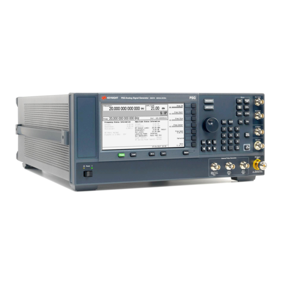
Front Panel Front Panel This section describes each item on the PSG front panel. Figure 1-1 shows an E8267D front panel, which includes all items available on the E8257D and E8663D. Figure 1-1 Standard E8267D Front Panel Diagram 10 11 12... -
Page 27: Display
6. Save The Save hardkey does not save table configurations, such as list sweep, CAUTION multitone, or ARB. Keysight E8357D/67D & E8663D PSG User’s Guide... -
Page 28: Recall
Recall and enter the desired sequence number and register number. To save a state, use the Save hardkey. For more information on saving and recalling instrument states, refer to “Using the Instrument State Registers” on page Keysight E8357D/67D & E8663D PSG User’s Guide... -
Page 29: Trigger
— More (1 of 2) > Point Trigger > Trigger Key 9. MENUS These keys open softkey menus for configuring various functions. For descriptions, see the Keysight PSG Signal Generators Key Reference. Table 1-3 Hardkeys in Front Panel MENUS Group... -
Page 30: Ext 1 Input
14. Mod On/Off This hardkey (E8267D and E8257D with Options UNT, UNU, or UNW) enables or disables all active modulation formats (AM, FM, ΦM, Pulse, or I/Q) applied to the output carrier signal available through the RF OUTPUT connector. This hardkey does not set up or activate an AM, FM, ΦM, Pulse, or I/Q format;... -
Page 31: Rf On/Off
This hardkey enables you to set the increment value of the current active function. The increment value of the current active function appears in the active entry area of the display. Use the numeric keypad, arrow hardkeys, or the knob to adjust the increment value. Keysight E8357D/67D & E8663D PSG User’s Guide... -
Page 32: Gate/ Pulse/ Trigger Input
Pressing this hardkey causes the display background to lighten. 28. Local Pressing this hardkey deactivates remote operation and returns the signal generator to front–panel control. 29. Preset Pressing this hardkey sets the signal generator to a known state (factory or user–defined). Keysight E8357D/67D & E8663D PSG User’s Guide... -
Page 33: Line Power Led
DATA and SYMBOL SYNC signals. The maximum clock rate is 50 MHz. The damage levels are > +5.5 V and < −0.5V. The nominal input impedance is not definable. On signal generators with Option 1EM, this connector is located on the rear panel. Keysight E8357D/67D & E8663D PSG User’s Guide... -
Page 34: Data
Option 1EM, these connectors are located on the rear panel. 37. I Input This female BNC input connector (E8267D only) accepts the in–phase (I) component of an externally supplied, analog, I/Q modulation. The quadrature–phase (Q) component is supplied through the Q INPUT. The signal level is = 0.5 V... -
Page 35: Front Panel Display
Front Panel Display Diagram Table 1-4 1. Active Entry Area 5. Amplitude Area 2. Frequency Area 6. Error Message Area 3. Annunciators 7. Text Area 4. Digital Modulation Annunciators 8. Softkey Label Area Keysight E8357D/67D & E8663D PSG User’s Guide... -
Page 36: Active Entry Area
ARMED initiated and the signal generator is waiting for the sweep trigger event. This annunciator (E8267D, E8257D, or E8663D with ATTEN HOLD Option 1E1 only) appears when the attenuator hold function is on. When this function is on, the attenuator is held at its current setting. - Page 37 This annunciator (Option UNT only) appears when frequency modulation is turned on. If phase modulation is turned on, the ΦM annunciator will replace FM. This annunciator (E8267D only) appears when I/Q modulation is turned on. This annunciator appears when the signal generator is in listener mode and is receiving information or commands over the RS–232, GPIB, or VXI–11 LAN...
- Page 38 Local key and the line power switch. For information on remote operation, refer to the Keysight PSG Signal Generators Programming Guide. This annunciator indicates when the RF or microwave...
-
Page 39: Digital Modulation Annunciators
4. Digital Modulation Annunciators All digital modulation annunciators (E8267D with Option 601/602 only) appear in this location. These annunciators appear only when the modulation is active, and only one digital modulation can be active at any given time. -
Page 40: Rear Panel
Rear Panel This section describes each item on the PSG rear panel. Four consecutive drawings show the standard and Option 1EM rear panels for the E8267D, E8257D, and the E8663D. (Option 1EM moves all front panel connectors to the real panel.) - Page 41 37. ALC INPUT 8. I OUT 23. STOP SWEEP IN/OUT 38. DATA CLOCK 9. WIDEBAND I INPUTS 24. BASEBAND GEN CLK IN 39. I IN 10. I–bar OUT 25. Z–AXIS BLANK/MKRS 40. SYMBOL SYNC Keysight E8357D/67D & E8663D PSG User’s Guide...
- Page 42 22. 10 MHz OUT 29. SOURCE SETTLED 16. GPIB 23. STOP SWEEP IN/OUT 30. SOURCE MODULE INTERFACE 17. 10 MHz EFC 25. Z–AXIS BLANK/MKRS 44. Flash Drive (Serial Prefixes >=US4829/SG4829/MY4829 (E8267D) and >=US4928/SG4928/MY4928 (E8257D)) Keysight E8357D/67D & E8663D PSG User’s Guide...
- Page 43 36. PULSE/TRIG GATE INPUT 20. 10 MHz IN 28. TRIGGER IN 37. ALC INPUT 21. LAN 29. SOURCE SETTLED 43. LF OUT 31. RF OUT 44. Flash Drive (Serial Prefixes >=US4829/SG4829/MY4829 (E8267D) and >=US4928/SG4928/MY4928 (E8257D)) Keysight E8357D/67D & E8663D PSG User’s Guide...
-
Page 44: Event 1
Minimum pulse width is 100 ns. Damage levels are > +5.5 V and < −0.5 V. The nominal input impedance is not defined. Keysight E8357D/67D & E8663D PSG User’s Guide... -
Page 45: Burst Gate In
This female 37–pin connector is active only on instruments with an internal baseband generator (Option 601/602); on signal generators without Option 601/602, this connector is non–functional. This connector provides access to the inputs and outputs described in the following figure. Keysight E8357D/67D & E8663D PSG User’s Guide... -
Page 46: Digital Bus
6. DIGITAL BUS This is a proprietary bus used for Keysight Baseband Studio products, which require an E8267D with Options 003/004 and 601/602. This connector is not operational for general–purpose customer use. Signals are present only when a Baseband Studio option is installed (for details, refer to http://www.keysight.com/find/basebandstud io). -
Page 47: I Out
Q OUT connector is 50 ohms, dc–coupled. 8. I OUT This female BNC connector (E8267D only) is used with an internal baseband generator (Option 601/602) to output the analog, in–phase component of I/Q modulation. On signal generators without Option 601/602, this female BNC connector is used to output the in–phase component of an external I/Q... -
Page 48: Wideband Q Inputs
When not in use, this connector must be terminated with a 50 ohm load. 14. Q–bar OUT This female BNC connector (E8267D only) can be used with an internal baseband generator (Option 601/602) to output the complement of the analog, quadrature–phase component of I/Q modulation. On signal generators... -
Page 49: Ac Power Receptacle
E8257D: 100/120 VAC 50/60/400 Hz, 220/240, VAC 50/60 Hz, < 250 W typical, 450 W maximum E8267D: 100/120 VAC 50/60/400 Hz; or 220/240 VAC 50/60 Hz, (automatically selected); < 400 W typical, 650 W maximum E8663D: 100/120 VAC 50/60/400 Hz; or 220/240 VAC 50/60 Hz, (automatically selected);... -
Page 50: Alc Hold (Serial Prefixes >=Us4722/My4722)
Rear Panel 18. ALC HOLD (Serial Prefixes >=US4722/MY4722) This female BNC connector (E8267D only) is a TTL–compatible input that controls ALC action with bursted I/Q signals from an arbitrary waveform generator (AWG). A high signal allows the ALC to track the RF signal and maintain constant RF output level as the I/Q inputs vary. -
Page 51: Lan
This signal is derived from an operational amplifier output so the load impedance should be greater than or equal to 5 kohms. This connection is most commonly used to interface with an Keysight 8757D Scalar Network Analyzer. Keysight E8357D/67D & E8663D PSG User’s Guide... -
Page 52: Sweep Out
The nominal output impedance for this connector is less than 10 ohms. 30. SOURCE MODULE INTERFACE This interface is used to connect to compatible Keysight Technologies 83550 Series mm–wave source modules. Keysight E8357D/67D & E8663D PSG User’s Guide... - Page 53 +15V Power Supply. Range is +14.25 to +16.40V. Power Supply. Range is +7.75 to +8.25V. Power Supply. Range is +4.75 to +5.45V. DIG GND Digital ground. MOD ANLG GND Source module analog ground. Keysight E8357D/67D & E8663D PSG User’s Guide...
-
Page 54: Rf Out
TTL–level compatible pulse signal that follows the output envelope in all pulse modes. The nominal source impedance is 50 ohms. On signal generators without Option 1EM, this connector is located on the front rear panel. Keysight E8357D/67D & E8663D PSG User’s Guide... -
Page 55: Pulse/Trig Gate Input
Option 1EM, this connector is located on the front panel. 38. DATA CLOCK This female BNC input connector (E8267D only) is CMOS compatible and accepts an externally supplied data clock input signal to synchronize serial data for use with the internal baseband generator (Option 601/602). The expected input is a 3.3 V CMOS bit clock signal (which is also TTL compatible) -
Page 56: Q In
On signal generators without Option 1EM, this connector is located on the front panel. 41. Q IN This female BNC input connector (E8267D only) accepts the quadrature–phase (Q) component an externally supplied, analog, I/Q modulation. The in–phase (I) component is supplied through the I IN connector. The signal level is 0.5 V... -
Page 57: (E8257D))
Signal Generator Overview Rear Panel 44. Flash Drive (Serial Prefixes >=US4829/SG4829/MY4829 (E8267D) and >=US4928/SG4928/MY4928 (E8257D)) The removable compact flash drive is not hot swappable – always turn the power off to the instrument when removing or inserting the memory. Use only Keysight provided or certified compact flash cards. - Page 58 Signal Generator Overview Rear Panel Keysight E8357D/67D & E8663D PSG User’s Guide...
-
Page 59: Basic Operation
E8357D/67D & E8663D PSG Signal Generators User’s Guide Basic Operation In the following sections, this chapter describes operations common to all Keysight PSG signal generators: — “Using Table Editors” on page 46 — “Using the User-Defined RF Output Power Limit (Option 1EU, or 521 only)”... -
Page 60: Using Table Editors
Table Items values arranged in numbered rows and titled columns (The columns are also known as data fields. For example, the column below the Frequency title is known as the Frequency data field). Keysight E8357D/67D & E8663D PSG User’s Guide... -
Page 61: Modifying Table Items In The Data Fields
The selected item is displayed in the active function area of the display. 4. Use the knob, arrow keys, or the numeric keypad to modify the value. 5. Press Enter. The modified item is now displayed in the table. Keysight E8357D/67D & E8663D PSG User’s Guide... -
Page 62: Using The User-Defined Rf Output Power Limit (Option 1Eu, Or 521 Only)
The RF output limit can be used with an external ALC detector connected to the PSG. When the instrument is in external leveling mode, no indications or warnings are displayed, but the power is restricted if it exceeds the ±1 dBm limits. Keysight E8357D/67D & E8663D PSG User’s Guide... - Page 63 For settings accuracy, refer to the Data Sheet. 3. To prevent accidently changing the RF Output Limit level: Press RF Output Limit Lock Ad just to Lock. Keysight E8357D/67D & E8663D PSG User’s Guide...
-
Page 64: Configuring The Rf Output
The 700 MHz RF frequency should be displayed in the FREQUENCY area of the display and also in the active entry area. 5. Press Frequency > Incr Set > 1 > MHz. This changes the frequency increment value to 1 MHz. Keysight E8357D/67D & E8663D PSG User’s Guide... - Page 65 The display annunciator changes from RF OFF to RF ON. The RF frequency at the RF OUTPUT connector is 700 MHz. 4. Set the frequency increment value to 1 MHz: Press Frequency > Incr Set > 1 > MHz. Keysight E8357D/67D & E8663D PSG User’s Guide...
- Page 66 Until you press a different front panel function key, amplitude remains the active function. You can also change the amplitude using the up and down arrow keys or the knob. Keysight E8357D/67D & E8663D PSG User’s Guide...
- Page 67 A settings conflict error will be generated if attentuator hold or any modulation is activated when optimize signal–to–noise is active (On). 1. Press Preset. Default Off 2. Press Amplitude > More > More > Optimize S/N Off On. Keysight E8357D/67D & E8663D PSG User’s Guide...
-
Page 68: Configuring A Swept Rf Output
8757D. When using any other scalar analyzer, you can manually turn on the scalar pulse using either one of the following key–press sequences: Press Sweep > Configure Ramp/Step Sweep > More > Scalar Pulse Off On to On Keysight E8357D/67D & E8663D PSG User’s Guide... - Page 69 7. Press Ampl Start > –20 > dBm. This changes the amplitude level for the start of the step sweep. 8. Press Ampl Stop > 0 > dBm. This changes the amplitude level for the end of the step sweep. Keysight E8357D/67D & E8663D PSG User’s Guide...
- Page 70 In this procedure, you will leverage the step sweep points and change the sweep information by editing several points in the List Mode Values table. For information on using tables, see “Using Table Editors” on page Keysight E8357D/67D & E8663D PSG User’s Guide...
- Page 71 This adds a new point between points 7 and 8. A copy of the point 7 row is placed between points 7 and 8, creating a new point 8, and renumbering the successive points. Keysight E8357D/67D & E8663D PSG User’s Guide...
- Page 72 RF OUTPUT connector. The SWEEP annunciator appears on the display, indicating that the signal generator is sweeping and progression of the sweep is shown by a progress bar. Keysight E8357D/67D & E8663D PSG User’s Guide...
-
Page 73: Using Ramp Sweep (Option 007)
(see page 65). Refer to the Keysight Signal Generators Programming Guide for an example program that uses pass–thru commands in a ramp sweep system (pass–thru commands enable you to temporarily interrupt ramp sweep system interaction so that you can send operating instructions to the PSG). - Page 74 The PSG also switches its remote language setting to 8757D System, allowing the PSG to talk to the 8757D during ramp sweep operations. You can confirm this by pressing Utility > GPIB/RS–232 LAN and observing the selection under the Remote Language softkey. Keysight E8357D/67D & E8663D PSG User’s Guide...
- Page 75 Start and Freq Stop softkeys. You may need to rescale the response on the 8757D for a more accurate evaluation of the amplitude. Figure 2-4 on page 62 shows an example of a bandpass filter response. Keysight E8357D/67D & E8663D PSG User’s Guide...
- Page 76 In the table editor, notice that the frequency values for each marker are now relative to marker 0. Ref appears in the far right column (also labeled Ref) to indicate which marker is the reference. Refer to Figure 2-5. Keysight E8357D/67D & E8663D PSG User’s Guide...
- Page 77 Figure 2-6. Figure 2-6 Delta Markers on 8757D 6. Press Turn Off Markers. All active markers turn off. Refer to the Keysight PSG Signal Generators Key Reference for information on other marker softkey functions. Adjusting Sweep 1. Press Sweep/List. Time...
- Page 78 4. Press Alternate Sweep Register and turn the front panel knob to select the register number of the previously saved sweep state. 5. Press Alternate Sweep Off On to On. Keysight E8357D/67D & E8663D PSG User’s Guide...
- Page 79 This procedure shows you how to configure two PSGs and an 8757D to work in a master/slave setup. The master/slave control setup must use two instruments from the same signal generator family such as two PSG’s, or two 83640B’s, or two 83751B’s. Keysight E8357D/67D & E8663D PSG User’s Guide...
- Page 80 D–sub-miniature, male RS–232 cable with the pin configuration shown in Figure 2-9 to connect the auxiliary interfaces of the two PSGs. You can also order the cable (part number 8120–8806) from Keysight Technologies. By connecting the master PSG’s 10 MHz reference standard to the slave PSG’s 10 MHz reference input, the master’s timebase supplies the...
- Page 81 Basic Operation Configuring the RF Output Figure 2-8 Master/Slave Equipment Setup Figure 2-9 RS–232 Pin Configuration Keysight E8357D/67D & E8663D PSG User’s Guide...
-
Page 82: Extending The Frequency Range
Basic Operation Configuring the RF Output Extending the Frequency Range You can extend the signal generator frequency range using an Keysight 83550 series millimeter–wave source module or other manufacturer’s mm–source module. For information on using the signal generator with a millimeter–wave source module, refer to “Using Keysight Millimeter-Wave Source Modules”... -
Page 83: Modulating A Signal
70). Depending on the modulation format, the signal generator may require a few seconds to build the signal. Within the digital formats (E8267D PSG with Option 601/602 only), you may see a BaseBand Reconfiguring status bar appear on the display. Once the signal is generated, an annunciator showing the name of the format appears on the display, indicating that the modulation format is active. -
Page 84: Applying A Modulation Format To The Rf Output
Mod Set to On—Carrier is Modulated AM Modulation Format is Active Mod Set to Off—Carrier is not Modulated AM Modulation Format is Active Mod Set to On—Carrier is not Modulated No Active Modulation Format Keysight E8357D/67D & E8663D PSG User’s Guide... -
Page 85: Using Data Storage Functions
MTONE (ARB multitone file), DMOD (ARB digital modulation file), MDMOD (ARB multicarrier digital modulation file) Modulation Catalog Types (E8267D PSG with Option 601/602 only) associated data for I/Q and FSK (frequency shift keying) modulation files Shape burst shape of a pulse Storing Files to the Memory Catalog To store a file to the memory catalog, first create a file. -
Page 86: Using The Instrument State Registers
Any data file, such as an arb format file, associated with the instrument state will only be Keysight E8357D/67D & E8663D PSG User’s Guide... - Page 87 71. Refer to the Keysight Signal Generators Programming Guide and the Keysight PSG Signal Generators Key Reference for more information on the save and recall function. A reference to a file is saved along with the instrument state. However, no NOTE data is saved with the save function.
- Page 88 Notice that the Select Seq softkey shows the last sequence that you used. 3. Press Select Seq and enter the sequence number containing the registers you want to delete. 4. Press Delete all Regs in Seq[n]. Keysight E8357D/67D & E8663D PSG User’s Guide...
- Page 89 8757 will not recognize the deletion. An attempt, by the 8757, to recall a deleted state will cause the PSG to generate the error message: +700 “State Save Recall Error...”. Keysight E8357D/67D & E8663D PSG User’s Guide...
-
Page 90: Using Security Functions
All security functions described in this section also have an equivalent SCPI command for remote operation. (Refer to the “System Commands” chapter of the Keysight PSG Signal Generators SCPI Command Reference for more information.) Understanding PSG Memory Types The PSG comprises several memory types, each used for storing a specific type of data. - Page 91 (Flash) images, and self–test limits Bytes no user data Micro– CPU data and memory is CPU board, not battery backed. processo instruction cache managed by CPU, r Cache not user (SRAM) 3 kB Keysight E8357D/67D & E8663D PSG User’s Guide...
- Page 92 (4 GB disk instead of in flash memory. lists usable in User data is completely sanitized when you both perform the Erase and Sanitize cases) function. Keysight E8357D/67D & E8663D PSG User’s Guide...
- Page 93 The removable compact flash drive is not hot swappable – always turn the CAUTION power off to the instrument when removing or inserting the memory. Use only Keysight provided or certified compact flash cards. Table 2-5 Flash Drive Memory (Options 008...
-
Page 94: Removing Sensitive Data From Psg Memory
DoD standards. For top secret data, consult with your local security officer for approved procedures.) To carry out this function, press Utility > Memory Catalog > More (1 of 2) > Security > Erase and Overwrite All > Confirm Overwrite. Keysight E8357D/67D & E8663D PSG User’s Guide... - Page 95 The LAN setup (hostname, IP address, subnet mask, and default gateway) information is not defaulted with a signal generator power–on or *RST command. This information can only be changed or cleared by entering new data. User IQ Cal File (Vector Models Only) Keysight E8357D/67D & E8663D PSG User’s Guide...
- Page 96 If the instrument is not functioning and you are unable to use the security functions, you may physically remove the processor board, hard disk or flash drive if installed, from the instrument. Once these assemblies are removed, proceed as follows: Keysight E8357D/67D & E8663D PSG User’s Guide...
-
Page 97: Using The Secure Display
Basic Operation Using Security Functions For removal and replacement procedures, refer to the Keysight PSG Signal Generators Service Guide. Processor Board Either — Discard the processor board and send the instrument to a repair facility. A new processor board will be installed and the instrument will be repaired and calibrated. - Page 98 To apply this function, press Utility > Display > More (1 of 2) > Activate Secure Display > Confirm Secure Display Figure 2-12 PSG Screen with Secure Display Activated Keysight E8357D/67D & E8663D PSG User’s Guide...
-
Page 99: Enabling Options
(look for an X in the “Selected” column of the appropriate hardware option in the Hardware Options menu). 4. Enable the software option: Keysight E8357D/67D & E8663D PSG User’s Guide... -
Page 100: Using The Web Server
1. Turn on the Web Server by pressing Utility > GPIB/RS–232 LAN > LAN Services Setup > Web Server On. 2. Press the Proceed With Reconfiguration softkey. 3. Press the Confirm Change (Instrument will Reboot) softkey. The signal generator will reboot. Keysight E8357D/67D & E8663D PSG User’s Guide... - Page 101 Use the LAN Config Manual DHCP softkey to select a Manual or DHCP (dynamic host communication protocol) LAN configuration. Refer to Keysight PSG Signal Generators Key Reference for more information. 6. Press the Enter key on the computer’s keyboard. The web browser will display the signal generator’s homepage as shown below in...
- Page 102 SCPI commands or you can return to the front panel web page. It may be necessary to use the web browser Refresh function if the web page NOTE does not update with new settings. Keysight E8357D/67D & E8663D PSG User’s Guide...
-
Page 103: Basic Digital Operation
E8357D/67D & E8663D PSG Signal Generators User’s Guide Basic Digital Operation This chapter provides information on the functions and features available for the E8267D PSG vector signal generator with Option 601 or 602. — “Custom Modulation” on page 90 —... -
Page 104: Custom Modulation
Both modes of operation are used to build complex, digitally modulated signals that simulate communication standards with the flexibility to modify existing digital formats, define or create digitally modulated signals, and add signal impairments. Keysight E8357D/67D & E8663D PSG User’s Guide... -
Page 105: Custom Arb Waveform Generator
For more information, refer to the custom arb section “Overview” on page 186, the custom real time section “Overview” on page 214 and the section on “Digital Modulation” on page Keysight E8357D/67D & E8663D PSG User’s Guide... -
Page 106: Arbitrary (Arb) Waveform File Headers
A default header is automatically created whenever a waveform is generated, a waveform sequence is created, or a waveform file is downloaded to the PSG (for details on downloading files, see the Keysight Signal Generators Programming Guide). The following signal generator settings are saved in a file header: —... -
Page 107: Modifying Header Information In A Modulation Format
Custom digital modulation waveform. The Saved Header Settings column, shows that the signal generator settings for the active format are Unspecified, which means that no settings have been saved to the file header. Keysight E8357D/67D & E8663D PSG User’s Guide... - Page 108 ALC Hold Routing: Which marker, if any, implements the PSG’s ALC hold function (described on page 113). RF Blank Routing: Which marker, if any, implements the PSG’s RF blanking function (described on page 124). Keysight E8357D/67D & E8663D PSG User’s Guide...
- Page 109 While a modulation format is active (is on), the waveform file (AUTOGEN_WAVEFORM) plays and you can modify the header information within the active modulation format. Once you turn the modulation format off, the header information is available only through the dual ARB player. Keysight E8357D/67D & E8663D PSG User’s Guide...
- Page 110 Storing a waveform file (see page 110) stores the saved header information with the waveform. Figure 3-3 ARB Setup Softkey Menu and Marker Utilities Dual ARB Player softkey (it does not appear in the ARB formats) Keysight E8357D/67D & E8663D PSG User’s Guide...
-
Page 111: Storing Header Information For A Dual Arb Player Waveform Sequence
During a waveform sequence playback, the waveform segment headers are ignored (except to verify that all required options are installed). When you store the waveform sequence, its file header is stored with it. Keysight E8357D/67D & E8663D PSG User’s Guide... -
Page 112: Modifying And Viewing Header Information In The Dual Arb Player
— To modify an existing file header, start with step three on page The rest of this section focuses on the additional file header operations found in the dual ARB player. Keysight E8357D/67D & E8663D PSG User’s Guide... - Page 113 File header information and current signal generator settings Note: When the dual ARB player is off, the current instrument settings column does not update; the values displayed may not be valid. Page 1 Page 2 Keysight E8357D/67D & E8663D PSG User’s Guide...
- Page 114 If there is a waveform playing, its header information is replaced by this information, but the waveform settings used by the signal generator do not change. To return to the header information for the Keysight E8357D/67D & E8663D PSG User’s Guide...
- Page 115 Basic Digital Operation Arbitrary (ARB) Waveform File Headers playing waveform, either press View Different Header, select the current playing waveform file, and press View Header, or press Return > Header Utilities. Keysight E8357D/67D & E8663D PSG User’s Guide...
-
Page 116: Playing A Waveform File That Contains A Header
ARB player. This is true for downloaded waveform files (downloading files is described in the Keysight Signal Generators Programming Guide). When the waveform is selected for playback, the saved header information is used by the signal generator. -
Page 117: Using The Dual Arb Waveform Player
PSG for playback by the Dual ARB waveform player. For information on downloading waveforms, refer to the Keysight Signal Generators Programming Guide. A waveform file is automatically generated whenever an ARB modulation format is turned on. -
Page 118: Creating Waveform Segments
This generates a two tone waveform with the tone on the right placed at the carrier frequency. During waveform generation, the T–TONE and I/Q annunciators activate. The waveform is stored in volatile memory, with the default file name AUTOGEN_WAVEFORM. Keysight E8357D/67D & E8663D PSG User’s Guide... -
Page 119: Building And Storing A Waveform Sequence
Waveform Sequence > Insert Waveform. b. Highlight the a waveform segment (for example, TTONE) and press Insert Selected Waveform. c. Highlight a second waveform segment (for example, MTONE) and press Insert Selected Waveform. Keysight E8357D/67D & E8663D PSG User’s Guide... - Page 120 3. Name and store the waveform sequence to the Catalog of Seq Files in the memory catalog: a. Press Name and Store. b. Enter a file name (for example, TTONE+MTONE). c. Press Enter. Keysight E8357D/67D & E8663D PSG User’s Guide...
-
Page 121: Playing A Waveform
4. Save the edited file as a new waveform sequence: a. Press Name And Store. b. Press Ed iting Keys > Clear Text, then enter a new file name (for example, TTONE100+MTONE200). c. Press Enter. Keysight E8357D/67D & E8663D PSG User’s Guide... - Page 122 1 to 100 and 200, respectively. The sequence has been stored under a new name to the Catalog of Seq Files in the signal generator’s memory catalog. For information on playing a waveform sequence, refer to page 107. Keysight E8357D/67D & E8663D PSG User’s Guide...
-
Page 123: Adding Real-Time Noise To A Dual Arb Waveform (E8267D With Option 403)
Basic Digital Operation Using the Dual ARB Waveform Player Adding Real–Time Noise to a Dual ARB Waveform (E8267D with Option 403) The signal generator with option 403 can apply AWGN (additive white gaussian noise) to a carrier in real time while the modulating waveform file is being played by the Dual ARB waveform player. -
Page 124: Storing And Loading Waveform Segments
1. Press Mode > Dual ARB > Waveform Segments. 2. Highlight the desired file and press Rename Segment > Ed iting Keys > Clear Text. 3. Enter the desired file name and then press Enter. Keysight E8357D/67D & E8663D PSG User’s Guide... -
Page 125: Using Waveform Markers
— “Viewing Waveform Segment Markers” on page 116 — “Viewing a Marker Pulse” on page 123 — “Using the RF Blanking Marker Function” on page 124 — “Setting Marker Polarity” on page 125 Keysight E8357D/67D & E8663D PSG User’s Guide... -
Page 126: Waveform Marker Concepts
Downloading a waveform file (as described in the Keysight Signal Generators Programming Guide) that does not have a marker file associated with it creates a marker file that does not place any marker points. - Page 127 Because it can affect the waveform’s output amplitude, do not use the ALC NOTE hold for longer than 100 ms. For longer time intervals, refer to “Setting Power Search Mode” on page 317. Positive Polarity Keysight E8357D/67D & E8663D PSG User’s Guide...
- Page 128 ALC modulator Marker Marker circuitry for that level; this usually results in an unleveled condition for the signal generator when it encounters the high amplitude of the pulse. Pulse Unleveled Keysight E8357D/67D & E8663D PSG User’s Guide...
-
Page 129: Accessing Marker Utilities
Dual ARB player, but you can access the marker utilities through the ARB Setup softkey in all ARB formats. 1. Select the ARB waveform player: press Mode > Dual ARB 2. Press ARB Setup > Marker Utilities. Keysight E8357D/67D & E8663D PSG User’s Guide... -
Page 130: Viewing Waveform Segment Markers
Experiment with the Zoom functions to see how they display the markers. The display can show a maximum of 460 points; displayed waveforms with a sample point range greater than 460 points may not show the marker locations. Keysight E8357D/67D & E8663D PSG User’s Guide... -
Page 131: Clearing Marker Points From A Waveform Segment
3. Highlight the desired marker number: Press Marker 1 2 3 4. 4. For the selected marker number, remove all marker points in the selected segment: Press Set Marker Off All Points. Keysight E8357D/67D & E8663D PSG User’s Guide... -
Page 132: Setting Marker Points In A Waveform Segment
(page 116) and remove any unwanted points (page 117). Placing a Marker Across a Range of Points 1. In the Marker Utilities menu (page 115), press Set Markers. Keysight E8357D/67D & E8663D PSG User’s Guide... - Page 133 Press Marker 1 2 3 4 4. Press Set Marker On First Point. This sets a marker on the first point in the segment for the marker number selected in step On Any Point Keysight E8357D/67D & E8663D PSG User’s Guide...
- Page 134 116 Viewing markers is described on One application of the skipped point feature is the creation of a clock signal as the auxiliary output. Keysight E8357D/67D & E8663D PSG User’s Guide...
-
Page 135: Controlling Markers In A Waveform Sequence (Dual Arb Only)
Marker 2 is enable for the second segment, and markers 3 and 4 are enabled for the third segment. Sequence Marker Column This entry shows that markers 3 and 4 are enabled for this segment. Keysight E8357D/67D & E8663D PSG User’s Guide... - Page 136 The markers are enabled or disabled per your selections, and the changes have been saved to the selected sequence file. Sequence Marker Column This entry shows that only marker 3 is enabled for this segment. Keysight E8357D/67D & E8663D PSG User’s Guide...
-
Page 137: Viewing A Marker Pulse
3. Connect an oscilloscope input to the EVENT 1 connector, and trigger on the Event 1 signal. When a marker is present, the oscilloscope displays a marker pulse, as shown in the following example. RF Output Marker pulse on the Event 1 signal. Keysight E8357D/67D & E8663D PSG User’s Guide... -
Page 138: Using The Rf Blanking Marker Function
≈ 3.3V Marker Point 1 Segment Marker Polarity = Negative When marker polarity is negative, the RF Signal RF output is blanked during the on maker points ≈ 3.3V Marker Point 1 Segment Keysight E8357D/67D & E8663D PSG User’s Guide... -
Page 139: Setting Marker Polarity
Set each marker polarity independently. “Saving Marker Polarity and Routing See Also: Settings” on page 112 As shown on page 124: Positive Polarity: On marker points are high (≈3.3V). Negative Polarity: On marker points are low (0V). Keysight E8357D/67D & E8663D PSG User’s Guide... -
Page 140: Triggering Waveforms
— Response determines the specifics of how the waveform responds to a trigger. — Polarity determines the state of the trigger to which the waveform responds (used only with an external trigger source); you can set either negative, or positive. Keysight E8357D/67D & E8663D PSG User’s Guide... -
Page 141: Source
Because the PSG provides only unframed data, to transmit a framed data signal you must create an external file that incorporates the framing and download it to the PSG (see the Keysight Signal Generators Programming Guide). — Unframed data transmits during active states, and stops during inactive states. -
Page 142: Accessing Trigger Utilities
PATTERN TRIG IN connector PAT TRIG IN 2 pin on the AUXILARY I/O connector Active only when Ext is selected. — To display the trigger modes, press Mode > Dual ARB > Trigger. Keysight E8357D/67D & E8663D PSG User’s Guide... -
Page 143: Setting The Polarity Of An External Trigger
PSG responds during the low state of the trigger signal. Using Gated Triggering Gated triggering enables you to define the on (playback) and off states of a modulating waveform. This example uses the factory supplied segment, SINE_TEST_WFM. Keysight E8357D/67D & E8663D PSG User’s Guide... - Page 144 Press Trigger Source and note that for the Ext Source softkey, the default selection is Patt Trig In 1, which is the selection used in this example. 7. Generate the waveform: Keysight E8357D/67D & E8663D PSG User’s Guide...
-
Page 145: Using Segment Advance Triggering
1. Preset the signal generator. 2. Configure the RF output: — Set the desired frequency. — Set the desired amplitude. — Turn on the RF output. 3. Select a waveform sequence for playback: Keysight E8357D/67D & E8663D PSG User’s Guide... - Page 146 Trigger hardkey causes the first segment in the waveform sequence to start when the current segment finishes. Keysight E8357D/67D & E8663D PSG User’s Guide...
-
Page 147: Using Waveform Clipping
, where the squaring of I and Q always results in a positive value. As shown in Figure 3-11, simultaneous positive and negative peaks in the I and Q waveforms do not cancel each other, but combine to create an even greater peak. Keysight E8357D/67D & E8663D PSG User’s Guide... -
Page 148: How Peaks Cause Spectral Regrowth
This causes intermodulation distortion, which generates spectral regrowth. Figure 3-12 Peak–to–Average Power Keysight E8357D/67D & E8663D PSG User’s Guide... -
Page 149: How Clipping Reduces Peak-To-Average Power
If you clip too much of the waveform, however, lost data is irrecoverable. You may have to try several clipping settings to find a percentage that works well. Keysight E8357D/67D & E8663D PSG User’s Guide... - Page 150 Basic Digital Operation Using Waveform Clipping Figure 3-14 Circular Clipping Figure 3-15 Rectangular Clipping Keysight E8357D/67D & E8663D PSG User’s Guide...
-
Page 151: Configuring Circular Clipping
1. Press Preset > Mode > Custom > Arb Waveform Generator > Digital Modulation Off On to On. This generates a custom arbitrary waveform for use in this procedure. You can also use a previously stored or downloaded waveform. Keysight E8357D/67D & E8663D PSG User’s Guide... -
Page 152: Configuring Rectangular Clipping
3. Press Select Waveform. This selects the waveform and returns you to the previous softkey menu. 4. Press ARB Off On to On. The Dual Arb player must be turned on to display the CCDF plot in the following steps. Keysight E8357D/67D & E8663D PSG User’s Guide... - Page 153 11.Press Waveform Statistics > CCDF Plot and observe the waveform’s curve. Notice the reduction in peak–to–average power, relative to the previous plot, after applying clipping. Keysight E8357D/67D & E8663D PSG User’s Guide...
-
Page 154: Using Waveform Scaling
(or overshoots) the upper limit of the DAC’s range, the interpolator calculates erroneous sample points and is unable to replicate the true form of the ripple (see Figure 3-18). As a result, the PSG reports a DAC over–range error. Keysight E8357D/67D & E8663D PSG User’s Guide... -
Page 155: How Scaling Eliminates Dac Over-Range Errors
Maximum accuracy and optimum dynamic range are achieved by scaling the waveform just enough to remove the DAC over–range error. Optimum scaling varies with waveform content. Keysight E8357D/67D & E8663D PSG User’s Guide... -
Page 156: Scaling A Currently Playing Waveform (Runtime Scaling)
70 percent of its original amplitude. Once this type of scaling is applied to the waveform it cannot be undone. Repeated scaling applications have a cumulative effect on the waveform. Keysight E8357D/67D & E8663D PSG User’s Guide... -
Page 157: Setting The Baseband Frequency Offset
In the main display highlight the waveform: SINE_TEST_WFM. c. Press Select Waveform. 2. Generate the waveform: Press ARB Off On to On. 3. Configure the carrier signal: a. Set the carrier signal to 1 GHz. Keysight E8357D/67D & E8663D PSG User’s Guide... - Page 158 Turn on the RF OUTPUT. 4. Press ARB Setup > More (2 of 3) > Baseband Frequency Offset > 20 MHz. The modulated RF signal is now offset from the carrier frequency by 20 MHz. Keysight E8357D/67D & E8663D PSG User’s Guide...
-
Page 159: Optimizing Performance
E8357D/67D & E8663D PSG Signal Generators User’s Guide Optimizing Performance In the following sections, this chapter describes procedures that improve the performance of the Keysight PSG signal generator. — “Using the ALC” on page 145 — “Using External Leveling” on page 147 —... -
Page 160: To Select An Alc Bandwidth
Do not use the 10 kHz ALC bandwidth for any I/Q modulated signal, as the NOTE ALC integration time is too short. For CW signals, you can use higher ALC bandwid ths. Keysight E8357D/67D & E8663D PSG User’s Guide... -
Page 161: Using External Leveling
— Keysight 8474E negative detector — Keysight 87301D directional coupler — cables and adapters, as required Connect the Equipment Set up the equipment as shown in Figure 4-2. Figure 4-2 External Detector Leveling with a Directional Coupler Keysight E8357D/67D & E8663D PSG User’s Guide... - Page 162 Figure 4-3 shows the input power versus output voltage characteristics for typical Keysight Technologies diode detectors. Using this chart, you can determine the leveled power at the diode detector input by measuring the Keysight E8357D/67D & E8663D PSG User’s Guide...
- Page 163 ALC level to achieve the required RF output amplitude. For optimum accuracy and minimum noise, the ALC level should be greater than -10 dBm. Keysight E8357D/67D & E8663D PSG User’s Guide...
-
Page 164: To Level With A Mm-Wave Source Module
This feedback signal levels the RF output power at the mm–wave source module output through the signal generator’s rear panel SOURCE MODULE interface connector. For instructions and setups, see Chapter 12, “ Peripheral Devices”, on page 273. Keysight E8357D/67D & E8663D PSG User’s Guide... -
Page 165: Creating And Applying User Flatness Correction
User flatness correction allows the digital adjustment of RF output amplitude for up to 1601 frequency points in any frequency or sweep mode. Using an Keysight E4416A/17A or E4418B/19B power meter (controlled by the signal generator through GPIB) to calibrate the measurement system, a table of power level corrections is created for frequencies where power level variations or losses occur. -
Page 166: Creating A User Flatness Correction Array
If you do not have the required Keysight power meter, or if your power meter does not have a GPIB interface, you can enter correction values manually. - Page 167 3. Press More (2 of 2) > Configure Cal Array > More (1 of 2) > Preset List > Confirm Preset. This opens the User Flatness table editor and presets the cal array frequency/correction list. Keysight E8357D/67D & E8663D PSG User’s Guide...
- Page 168 This activates the RF output and the RF ON annunciator is displayed on the signal generator. Perform the User Flatness Correction If you are not using an Keysight E4416A/17A/18B/19B power meter, or if your NOTE power meter does not have a GPIB interface, you can perform the user flatness correction manually.
- Page 169 Performing the User Flatness Correction Manually If you are not using an Keysight E4416A/17A/18B/19B power meter, or if your power meter does not have a GPIB interface, complete the steps in this section and then continue with the user flatness correction tutorial.
- Page 170 FLATCAL1. The user flatness correction array title displays User Flatness: FLATCAL1. 6. Press Return > Flatness Off On to On. This applies the user flatness correction data contained in FLATCAL1. Keysight E8357D/67D & E8663D PSG User’s Guide...
- Page 171 GPIB interface. 3. Recall your instrument state from the instrument state register. For instructions, see “Saving an Instrument State” on page Keysight E8357D/67D & E8663D PSG User’s Guide...
-
Page 172: Creating A User Flatness Correction Array With A Mm-Wave Source Module
If you do not have the required Keysight power meter, or if your power meter does not have a GPIB interface, you can enter correction values manually. - Page 173 Figure 4-6. During the process of creating the user flatness correction array, the power NOTE meter is slaved to the signal generator via GPIB. No other controllers are allowed on the GPIB interface. Keysight E8357D/67D & E8663D PSG User’s Guide...
- Page 174 Optimizing Performance Creating and Applying User Flatness Correction Figure 4-5 User Flatness with mm–Wave Source Module for a Signal Generator without Options 1EA, 1EU, or 521 Keysight E8357D/67D & E8663D PSG User’s Guide...
- Page 175 — displays the RF output frequency and amplitude available at the mm–wave source module output The MMMOD indicator in the FREQUENCY area and the MM indicator in the AMPLITUDE area of the signal generator’s display indicate that the mm–wave source module is active Keysight E8357D/67D & E8663D PSG User’s Guide...
- Page 176 This populates the user flatness correction array with the frequency settings defined in the step array. 9. Press Amplitude > 0 > dBm. 10.Press RF On/Off. This activates the RF output and the RF ON annunciator is displayed on the signal generator. Keysight E8357D/67D & E8663D PSG User’s Guide...
- Page 177 Optimizing Performance Creating and Applying User Flatness Correction Perform the User Flatness Correction If you are not using an Keysight E4416A/17A/18B/19B power meter, or if your NOTE power meter does not have a GPIB interface, you can perform the user flatness correction manually.
- Page 178 5. Press Load From Selected File > Confirm Load From File. This populates the user flatness correction array with the data contained in the file FLATCAL2. The user flatness correction array title displays User Flatness: FLATCAL2. Keysight E8357D/67D & E8663D PSG User’s Guide...
- Page 179 Optimizing Performance Creating and Applying User Flatness Correction 6. Press Return > Flatness Off On. This activates flatness correction using the data contained in the file FLATCAL2. Keysight E8357D/67D & E8663D PSG User’s Guide...
-
Page 180: Using The Option 521 Detector Calibration (Option 521)
— Press Amplitude > More > More > Option 521 Detector Calibration > Execute Restoring the Factory Flatness Calibration The instrument’s original factory calibration settings can be restored by the following steps: — Press Utility > Power On/Preset > Restore System Defaults Keysight E8357D/67D & E8663D PSG User’s Guide... -
Page 181: Adjusting Reference Oscillator Bandwidth (Option Unr/Unx/Uny)
To Restore Factory Default Settings: Internal Bandwidth: 125 Hz External Bandwidth: 25 Hz (Option UNR), 650 Hz (Option UNX/UNY) Press Utility > Instrument Ad justments > Reference Oscillator Ad justment > Restore Factory Defaults. Keysight E8357D/67D & E8663D PSG User’s Guide... -
Page 182: Optimizing Phase Noise And Harmonics Below 3.2 Ghz (Option Unx/Uny)
PSG’s Data Sheet. This section contains the following topics: — “Optimizing Phase Noise Below 250 MHz (serial prefix > xx4928 and higher)” on page 169 — “Optimizing Harmonics Below 2 GHz” on page 170 Keysight E8357D/67D & E8663D PSG User’s Guide... -
Page 183: Optimizing Phase Noise Below 250 Mhz (Serial Prefix > Xx4928 And Higher)
Caution: Frequency Enabling Status this feature Information displays the degrade setting in power below the RF Path 3.2 GHz. annunciator For SCPI commands, refer to the SCPI Command Reference. Keysight E8357D/67D & E8663D PSG User’s Guide... -
Page 184: Optimizing Harmonics Below 2 Ghz
2 pressed, the GHz. Frequency Status Information Caution: displays the Enabling setting. this feature degrade For SCPI commands, refer to the SCPI Command Reference. power below 3.2 GHz. Keysight E8357D/67D & E8663D PSG User’s Guide... -
Page 185: Wideband Iq/Fm Mode <3.2 Ghz (Option 018)
3.2 GHz. When this path is active, the low band frequencies are generated by a downconverter. This enables very wide I/Q and FM performance. This message is displayed when the Wideband IQ/FM softkey has been pressed. Keysight E8357D/67D & E8663D PSG User’s Guide... - Page 186 Optimizing Performance Wideband IQ/FM Mode <3.2 GHz (Option 018) Keysight E8357D/67D & E8663D PSG User’s Guide...
- Page 187 Analog Modulation In the following sections, this chapter describes the standard continuous waveform and optional analog modulation capability in the Keysight E8257D PSG Analog, E8663D, Analog, and E8267D PSG Vector signal generators. — “Analog Modulation Waveforms” on page 174 —...
-
Page 188: Analog Modulation
With Option UNU, the signal generator can modulate the RF carrier with standard pulse modulation (150 ns minimum pulse width). With Option UNW, the signal generator can modulate the RF carrier with narrow pulse modulation. Keysight E8357D/67D & E8663D PSG User’s Guide... -
Page 189: Configuring Am (Option Unt)
2. Press the front panel RF On Off key. The AM and RF ON annunciators are now displayed. This indicates that you have enabled amplitude modulation and the signal is now being transmitted from the RF OUTPUT connector. Keysight E8357D/67D & E8663D PSG User’s Guide... -
Page 190: Configuring Fm (Option Unt)
Analog Modulation Configuring FM (Option UNT) Configuring FM (Option UNT) In this example, you will learn how to create a frequency–modulated RF carrier. For a E8267D with Option 018, see also “Wideband IQ/FM Mode <3.2 GHz (Option 018)” on page 171. -
Page 191: Configuring Φm (Option Unt)
Analog Modulation Configuring ΦM (Option UNT) Configuring ΦM (Option UNT) In this example, you will learn how to create a phase–modulated RF carrier. For a E8267D with Option 018, see also “Wideband IQ/FM Mode <3.2 GHz (Option 018)” on page 171. -
Page 192: Configuring Pulse Modulation (Option Unu/Unw)
The pulse from PSG1 is triggered internally or by the external pulse generator and the pulse from PSG2 is triggered using the SYNC OUT signal from PSG1. Each PSG can Keysight E8357D/67D & E8663D PSG User’s Guide... - Page 193 If an external pulse source is being used as the pulse trigger, connect the pulse source’s pulse output connector to the PSG1 GATE/PULSE/TRIGGER INPUT. Figure 5-1 Setup Diagram for Triggering Simultaneous Pulses Using Two PSGs 4. If you are using: Keysight E8357D/67D & E8663D PSG User’s Guide...
- Page 194 Set PSG 2 trigger to the Internal Trigger mode by selecting the Pulse hardkey, then selecting the Pulse Source and Internal Triggered softkeys. 3. You can adjust the relative timing of the PSG pulses using the Pulse Delay softkey on each PSG. Keysight E8357D/67D & E8663D PSG User’s Guide...
-
Page 195: Configuring The Lf Output (Option Unt)
The RF On/Off hardkey does not apply to the LF OUTPUT connector. To Configure the LF Output with an Internal Modulation Source In this example, the internal FM modulation is the LF output source. Keysight E8357D/67D & E8663D PSG User’s Guide... -
Page 196: To Configure The Lf Output With A Function Generator Source
2. Press LF Out Start Freq > 100 > Hz. 3. Press LF Out Stop Freq > 1 > kHz. 4. Press Return > Return. This returns you to the top LF Output menu. Keysight E8357D/67D & E8663D PSG User’s Guide... - Page 197 2. Press LF Out Off On. The LF output is now transmitting a signal using Function Generator 1 that is providing a 3 Vp swept–sine waveform. The waveform is sweeping from 100 Hz to 1 kHz. Keysight E8357D/67D & E8663D PSG User’s Guide...
- Page 198 Analog Modulation Configuring the LF Output (Option UNT) Keysight E8357D/67D & E8663D PSG User’s Guide...
- Page 199 E8357D/67D & E8663D PSG Signal Generators User’s Guide Custom Arb Waveform Generator In the following sections, this chapter describes the custom arbitrary waveform generator mode, which is available only in E8267D PSG vector signal generators with Option 601 or 602: — “Overview” on page 186 —...
-
Page 200: Custom Arb Waveform Generator
Triggering; the Data Pattern is random by default, the Filter is set to 40 MHz by default, and the Symbol Rate is automatically specified by the selected Modulation Type being used. Keysight E8357D/67D & E8663D PSG User’s Guide... -
Page 201: Working With Predefined Setups (Modes)
This selects a custom setup stored in the Catalog of DMOD Files. (For information on creating a custom digital modulation setup, refer to “Working with User–Defined Setups (Modes)-Custom Arb Only” on page 188). Keysight E8357D/67D & E8663D PSG User’s Guide... -
Page 202: Working With User-Defined Setups (Modes)-Custom Arb Only
The user–defined single–carrier digital modulation state should now be stored in non–volatile memory. The RF output amplitude, frequency, and operating state settings are not stored as part of a user–defined digital modulation state file. Keysight E8357D/67D & E8663D PSG User’s Guide... -
Page 203: Customizing A Multicarrier Setup
11.Press Multicarrier Off On > Multicarrier Define > More (1 of 2) > Load/ Store > Store To File. If there is already a file name from the Catalog of MDMOD Files occupying the active entry area, press Ed it Keys > Clear Text. Keysight E8357D/67D & E8663D PSG User’s Guide... -
Page 204: Recalling A User-Defined Custom Digital Modulation State
For more information, refer to “Using Data Storage Functions” on page Keysight E8357D/67D & E8663D PSG User’s Guide... -
Page 205: Working With Filters
— Filter Alpha enables you to adjust the filter alpha for a Nyquist or root Nyquist filter. If a Gaussian filter is used, you will see Filter BbT; this softkey is grayed out when any other filter is selected. Keysight E8357D/67D & E8663D PSG User’s Guide... -
Page 206: Using A Predefined Fir Filter
Optimizing a Nyquist or Root Nyquist FIR Filter for EVM or ACP (Custom Realtime I/Q Baseband only) 1. Preset the instrument: Press Preset. 2. Press Mode > Custom > Real Time I/Q Baseband > Filter > Optimize FIR For EVM or ACP. Keysight E8357D/67D & E8663D PSG User’s Guide... -
Page 207: Using A User-Defined Fir Filter
Mode > Custom > Real Time I/Q Baseband > Filter 3. Press Define User FIR > More (1 of 2) > Load Default FIR > Gaussian. 4. Press Filter BbT > 0.300 > Enter. 5. Press Filter Symbols > 8 > Enter. Keysight E8357D/67D & E8663D PSG User’s Guide... - Page 208 Gaussian response). 12.Press Return. 13.Highlight coefficient 15. 14.Press 1 > Enter. 15.Press Load/Store > Store To File. 16.Name the file NEWFIR2, and press Enter. Keysight E8357D/67D & E8663D PSG User’s Guide...
- Page 209 4. Press Delete All Rows > Confirm Delete Of All Rows > More (2 of 2). This brings up the FIR Values editor and clears the table of existing values. 5. Press Ed it Item. The Value field for coefficient 0 should be highlighted. Keysight E8357D/67D & E8663D PSG User’s Guide...
- Page 210 The Oversample Ratio (OSR) is the number of filter coefficients per symbol. Acceptable values range from 1 through 32; the maximum combination of symbols and oversampling ratio allowed by the FIR Values editor is 1024. Remember, however, that the instrument hardware is Keysight E8357D/67D & E8663D PSG User’s Guide...
- Page 211 FIR and the size of the file is 260 bytes. The amount of memory used is also displayed. The number of files that can be saved depends on the size of the files and the amount of memory used. Keysight E8357D/67D & E8663D PSG User’s Guide...
- Page 212 Custom Arb Waveform Generator Working with Filters Keysight E8357D/67D & E8663D PSG User’s Guide...
-
Page 213: Working With Symbol Rates
2. Press Mode > Custom > ARB Waveform Generator > Digital Mod Define > Symbol Rate Mode > Custom > Real Time I/Q Baseband > Symbol Rate 3. Enter a new symbol rate and press Msps, ksps, or sps. Keysight E8357D/67D & E8663D PSG User’s Guide... -
Page 214: To Restore The Default Symbol Rate (Custom Real Time I/Q Only)
45 sps - 7.14 Msps There is no preset value for this modulation, it must be user defined. 256QAM 360 bps - 400 Mbps 45 sps - 50 Msps 45 sps - 6.25 Msps Keysight E8357D/67D & E8663D PSG User’s Guide... -
Page 215: Working With Modulation Types
Using the I/Q Values editor, you can define your own symbol map by changing the position of one or more symbols. Use the following procedure to create and store a 128–symbol QAM modulation. Keysight E8357D/67D & E8663D PSG User’s Guide... - Page 216 In the next steps, you will delete specific portions of this I/Q constellation and change it into a 128QAM with 128 I/Q states. 4. Press Return > Goto Row > 0011 0000 > Enter; this is row 48. Keysight E8357D/67D & E8663D PSG User’s Guide...
- Page 217 9. Enter a file name (for example, 128QAM) using the alpha keys and the numeric keypad. 10.Press Enter. The user–defined I/Q State Map should now be stored in the Catalog of IQ Files. Keysight E8357D/67D & E8663D PSG User’s Guide...
- Page 218 0.5, 1.0, 0.5, and 1.0 to create the four symbols. It is not the number of values that defines how many symbols a map has, but how those values are combined. 5. Press Return. Keysight E8357D/67D & E8663D PSG User’s Guide...
- Page 219 Q entry. The second time, the Q value updates and the highlight moves to the following I entry. 6. Press Display I/Q Map. Note that one symbol has moved, as shown. Keysight E8357D/67D & E8663D PSG User’s Guide...
- Page 220 Use this example to learn how to add errors to a default FSK modulation. 1. Press Preset. 2. Press Mode > Custom > Real Time I/Q Baseband > Modulation Type > Define User FSK > More (1 of 2) > Load Default FSK. Keysight E8357D/67D & E8663D PSG User’s Guide...
-
Page 221: Differential Wideband Iq (Option 016)
Connect the external I/Q modulation source to the signal generator’s rear panel, differential WIDEBAND I/Q INPUTS. The voltage level at the inputs is +/– 1 Vdc. Wideband IQ is available for RF above 3.2 GHz. Refer to the Data Sheet for more information. Keysight E8357D/67D & E8663D PSG User’s Guide... -
Page 222: Single-Ended Wideband Iq (Option 015 - Discontinued)
1. Set up the internal baseband generator with the desired signal. 2. Press the Mux hardkey. 3. Press I/Q Out. 4. Press BBG1 5. Press the front panel I/Q hardkey. 6. Press I/Q Off. Keysight E8357D/67D & E8663D PSG User’s Guide... - Page 223 Custom Arb Waveform Generator Working with Modulation Types 7. Press I/Q Path Wide (Ext Rear Inputs). 8. Press I/Q On. Keysight E8357D/67D & E8663D PSG User’s Guide...
-
Page 224: Configuring Hardware
Using this procedure, you learn how to utilize an external function generator to apply a delayed single–trigger to a custom multicarrier waveform. 1. Connect an Keysight 33120A function generator or equivalent to the signal generator PATT TRIGGER IN port, as shown in Figure 6-1. - Page 225 The externally single–triggered custom multicarrier waveform should be available at the signal generator’s RF OUTPUT connector 100 ms after receiving a change in TTL state from low to high at the PATT TRIG IN. Keysight E8357D/67D & E8663D PSG User’s Guide...
- Page 226 Custom Arb Waveform Generator Configuring Hardware Keysight E8357D/67D & E8663D PSG User’s Guide...
- Page 227 User’s Guide Custom Real Time I/Q Baseband In the following sections, this chapter describes the custom real–time I/Q baseband mode, which is available only in E8267D PSG vector signal generators with Option 601 or 602: — “Overview” on page 214 —...
-
Page 228: Custom Real Time I/Q Baseband
1. Press Preset. 2. Press Mode > Custom > Real Time I/Q Baseband. 3. Press More (1 of 3) > More (2 of 3) > Predefined Mode > None. 4. Press More (3 of 3). Keysight E8357D/67D & E8663D PSG User’s Guide... -
Page 229: Working With Data Patterns
Catalog of Bit Files, edit the file, and resave the file. — Ext allows data patterns to be fed into the I/Q symbol builder, through the DATA port, in real–time. Keysight E8357D/67D & E8663D PSG User’s Guide... -
Page 230: Using A Predefined Data Pattern
Memory Catalog (described on page 71). 1. Press Preset. 2. Press Mode > Custom > Real Time I/Q Baseband > Data > User File > Create File. Keysight E8357D/67D & E8663D PSG User’s Guide... - Page 231 Bit data is entered into the Bit File Editor in 1–bit format. The current hexadecimal value of the binary data is shown in the Hex Data column and the cursor position (in hexadecimal) is shown in the Position indicator. Keysight E8357D/67D & E8663D PSG User’s Guide...
- Page 232 In this example, you learn how to modify an existing data pattern user file by navigating to a particular bit position and changing its value. Next, you will learn how to invert the bit values of an existing data pattern user file. Keysight E8357D/67D & E8663D PSG User’s Guide...
- Page 233 This moves the cursor to bit position 4C, of the table, as shown in the following figure. Cursor moves to new position Position indicator changes Inverting the Bit Values of an Existing Data Pattern User File 1. On the keypad, press 1011. Keysight E8357D/67D & E8663D PSG User’s Guide...
-
Page 234: Using An Externally Supplied Data Pattern
2. Press Mode > Custom > Real Time I/Q Baseband > Data > Ext. 3. Connect the real–time data to the DATA input. 4. Connect the data clock trigger signal to DATA CLOCK input. 5. Connect the symbol sync trigger to the SYMBOL SYNC input. Keysight E8357D/67D & E8663D PSG User’s Guide... -
Page 235: Working With Burst Shapes
The default burst shape of each format is implemented according to the standards of the format selected. You can, however, modify the following aspects of the burst shape: Keysight E8357D/67D & E8663D PSG User’s Guide... -
Page 236: Configuring The Burst Rise And Fall Parameters
This configures the burst shape for the custom real–time I/Q baseband digital modulation format. For instructions on creating and applying user–defined burst shape curves, see “To Create and Store User–Defined Burst Shape Curves” on page 223. Keysight E8357D/67D & E8663D PSG User’s Guide... -
Page 237: Using User-Defined Burst Shape Curves
You can also design burst shape files externally and download the data to the signal generator. For more information, see the Keysight Signal Generators Programming Guide. To Create and Store User–Defined Burst Shape Curves Using this procedure, you learn how to enter rise shape sample values and mirror them as fall shape values to create a symmetrical burst curve. - Page 238 If there is already a file name from the Catalog of SHAPE Files occupying the active entry area, press the following keys: Ed iting Keys > Clear Text 7. Enter a file name (for example, NEWBURST) using the alpha keys and the numeric keypad. Keysight E8357D/67D & E8663D PSG User’s Guide...
- Page 239 I/Q annunciators activate. The waveform is now modulating the RF carrier. 6. Press RF On/Off. The current real–time I/Q baseband digital modulation format with user–defined burst shape should be available at the signal generator’s RF OUTPUT connector. Keysight E8357D/67D & E8663D PSG User’s Guide...
-
Page 240: Configuring Hardware
Configure Hardware allows you to access a menu from which you can set the external DATA CLOCK to receive input as either Normal or Symbol. 2. Press Ext Data Clock to select either Normal or Symbol; this setting has no effect in internal clock mode. Keysight E8357D/67D & E8663D PSG User’s Guide... -
Page 241: To Set The Bbg Data Clock To External Or Internal
1. Press Mode > Custom > Real Time I/Q Baseband > More (1 of 3) > Configure Hard ware. Configure Hardware allows you to access a menu from which you can adjust the I/Q Scaling. 2. Press I/Q Scaling, enter a desired I/Q scaling level, and press %. Keysight E8357D/67D & E8663D PSG User’s Guide... -
Page 242: Working With Phase Polarity
With a user–defined modulation based on the default 4QAM template, the I/Q Values editor contains data that represent four symbols (00, 01, 10, and 11) mapped into the I/Q plane using two distinct values, 1.000000 and –1.000000. Keysight E8357D/67D & E8663D PSG User’s Guide... - Page 243 In real–time I/Q baseband digital modulation waveforms, data (1’s and 0’s) are encoded, modulated onto a carrier frequency and subsequently transmitted to a receiver. In contrast to differential encoding, differential data encoding modifies the data stream prior to I/Q mapping. Where differential encoding Keysight E8357D/67D & E8663D PSG User’s Guide...
- Page 244 Entering a value of +1 causes a 1–state forward transition through the I/Q State Map. As an example, consider the following data/symbol table offset values. These symbol table offsets result in one of the transitions shown. Keysight E8357D/67D & E8663D PSG User’s Guide...
- Page 245 00000000 00000001 00000010 00000011 Example 3 Example 4 transition 2 states forward no transition 1st Symbol 5th Symbol 3rd Symbol Data = 0011100001 4th Symbol 2nd Symbol Data Value Symbol Table Offset –1 Keysight E8357D/67D & E8663D PSG User’s Guide...
-
Page 246: Using Differential Encoding
This loads a default 4QAM I/Q modulation and displays it in the I/Q Values editor. The default 4QAM I/Q modulation contains data that represent 4 symbols (00, 01, 10, and 11) mapped into the I/Q plane using 2 distinct values Keysight E8357D/67D & E8663D PSG User’s Guide... - Page 247 1. Press 1 > Enter. This encodes the first symbol by adding a symbol table offset of 1. The symbol rotates forward through the state map by 1 value when a data value of 0 is modulated. Keysight E8357D/67D & E8663D PSG User’s Guide...
- Page 248 Otherwise the symbol table offset data is purged when you press the Confirm Exit From Table Without Saving softkey when exiting from the I/Q or FSK editor. Keysight E8357D/67D & E8663D PSG User’s Guide...
-
Page 249: Gps Modulation (Option 409)
GPS Modulation (Option 409) Option 409 includes real time multiple-satellite and single-satellite global positioning system (GPS) signal generation capabilities. This feature is available only in E8267D PSG Vector Signal Generators with Option 602. The following topics are covered in this chapter: —... -
Page 250: Real Time Msgps
Real Time MSGPS In Real Time MSGPS mode, selectable scenario files define simulated multiple-satellite conditions. The E8267D generates a signal (C/A code only) simulating multiple satellite transmissions from the information in the selected scenario file. MSGPS signal generation capabilities include: —... -
Page 251: Signal Generation Block Diagram
After downloading a scenario file to your PC, you can download the scenario file to the PSG using FTP over a local area network (LAN) or using SCPI commands over a general purpose interface bus (GPIB) interface. Keysight E8357D/67D & E8663D PSG User’s Guide... - Page 252 SCPI command on a PC connected to your PSG through a GPIB interface: 1. Open your web browser and type in the IP address of your PSG. The PSG’s Welcome webpage is displayed. Keysight E8357D/67D & E8663D PSG User’s Guide...
-
Page 253: Rf Power Level Considerations
GPS antennas are active (a DC voltage is delivered to the antenna from the receiver). A DC block is therefore required between the signal generator and the antenna. For direct connection, Keysight recommends setting the signal generator RF output power to between -70 and -80 dBm and using an 80 dB attenuator and a DC blocking device between the signal generator output and the antenna input of the receiver under test. - Page 254 If no CNO value is reported for a particular satellite (satellites 21 and 29 in the table) the receiver is currently not tracking that satellite. For more information, refer to the following document, available at http://www.nmea.org/pub/0183/. NMEA 0183, Standard For Interfacing Marine Electronic Devices Keysight E8357D/67D & E8663D PSG User’s Guide...
-
Page 255: Generating A Real Time Msgps Signal
MSGPS scenario selected. The scenario information within the box (Scenario State, Signal Play Duration, Satellites in View) is dynamic. The scenario information outside of the box (Location, Start Date, and so on) is static. Keysight E8357D/67D & E8663D PSG User’s Guide... -
Page 256: Configuring The External Reference Clock
5. Use the numeric keypad to set the GPS reference clock to the same chip rate as the external clock. The chip rate of the external source must match the chip rate of the reference NOTE clock set using the GPS Ref (f0) softkey. Keysight E8357D/67D & E8663D PSG User’s Guide... -
Page 257: Real Time Gps
P code modulates the L-band signal using the Q axis. Select the data provided by the data generator using the Data softkey or by choosing the TLM data mode. 1. P code signals are spectrally correct but do not contain valid data. Keysight E8357D/67D & E8663D PSG User’s Guide... - Page 258 Global Positioning System Standard Positioning Service Signal Specification, 2nd Edition, June 2, 1995. Use this mode for receiver testing. Figure 8-4 shows the subframe structures for each data mode. Keysight E8357D/67D & E8663D PSG User’s Guide...
- Page 259 If you use an external source to provide the chip clock reference, the NOTE frequency of the external source must match the PSG’s reference clock frequency. Press the GPS Ref (f0) softkey then use the numeric keypad to enter the reference clock frequency. Keysight E8357D/67D & E8663D PSG User’s Guide...
- Page 260 You can create data files internally in the PSG or create them externally and download them to the PSG. In either case, the size of user data files is limited by the amount of available PSG memory. If you develop data files externally, Keysight E8357D/67D & E8663D PSG User’s Guide...
-
Page 261: Setting Up The Real Time Gps Signal
9. Press the Amplitude hardkey. Using the numeric keypad, set the signal generator RF output amplitude to −120 dBm. 10.Turn the RF output on by pressing the RF On/Off hardkey on the signal generator front panel. Keysight E8357D/67D & E8663D PSG User’s Guide... -
Page 262: Configuring The External Reference Clock
The maximum clock rate for this input connector is 50 MHz with a voltage range of −0.5 to 5.5 V. 5. Set the external reference clock source to the chip rate value entered in step Keysight E8357D/67D & E8663D PSG User’s Guide... -
Page 263: Testing Receiver Sensitivity
GPS option, refer to “Real Time GPS” on page 243. Testing Receiver Sensitivity Refer to Figure 8-8. 1. Connect the cables between the receiver and the PSG as shown in Figure 8-8. Keysight E8357D/67D & E8663D PSG User’s Guide... - Page 264 4. Set the L-band frequency on the PSG. 5. Set up the UE (user equipment) to receive the signal from the PSG. 6. Turn on the GPS personality and the RF output on the PSG. Keysight E8357D/67D & E8663D PSG User’s Guide...
-
Page 265: Multitone Waveform Generator
E8357D/67D & E8663D PSG Signal Generators User’s Guide Multitone Waveform Generator In the following sections, this chapter describes the multitone mode, which is available only in E8267D PSG Vector Signal Generators with Option 601 or 602: — “Overview” on page 252 —... -
Page 266: Overview
For more information about multitone waveform characteristics and the PSG NOTE vector signal generator multitone format, download Application Note 1410 from our website by going to http://www.keysight.com and searching for “AN 1410” in Test & Measurement. Keysight E8357D/67D & E8663D PSG User’s Guide... -
Page 267: Creating, Viewing, And Optimizing Multitone Waveforms
Although you can view a generated multitone signal using any spectrum analyzer that has sufficient frequency range, an Keysight Technologies PSA high–performance spectrum analyzer was used for this demonstration. Before generating your signal,... -
Page 268: To View A Multitone Waveform
You should now see a waveform with nine tones and a 20 GHz center carrier frequency that is similar to the one shown in Figure 9-3. You will also see IMD products at 1 MHz intervals above and below the highest and lowest tones. Keysight E8357D/67D & E8663D PSG User’s Guide... -
Page 269: To Edit The Multitone Setup Table
Apply Multitone softkey before the updated waveform will be generated. When you apply a change, the baseband generator creates a multitone waveform using the new settings and replaces the existing waveform in ARB memory. Keysight E8357D/67D & E8663D PSG User’s Guide... - Page 270 256. Notice that even–numbered multitone waveforms have a small amount of carrier feedthrough at the center carrier frequency. Figure 9-4 Figure 9-5 Tone 1 Tone 10 Carrier Feedthrough Intermodulation Carrier Distortion Feedthrough Distortion Keysight E8357D/67D & E8663D PSG User’s Guide...
-
Page 271: To Minimize Carrier Feedthrough
Your optimized multitone signal can now be used to measure the IMD products generated by a device–under–test. Note that carrier feedthrough changes with time and temperature. Therefore, you will need to periodically readjust your I and Q offsets to keep the signal optimized. Keysight E8357D/67D & E8663D PSG User’s Guide... -
Page 272: To Determine Peak To Average Characteristics
You should now see a display that is similar to the one shown in Figure 9-7. The CCDF plot displays the peak to average characteristics of the waveform with all phases set to zero. Keysight E8357D/67D & E8663D PSG User’s Guide... - Page 273 Notice that randomly distributed phases result in a much lower peak to average ratio than fixed phases. An increase in the number of tones with random phases will decrease the probability of a maximum peak power occurrence. Keysight E8357D/67D & E8663D PSG User’s Guide...
- Page 274 Multitone Waveform Generator Creating, Viewing, and Optimizing Multitone Waveforms Figure 9-8 CCDF Plot with Random Phase Set Peak Power Keysight E8357D/67D & E8663D PSG User’s Guide...
-
Page 275: Two-Tone Waveform Generator
E8357D/67D & E8663D PSG Signal Generators User’s Guide Two–Tone Waveform Generator In the following sections, this chapter describes the two–tone mode, which is available only in E8267D PSG vector signal generators with Option 601 or 602: — “Overview” on page 262 —... -
Page 276: Overview
I and Q offsets while observing the center carrier frequency with a spectrum analyzer. For measurements that require the absence of IMD and carrier feedthrough, you can create distortion–free multitone signals using Keysight Technologies’ Signal Studio software Option 408. For more information about two–tone waveform characteristics and the NOTE E8257D/67D PSG Vector Signal Generator two–tone format, download... -
Page 277: Creating, Viewing, And Modifying Two-Tone Waveforms
Although you can view a generated two–tone signal using any spectrum analyzer that has sufficient frequency range, an Keysight Technologies PSA Series High–Performance Spectrum Analyzer was used for this demonstration. Before generating your... -
Page 278: To View A Two-Tone Waveform
10 MHz intervals above and below the generated tones, and a carrier feedthrough spike at the center frequency with carrier feedthrough distortion products at 10 MHz intervals above and below the center carrier frequency. Keysight E8357D/67D & E8663D PSG User’s Guide... -
Page 279: To Minimize Carrier Feedthrough
5. Repeat steps 3 and 4 until you have reached the lowest possible carrier feed through level. 6. On the spectrum analyzer, return the resolution bandwidth to its previous setting. Keysight E8357D/67D & E8663D PSG User’s Guide... -
Page 280: To Change The Alignment Of A Two-Tone Waveform
This procedure builds upon the previous procedure. 1. On the signal generator, press Mode Setup > Alignment Left Cent Right to Left. 2. Press Apply Settings to regenerate the waveform. Keysight E8357D/67D & E8663D PSG User’s Guide... - Page 281 You should now see a left–aligned two–tone waveform that is similar to the one shown in Figure 10-5. Figure 10-5 Two–Tone Upper Tone Channels Aligned with Carrier Frequency Intermodulation Distortion Carrier Frequency Keysight E8357D/67D & E8663D PSG User’s Guide...
- Page 282 Two–Tone Waveform Generator Creating, Viewing, and Modifying Two–Tone Waveforms Keysight E8357D/67D & E8663D PSG User’s Guide...
-
Page 283: Awgn Waveform Generator
User’s Guide AWGN Waveform Generator In the following sections, this chapter contains examples for using the AWGN waveform generator, which is available only in E8267D vector PSGs with Options 601 or 602 and Option 403: — “Arb Waveform Generator AWGN” on page 270 —... -
Page 284: Configuring The Awgn Generator
This generates an AWGN waveform with the parameters defined in the previous procedure. During waveform generation, the AWGN and I/Q annunciators activate and the AWGN waveform is stored in volatile ARB memory. The waveform is now modulating the RF carrier. Keysight E8357D/67D & E8663D PSG User’s Guide... -
Page 285: Real Time I/Q Baseband Awgn
Press AWGN Off On until On is highlighted. This generates an AWGN waveform with the parameters defined in the previous procedure. During waveform generation, the AWGN and I/Q annunciators activate. The waveform is now modulating the RF carrier. Keysight E8357D/67D & E8663D PSG User’s Guide... - Page 286 AWGN Waveform Generator Configuring the AWGN Generator Keysight E8357D/67D & E8663D PSG User’s Guide...
-
Page 287: Peripheral Devices
“Operating the N5102A Module in Output Mode” on page 288 — “Operating the N5102A Module in Input Mode” on page 298 Millimeter-Wave Source Modules — “Using Keysight Millimeter-Wave Source Modules” on page 307 — “Using Other Source Modules” on page 309... -
Page 288: N5102A Digital Signal Interface Module
Notice that LVDS in the output mode using an IF signal is the only logic type where the warranted and maximum rates are the same. Keysight E8357D/67D & E8663D PSG User’s Guide... - Page 289 12-4, for the serial clock rates. Table 12-3 Output Serial Clock Rates Logic Type Minimum Rate Maximum Rate LVDS 1 x (word size) kHz 400 MHz LVTTL and CMOS 1 x (word size) kHz 150 MHz Keysight E8357D/67D & E8663D PSG User’s Guide...
- Page 290 100 x (clocks /sample) MHz 150 MHz 4 kHz 150 MHz For Input mode, the maximum clock rate is limited by the following factors: — sample size — data type Keysight E8357D/67D & E8663D PSG User’s Guide...
- Page 291 Clock Rate softkey. In the internal clock source mode, use this softkey to set the internal clock rate. For device and external clock sources, this softkey must reflect the frequency of the applied clock signal. Keysight E8357D/67D & E8663D PSG User’s Guide...
- Page 292 “24. BASEBAND GEN CLK IN” on page 37. For information on the associated softkeys and fields for entering the frequency of the applied clock signal or frequency reference, refer to the Keysight PSG Signal Generators Key Reference. Keysight E8357D/67D & E8663D PSG User’s Guide...
- Page 293 Internally Generated Clock Device (DUT) Supplied Clock NOTE: Use only one of the two signal generator frequency reference inputs. Externally Supplied Clock NOTE: Use only one of the two signal generator frequency reference inputs. Keysight E8357D/67D & E8663D PSG User’s Guide...
- Page 294 Clock Sample Timing for Parallel Port Configuration 1 Clock Per Sample Clock and sample rates are the same 1 Sample Period 1 Clock Clock I sample 4 bits per word Q sample 4 bits per word Keysight E8357D/67D & E8663D PSG User’s Guide...
- Page 295 4 bits per word 4 Clocks Per Sample Sample rate decreases by a factor of four 1 Sample Period 4 Clocks Clock I sample 4 bits per word Q sample 4 bits per word Keysight E8357D/67D & E8663D PSG User’s Guide...
- Page 296 The I sample is transmitted on one clock transition and the Q sample is transmitted on the other transition; the sample and clock rates are the same. 1 Sample Period 1 Clock Clock Q sample I sample 4 bits per word 4 bits per word Keysight E8357D/67D & E8663D PSG User’s Guide...
- Page 297 The I sample is transmitted for the first two clock periods and the Q sample is transmitted during the se clock periods; the sample rate is decreased by a factor of four. 1 Sample Period 4 Clocks Clock I sample Q sample 4 bits per word 4 bits per word Keysight E8357D/67D & E8663D PSG User’s Guide...
- Page 298 For example, at a clock rate of 50 MHz, 127 steps would exceed the maximum skew range of ±5 ns, so the actual number of discrete steps would be less than 127. Keysight E8357D/67D & E8663D PSG User’s Guide...
-
Page 299: Connecting The Clock Source And The Device Under Test
Use ESD precautions to eliminate potential damage when making connections. You must disconnect the digital bus cable and the digital module while NOTE downloading firmware to the signal generator. Keysight E8357D/67D & E8663D PSG User’s Guide... - Page 300 12-8. Connect the breakout board to the N5102A module’s Device Interface connector. 5. Connect the device to the break-out board. See the N5102A Digital Signal Interface Module Installation Guide for information on breakout board connectivity. Keysight E8357D/67D & E8663D PSG User’s Guide...
-
Page 301: Data Types
If Pre-FIR Samples is selected, the data samples are injected before the filtering process. The maximum rate will be determined by the selected filter. Refer to Table 12-7. Keysight E8357D/67D & E8663D PSG User’s Guide... -
Page 302: Operating The N5102A Module In Output Mode
1. Preset the signal generator. 2. Select the modulation format (TDMA, Custom, and so forth) and set the desired parameters. 3. Turn-on the modulation format. Accessing the N5102A Module User Interface Press Aux Fctn > N5102A Interface. Keysight E8357D/67D & E8663D PSG User’s Guide... - Page 303 Line is grayed out until the N5102A module interface is turned on Choosing the Logic Type and Port Configuration Figure 12-10 Logic and Port Configuration Softkey Menus 1. Refer to Figure 12-10. Press the Logic Type softkey. From this menu, choose a logic type. Keysight E8357D/67D & E8663D PSG User’s Guide...
- Page 304 This procedure guides you through the data setup menu. Softkeys that have self-explanatory names are generally not mentioned. For example, the Word Size softkey. For more information on all of the softkeys, refer to Keysight PSG Signal Generators Key Reference.
- Page 305 (sample) size. When the port configuration is serial, the display will show that only one I and one Q data line is being used along with the frame marker that delineates the beginning of a sample. Figure 12-12 shows the data setup menu structure. Keysight E8357D/67D & E8663D PSG User’s Guide...
- Page 306 2’s complement allows both positive and negative data values. Use the Offset Binary selection when components cannot process negative values. 5. Select the numeric format required for the test. 6. Press the More (1 of 2) softkey. Keysight E8357D/67D & E8663D PSG User’s Guide...
- Page 307 10.Press Return > Return to return to the first-level softkey menu. Configuring the Clock Signal 1. Refer to Figure 12-13. Press the Clock Setup softkey. Figure 12-13 Clock Setup Menu Location Accesses the Clock Setup Menu Keysight E8357D/67D & E8663D PSG User’s Guide...
- Page 308 PSG: Digital module output FIFO overflow error; There are more samples being produced than can be consumed at the current clock rate. Verify that the digital module clock is set up properly. Keysight E8357D/67D & E8663D PSG User’s Guide...
- Page 309 The clock phase and clock skew may need to be adjusted each time the clock NOTE rate setting is changed. Refer to “Clock Timing for Phase and Skew Adjustments” on page 284. Keysight E8357D/67D & E8663D PSG User’s Guide...
- Page 310 10 MHz or above 200 MHz. If 90 degrees or 270 degrees is selected when the clock rate is set below 10 MHz or above 200 MHz, the phase will change to 0 degrees or 180 degrees, respectively. Keysight E8357D/67D & E8663D PSG User’s Guide...
- Page 311 The interface module can only be turned on while a modulation format is active. If the modulation format is turned off while the module is on, the module will turn off and an error will be reported. Keysight E8357D/67D & E8663D PSG User’s Guide...
-
Page 312: Operating The N5102A Module In Input Mode
Line is grayed out until the N5102A module interface is turned on Selecting the Input Direction If both Option 003 (output mode) and Option 004 (input mode) are installed, you must select the input direction. Keysight E8357D/67D & E8663D PSG User’s Guide... - Page 313 A caution message is displayed whenever a change is made to the logic types, and a softkey selection appears asking for confirmation. 3. Refer to Figure 12-16. Press the Port Configuration softkey. In this menu, select either a serial, parallel, or parallel interleaved data transmission. Keysight E8357D/67D & E8663D PSG User’s Guide...
- Page 314 This error is reported when the digital module clock setup is not synchronized with the rate the samples are entering the digital module. Verify that the input clock rate matches the specified Keysight E8357D/67D & E8663D PSG User’s Guide...
- Page 315 The bottom graphic shows the clock edges relative to the data. The displayed clock signal will change to reflect the following: — clock phase choice — clock skew adjustment Keysight E8357D/67D & E8663D PSG User’s Guide...
- Page 316 Interface External Device Internal a. For the Internal selection, this sets the internal clock rate. For the External and Device selections, this tells the interface module the rate of the applied clock signal. Keysight E8357D/67D & E8663D PSG User’s Guide...
- Page 317 For example, if the device is the new clock source, you will see that the frequency reference is now connected to the DUT and the DUT has an input clock line going to the N5102A module. Keysight E8357D/67D & E8663D PSG User’s Guide...
- Page 318 This procedure guides you through the data setup menu. Softkeys that have self-explanatory names (for example, the Word Size softkey) are generally not mentioned. For more information on all of the softkeys, refer to the Keysight PSG Signal Generators Key Reference.
- Page 319 6. Press the More (1 of 2) softkey. From this softkey menu, select the bit order, swap I and Q, the polarity of the data, and access menus that provides data negation, scaling, and filtering parameters. Keysight E8357D/67D & E8663D PSG User’s Guide...
- Page 320 (N5102A Off On softkey to Off) to avoid exposing the device and the N5102A module to the signal variations that may occur during the parameter changes. Keysight E8357D/67D & E8663D PSG User’s Guide...
-
Page 321: Millimeter-Wave Source Modules
1. Turn off the signal generator’s line power. 2. Connect the equipment as shown. — E8257D PSG without Options 1EA, 1EU, or 521 — E8257D PSG with Options 1EA, 1EU, 521, or E8267D PSG uses the setup in Figure 12-22. - Page 322 Peripheral Devices Millimeter-Wave Source Modules Figure 12-21 E8257D PSG without Option 1EA, 1EU, or 521 Figure 12-22 Setup for E8267D PSG and E8257D PSG with Option 1EA, 1EU, or 521 Keysight E8357D/67D & E8663D PSG User’s Guide...
-
Page 323: Using Other Source Modules
Refer to the mm-wave source module specifications for the specific NOTE frequency and amplitude ranges. 2. Press Frequency > (3 of 3) > Source Module, toggle the Keysight 8355x Source Module Off On softkey to On. The signal generator will: — recognize the Keysight mm-wave source module, —... - Page 324 Peripheral Devices Millimeter-Wave Source Modules — E8257D PSG without Option 1EA, 1EU, or 521 — E8257D PSG with Option 1EA or E8267D PSG uses the setup in Figure 12-24. Figure 12-23 E8257D PSG without Option 1EA, 1EU, or 521 Figure 12-24...
- Page 325 Automatic leveling at the source module output is not available with the NOTE OEM Source Mod ule selection. 2. Press Frequency > (3 of 3) > Source Module. Toggle the Keysight 8355x Source Module Off On softkey to Off. 3. Toggle the OEM Source Off On softkey to On.
- Page 326 Peripheral Devices Millimeter-Wave Source Modules Keysight E8357D/67D & E8663D PSG User’s Guide...
- Page 327 Troubleshooting This chapter provides basic troubleshooting information for Keysight PSG signal generators. If you do not find a solution here, refer to the Keysight PSG Signal Generators Service Guide. If the signal generator displays an error, always read the error message text NOTE by pressing Utility >...
-
Page 328: Troubleshooting
None. Markers may have been set to Pulse/RF Blank by a previous file header. RF Output Power too Low On E8267D’s, an –222 Data out of range (“output power”) error can be NOTE caused by: — An incorrect waveform RMS voltage when using the signal generator with the ALC off. -
Page 329: The Power Supply Has Shut Down
The Power Supply has Shut Down If the power supply is not working, it requires repair or replacement. There is no user–replaceable power supply fuse. Refer to the Keysight PSG Signal Generators Service Guide for instructions. Signal Loss While Working with a Mixer If you experience signal loss at the signal generator’s RF output during... -
Page 330: Signal Loss While Working With A Spectrum Analyzer
Some spectrum analyzers have as much as +5 dBm LO feedthrough at their RF input port at some frequencies. If the frequency difference between the LO feedthrough and the RF carrier is less than the ALC bandwidth, the LO’s Keysight E8357D/67D & E8663D PSG User’s Guide... - Page 331 Power search mode executes a power search routine that temporarily closes the ALC, calibrates the power of the current RF output, and then opens the ALC circuitry. See the Keysight PSG Signal Generators Key Reference for more information on the Power Search function.
- Page 332 A successful power search is dependent on a valid power search reference. NOTE Additionally, on the E8267D, there are up to four Power Search Reference modes: ARB RMS, Fixed, Manual RMS or Manual, and Modulated. These four reference modes select the reference voltage used while the RF signal is being I/Q modulated.
- Page 333 Chapter 3, “Basic Digital Operation.”) The RMS voltage value can be set by the user or calculated by the signal generator. The ARB RMS softkey is only available when the internal Arb is enabled. NOTE Keysight E8357D/67D & E8663D PSG User’s Guide...
-
Page 334: No Modulation At The Rf Output
Although you can set up and enable various modulations, the RF carrier is modulated only when you have also set Mod On/Off to On. On the E8267D, for digital modulation, make sure that I/Q Off On is set to On. Keysight E8357D/67D & E8663D PSG User’s Guide... -
Page 335: Sweep Problems
If the signal generator does not dwell for the correct period of time at each sweep list point, follow these steps: 1. Press Sweep/List > Configure List Sweep. This displays the sweep list values. 2. Check the sweep list dwell values for accuracy. Keysight E8357D/67D & E8663D PSG User’s Guide... -
Page 336: List Sweep Information Is Missing From A Recalled Register
Only the current list sweep is available to the signal generator. List sweep data can be stored in the instrument catalog. For instructions, see “Storing Files to the Memory Catalog” on page Keysight E8357D/67D & E8663D PSG User’s Guide... -
Page 337: Data Storage Problems
If either error message −311 or −700 is stored in the error message queue, the signal generator’s battery has failed. 6. Refer to the Keysight PSG Signal Generators Service Guide for battery replacement instructions. Saved Instrument State, but Register is Empty or Contains Wrong... -
Page 338: Cannot Turn Off Help Mode
When you press Help in continuous mode, help text is provided for the next key you press and that key’s function is also activated (except for Preset). You will stay in help mode until you press Help again or change to single mode. Keysight E8357D/67D & E8663D PSG User’s Guide... -
Page 339: Signal Generator Locks Up
— Make sure that the signal generator is not in local lockout condition. Local lockout prevents front panel operation. For more information on local lockout, refer to the Keysight Signal Generators Programming Guide. — Check for a progress bar on the signal generator display, which indicates that an operation is in progress. - Page 340 EEPROM, you should see several error messages. b. Perform the DCFM/DCΦM calibration. Refer to the DCFM/DCΦM Cal softkey description in the Keysight PSG Signal Generators Key Reference. c. Keysight Technologies is interested in the circumstances that made it necessary for you to initiate this procedure.
-
Page 341: Error Messages
SCPI (remote interface) error queue. These two queues are viewed and managed separately; for information on the SCPI error queue, refer to the Keysight Signal Generators Programming Guide. When there is an unviewed message in the front panel error queue, the ERR NOTE annunciator appears on the signal generator’s display. -
Page 342: Error Message Types
— a valid program message could not be properly executed due to some device condition. Keysight E8357D/67D & E8663D PSG User’s Guide... - Page 343 488.2 standard. Possible violations include a data element that violates device listening formats or whose type is unacceptable to the device.), or — an unrecognized header was received. These include incorrect device–specific headers and incorrect or unimplemented IEEE 488.2 common commands. Keysight E8357D/67D & E8663D PSG User’s Guide...
-
Page 344: Contacting Keysight Sales And Service Offices
In any correspondence or telephone conversation, refer to the signal NOTE generator by its model number and full serial number. With this information, the Keysight representative can determine whether your unit is still within its warranty period. Keysight E8357D/67D & E8663D PSG User’s Guide... -
Page 345: Returning A Signal Generator To Keysight Technologies
Troubleshooting Returning a Signal Generator to Keysight Technologies Returning a Signal Generator to Keysight Technologies To return your signal generator to Keysight Technologies for servicing, follow these steps: 1. Gather as much information as possible regarding the signal generator’s problem. - Page 346 Troubleshooting Returning a Signal Generator to Keysight Technologies Keysight E8357D/67D & E8663D PSG User’s Guide...
- Page 347 See also dual arbitrary waveform generator 8757 network analyzers 8757D Scalar Network Analyzer ARMED annunciator – arrow hardkeys ATTEN HOLD annunciator AC power receptacle attenuator, external leveling AUTOGEN_WAVEFORM file active entry area (display) automatic leveling control. See ALC Keysight E8357D/67D & E8663D PSG User’s Guide...
- Page 348 CCDF curve configuring – CDMA description ceiling function, bits per symbol contrast adjustments certificate, license key correction array (user flatness) Keysight E8357D/67D & E8663D PSG User’s Guide...
- Page 349 FIR filter, restoring default navigation data, GPS delay, external trigger signal E8257D Delete Item softkey optional features Delete Row softkey E8267D description, adding & editing (instrument state) optional features detector standard features Keysight E8357D/67D & E8663D PSG User’s Guide...
- Page 350 See troubleshooting hookup diagrams fall delay, burst shape front panel fall time, burst shape description – disabling keys features, signal generator feedthrough, carrier, minimizing files file headers (ARB waveform) modulation – Keysight E8357D/67D & E8663D PSG User’s Guide...
- Page 351 L (listener mode) annunciator modulation lan configuration scaling, adjusting LAN connector I/Q waveform LEDs clipping – leveling scaling – I-bar OUT connector external IMD. See intermodulation distortion – internal Incr Set hardkey Keysight E8357D/67D & E8663D PSG User’s Guide...
- Page 352 MSGPS hard disk chip rate overwriting external reference clock persistence generating a signal physical location RF power level sanitizing scenario files secure mode signal generation diagram size MSK modulation types MTONE files Keysight E8357D/67D & E8663D PSG User’s Guide...
- Page 353 NVMKR files enabling nvwfm NVWFM files UNR/UNX Nyquist filters – OFDM offset Options, UNX offset binary use oscillator, reference, adjusting BW on/off switch output levels, logic types Keysight E8357D/67D & E8663D PSG User’s Guide...
- Page 354 AC real-time noise search mode real-time triggers supply troubleshooting rear panel description switch Recall hardkey PRAM recall state predefined filters recall states predefined modulation setups receiver test pre-fir samples selection Keysight E8357D/67D & E8663D PSG User’s Guide...
- Page 355 Keysight sales and service offices S (service request) annunciator setting sample user-defined, RF output limits rates shape files rates, parallel/parallel intrlvd port configuration signal generator features rates, serial port configuration firmware Keysight E8357D/67D & E8663D PSG User’s Guide...
- Page 356 DC detector UNY, option list upgrading firmware mode user files ramp – GPS usage RF output user flatness scalar network analyzer – user interface location, module scalar pulse user-defined step burst shape curves trigger Keysight E8357D/67D & E8663D PSG User’s Guide...
- Page 357 – scaling – segments – sequences – statistics – triggering two-tone – utilities – web server website wfm1 WFM1 files WIDEBAND I INPUT connectors wideband IQ WIDEBAND Q INPUT connectors Z-AXIS BLANK/MKRS connector Keysight E8357D/67D & E8663D PSG User’s Guide...
- Page 358 This information is subject to change without notice. © Keysight Technologies 2004-2015 Edition 1, June 2015 E8251-90353 www.keysight.com...
Need help?
Do you have a question about the E8267D and is the answer not in the manual?
Questions and answers