Table of Contents

Related Manuals for Keysight M8195A


Summary of Contents for Keysight M8195A
- Page 1 Keysight M8195A Manual Get Pricing & Availability at ApexWaves.com Call Today: 1-800-915-6216 Email: sales@apexwaves.com https://www.apexwaves.com/signal-generators/keysight-technologies/high-performance-arbitrary-waveform-generators/M8195A...
- Page 2 Keysight M8195A Arbitrary Waveform Generator Revision 2 User’s Guide...
-
Page 3: Safety Information
Do There is a risk of instrument malfunction elsewhere in the EULA. Keysight shall be not proceed beyond a CAUTION when touching a connector. under no obligation to update, revise or notice until the indicated conditions otherwise modify the Software. - Page 4 Verify that all safety precautions are taken including those defined for the mainframe. Line Power The Keysight M8195A operates when installed in an Keysight AXIe mainframe. Requirements Do Not Operate in an Do not operate the instrument in the presence of flammable gases or fumes.
-
Page 5: Safety Symbols
Product category: With reference to the equipment types in the WEEE Directive Annexure I, this product is classed as a “Monitoring and Control instrumentation” product. Do not dispose in domestic household waste. To return unwanted products, contact your local Keysight office, or see http://about.keysight.com/en/companyinfo/environment/takeback.shtml for more information. -
Page 7: Table Of Contents
Contents Contents Introduction Document History Options Installing Licenses The Front Panel of the M8195A Rev 2 21 1.4.1 Status LED 22 1.4.2 DATA Out LED 1.4.3 Trigger IN and Event In LED 1.4.4 Ref CLK IN LED Theory of Operation 25 1.5.1... - Page 8 Arbitrary Mode 3.8.2 Sequence Mode 3.8.3 Scenario Mode Dynamic Sequencing 3.9.1 Dynamic Continuous 139 3.9.2 Dynamic Triggered 3.10 Idle Command Segments 3.11 Limitations 142 3.11.1 Segment Length and Linear Playtime Keysight M8195A Revision 2 – Arbitrary Waveform Generator User’s Guide...
- Page 9 6.6.1 *IDN? 6.6.2 *CLS 6.6.3 *ESE 6.6.4 ESR? 6.6.5 *OPC 6.6.6 *OPC? 6.6.7 *OPT? 6.6.8 *RST 6.6.9 *SRE[?] 6.6.10 *STB? 6.6.11 *TST? 6.6.12 *LRN? 6.6.13 *WAI? Status Model 6.7.1 :STATus:PRESet Keysight M8195A Revision 2 – Arbitrary Waveform Generator User’s Guide...
- Page 10 :TRIGger[:SEQuence][:STARt]:ENABle:HWDisable[:STATe][?] 0|1|OFF|ON 189 6.8.17 :TRIGger[:SEQuence][:STARt]:BEGin:HWDisable[:STATe][?] 0|1|OFF|ON 189 6.8.18 :TRIGger[:SEQuence][:STARt]:ADVance:HWDisable[:STATe][?] 0|1|OFF|ON 190 :TRIGger - Trigger Input 6.9.1 :TRIGger[:SEQuence][:STARt]:SOURce:ADVance[?] TRIGger|EVENt|INTernal 6.9.2 :TRIGger[:SEQuence][:STARt]:ENABle[:IMMediate] 191 6.9.3 :TRIGger[:SEQuence][:STARt]:BEGin[:IMMediate] 192 6.9.4 :TRIGger[:SEQuence][:STARt]:BEGin:GATE[:STATe][?] OFF|ON|0|1 192 6.9.5 :TRIGger[:SEQuence][:STARt]:ADVance[:IMMediate] Keysight M8195A Revision 2 – Arbitrary Waveform Generator User’s Guide...
- Page 11 <reference_clock_divider2>|MINimum|MAXimum 209 6.13.6 :OUTPut[1|2|3|4]:DIOFfset[?] <value>|MINimum|MAXimum 209 6.13.7 :OUTPut[1|2|3|4]:FILTer:FRATe[:VALue][?] 6.13.8 :OUTPut[1|2|3|4]:FILTer:FRATe:TYPE[?] LOWPass|ZOH|USER 210 6.13.9 :OUTPut[1|2|3|4]:FILTer:FRATe:SCALe[?] <scale>|MINimum|MAXimum 211 6.13.10 :OUTPut[1|2|3|4]:FILTer:FRATe:DELay[?] <delay>|MINimum|MAXimum 211 6.13.11 :OUTPut[1|2|3|4]:FILTer:HRATe[:VALue] [?] 6.13.12 :OUTPut[1|2|3|4]:FILTer:HRATe:TYPE[?] NYQuist|LINear|ZOH|USER 6.13.13 :OUTPut[1|2|3|4]:FILTer:HRATe:SCALe[?] <scale>|MINimum|MAXimum 213 Keysight M8195A Revision 2 – Arbitrary Waveform Generator User’s Guide...
- Page 12 6.18 :STABle Subsystem 225 6.18.1 [:SOURce]:STABle:RESet 6.18.2 [:SOURce]:STABle:DATA[?] <sequence_table_index>, (<length>|<block>|<value>,<value>…) 6.18.3 [:SOURce]:STABle:DATA:BLOCk? <sequence_table_index>,<length> 6.18.4 [:SOURce]:STABle:SEQuence:SELect[?] <sequence_table_index>|MINimum|MAXimum 6.18.5 [:SOURce]:STABle:SEQuence:STATe? 6.18.6 [:SOURce]:STABle:DYNamic:[STATe][?] OFF|ON|0|1 6.18.7 [:SOURce]:STABle:DYNamic:SELect <sequence_table_index> 6.18.8 [:SOURce]:STABle:SCENario:SELect[?] <sequence_table_index>|MINimum|MAXimum 6.18.9 [:SOURce]:STABle:SCENario:ADVance[?] AUTO|CONDitional|REPeat|SINGle Keysight M8195A Revision 2 – Arbitrary Waveform Generator User’s Guide...
- Page 13 6.21.23 :TRAC[1|2|3|4]:MARK[?] 6.22 :TEST Subsystem 6.22.1 :TEST:PON? 260 6.22.2 :TEST:TST? 260 Examples Introduction Remote Programming Examples Example Files for Import Example Correction Files Example Custom Modulation Files Example Signal Studio File Keysight M8195A Revision 2 – Arbitrary Waveform Generator User’s Guide...
- Page 14 Contents Appendix Resampling Algorithms for Waveform Import 8.1.1 Resampling Requirements 8.1.2 Resampling Methodology 8.1.3 Resampling Modes Keysight M8195A Revision 2 – Arbitrary Waveform Generator User’s Guide...
- Page 15 The Front Panel of the M8195A Rev 2 Theory of Operation Introduction The Keysight M8195A is a 65 GSa/s Arbitrary Waveform Generator with highest bandwidth and channel density. It offers up to 16 GSa waveform memory. The M8195A is ideally suited to address following key applications: ...
- Page 16 Software for BER Test for M8000 Series of BER Test Solutions. Solutions Once integrated, M8195A will be visible in the module view of M8070A GUI, just like any other M8000 Series module. For M8195A integration with M8070A, following must be installed: ...
-
Page 17: Introduction 1
Introduction 1 M8195A Soft Front Panel must not be launched while using the instrument with M8070A. The M8070A is a licensed software, and thus requires a license to communicate with the M8020A/M8030A/M8040A hardware. You can either purchase an M8070A license to install on a dedicated host computer (M8070A-OTP) or one that can be installed on a network server that will be used as a license server for operating over a company network (M8070A-ONP, floating/networked). -
Page 18: Options
As a standard configuration, the M8195A contains 2 GSa of memory. Option -001, -002, With this option the number of channels is selected. The M8195A is available in a one or -004 channel (-001), two channel (-002) or 4 channel (-004) version. A software upgrade from one to two channels is possible by installing option U02. -
Page 19: Installing Licenses
C:\Program Files\Keysight\licensing. Once the licenses are installed, you can use the Keysight License Manager to view all licenses for the local system as depicted in the following figure. Options –U02, -U04, -SEQ, -16G, and –FSW are upgradable using the Keysight License Manager (KLM);... - Page 20 1 Introduction Figure 1: Using Keysight License Manager to view installed licenses Licenses for instrument options are transferred to the M8195A module. They are later no longer visible in the Keysight License Manager. Keysight M8195A Revision 2 – Arbitrary Waveform Generator User’s Guide...
-
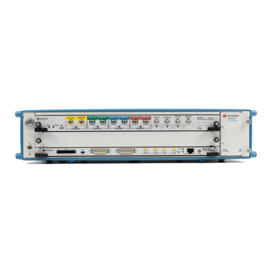
Page 21: The Front Panel Of The M8195A Rev 2
TRIG IN The Trigger Input has a combined functionality as Trigger or Gate and is used to start the M8195A by an external signal. This input is defined in detail in the chapter Sequencing EVENT IN The Event Input (EVENT IN) is used to e.g. -
Page 22: Status Led
Represents the state ‘Disable’. Selectable from SFP or SCPI. The output amplifier is not powered After Power-On the LED is off. After successful initialization of the M8195A, the LED turns to its default state which is OFF. ON, green Output enabled Represents the state ‘Enable’. -
Page 23: Trigger In And Event In Led
The LED turns On red in case a set-up or a hold time violation has been detected. Note A ‘Force Trigger’ from the SFP or SCPI does not turn the LED ON Keysight M8195A Revision 2 – Arbitrary Waveform Generator User’s Guide... -
Page 24: Ref Clk In Led
Ref CLK In has been selected as the clock reference The externally applied clock signal is not valid. E.g. the frequency does not match the adjusted value or the amplitude is outside the specified range Keysight M8195A Revision 2 – Arbitrary Waveform Generator User’s Guide... -
Page 25: Theory Of Operation
4 * 16.25 GSa/s Trigger 16, 32 or GSa/s 64 tap 16, 32 or GSa/s 64 tap 2 of the 4 may be designated as markers Figure 3: M8195A block diagram Keysight M8195A Revision 2 – Arbitrary Waveform Generator User’s Guide... - Page 26 1 Introduction The M8195A can operate in different modes: ‘Single Channel’, ‘Single Channel with markers’, ‘Dual Channel’, ‘Dual Channel Duplicate’, ‘Dual Channel with markers’, or ‘Four Channel’ There are two different memory modes available: ‘Internal’ and ‘Extended’. The memory mode is configurable for each channel.
- Page 27 = user programmable coefficient Figure 4: M8195A FIR filter operation with different dividers. Note: Sample rates are shown as 64, 32 and 16 GSa/s in the diagram. In fact, they are adjustable in the range: 53.76 … 65; 26.88 … 32.5 and 13.44 … 16.25 GSa/s...
-
Page 28: Timing Block Diagram
The level of detail is chosen to provide a general high level understanding of how the instrument is working. Therefore, not all of ports are shown in the above diagram. Keysight M8195A Revision 2 – Arbitrary Waveform Generator User’s Guide... - Page 29 DAC sample frequency references to a clock, the unit of the sample frequency is Hz. DAC Sample CLK: The DAC Sample CLK is the clock signal that sources the four DAC of the M8195A. There is a variable delay element between the clock generation block and the DAC.
-
Page 30: Delay Adjust
Ref Clk out. In case the M8195A is sourced from Ref CLk In (or the AXIe backplane), Data Out1, Data Out 2, Data Out 3, and Data Out 4 are delayed by 10 ps with respect to Ref CLk In (or the AXIe backplane). -
Page 31: Extended Memory Configuration
256 parallel samples is used to source up to 4 channels. The selected extended memory configuration is exclusive, mixed modes are not possible. Keysight M8195A Revision 2 – Arbitrary Waveform Generator User’s Guide... - Page 32 1, 2 or 4. This generates output vectors with a width of 256, 128 or 64 samples. This vector size is called waveform granularity and is the number of samples per channel processed within one sync clock cycle. Keysight M8195A Revision 2 – Arbitrary Waveform Generator User’s Guide...
-
Page 33: Instrument Modes
Ch 2: Inactive With -16G: or 13.44…16.25 GSa/s Ch 3: Marker 1 16 GSa @ 53.76...65 GSa/s Ch 4: Marker 2 8 GSa @ 26.88…32.5 GSa/s 4 GSa @ 13.44…16.25 GSa/s Keysight M8195A Revision 2 – Arbitrary Waveform Generator User’s Guide... - Page 34 Ch 4: Waveform 2 1GSa per channel. or 13.44…16.25 GSa/s Ch 3: Marker 1 With -16G: Ch 4: Marker 2 8 GSa @ 26.88…32.5 GSa/s 4 GSa @13.44…16.25 GSa/s per channel Keysight M8195A Revision 2 – Arbitrary Waveform Generator User’s Guide...
- Page 35 Ch 1: Waveform 1 Extended Memory 2 Ch 2: Waveform 2 No -16G: 0.5GSa/ch 13.44…16.25 GSa/s Extended Memory 3 Ch 3: Waveform 3 With -16G: 4GSa/ch Extended Memory 4 Ch 4: Waveform 4 Keysight M8195A Revision 2 – Arbitrary Waveform Generator User’s Guide...
-
Page 37: M8195A User Interface
Keysight M8195A Revision 2 – Arbitrary Waveform Generator User’s Guide M8195A User Interface Introduction Launching the M8195A Soft Front Panel M8195A User Interface Overview Driver Call Log Errors List Window Clock Tab Output Tab Trigger Tab FIR Filter Tab 2.10 Standard Waveform Tab 2.11... -
Page 38: Launching The M8195A Soft Front Panel
Launching the M8195A Soft Front Panel There are three ways to launch the M8195A Soft Front Panel: Select Start > All Programs > Keysight M8195 > Keysight M8195 Soft Front Panel from the Start Menu. From the Keysight Connection Expert select the discovered M8195 module, right-click to open the context menu and select “Send Commands To This... - Page 39 The instrument selection dialog shows the addresses of the discovered M8195A modules. Select a module from the list and press “Connect”. If no M8195A module is connected to your PC, you can check “Simulation Mode” to simulate an M8195A module.
-
Page 40: M8195A User Interface Overview
The menu bar includes the following pull down menu: File View Utilities Tools Help Each menu and its options are described in the following sections. Keysight M8195A Revision 2 – Arbitrary Waveform Generator User’s Guide... -
Page 41: Tools Menu
Opens a window to start the self-test and display the result after completion. 2.3.2.4 Tools Menu The Tools menu includes the following selections: Tools – Monitor Driver Calls Opens the Driver Call Log window. Keysight M8195A Revision 2 – Arbitrary Waveform Generator User’s Guide... -
Page 42: Clock/Output/Trigger/Fir Filter/Standard Waveform/Multi-Tone Waveform/Complex Modulated Waveform/Serial Data Waveform/Import Waveform/Sequence/Control Tabs
Waveform/Complex Modulated Waveform/Serial Data Waveform/Import Waveform/Sequence/Control Tabs These tabs are used to configure the most important parameters of the M8195A module. They are described in detail in the sections that follow. Keysight M8195A Revision 2 – Arbitrary Waveform Generator User’s Guide... -
Page 43: Numeric Control Usage
"E", and omit any trailing zeroes. For example, in the Frequency control you can type 2.5e+9 and press [Enter] to set the frequency to 2.5 GHz. (The plus sign is automatically inserted if it is omitted.) Keysight M8195A Revision 2 – Arbitrary Waveform Generator User’s Guide... -
Page 44: Driver Call Log
It has the following buttons: Save As… Saves the Driver Call Log as a text file. Clear History Clears the Driver Call Log. Close Exits the window. Keysight M8195A Revision 2 – Arbitrary Waveform Generator User’s Guide... -
Page 45: Errors List Window
M8195A User Interface 2 Errors List Window Use this window to view errors, warnings, and information. Figure 12: Errors list window Keysight M8195A Revision 2 – Arbitrary Waveform Generator User’s Guide... - Page 46 Description This column provides the description of individual errors. (Window Controls) This drop down list provides window control options like: Float Dock Auto Hide Close Keysight M8195A Revision 2 – Arbitrary Waveform Generator User’s Guide...
-
Page 47: Clock Tab
M8195A User Interface 2 Clock Tab Use this tab to configure the sample clock and the reference clock of M8195A module. The sample clock for all four Digital to Analog Converters (DAC) of the four channels is identical. It allows user to configure clock source, reference clock range and frequency, and DAC sample frequency. - Page 48 These two switches allow selecting reference clock out source depending on reference clock input source. Frequency Dividers There are in total five frequency dividers in the path to the Reference Clock Out. Three of them can be changed. Keysight M8195A Revision 2 – Arbitrary Waveform Generator User’s Guide...
-
Page 49: Output Tab
FIR filters are used as interpolation filters by factors of two or four. The interpolation is necessary as the DAC always operates in the range 53.76 GSa/s … 65 GSa/s. Keysight M8195A Revision 2 – Arbitrary Waveform Generator User’s Guide... - Page 50 2 M8195A User Interface Figure 14: Output tab Keysight M8195A Revision 2 – Arbitrary Waveform Generator User’s Guide...
- Page 51 Shows the currently active scaling factor. This parameter can be adjusted in the FIR filter tab. Scaled Amplitude Shows the effective output amplitude after the ‘FIR Scale’ had been applied. Keysight M8195A Revision 2 – Arbitrary Waveform Generator User’s Guide...
-
Page 52: Trigger Tab
2 M8195A User Interface Trigger Tab Use this tab to configure the trigger and event input parameters. It allows user to send software triggers and events to the module. Figure 15: Trigger tab Keysight M8195A Revision 2 – Arbitrary Waveform Generator User’s Guide... - Page 53 Use this button to send a software trigger to a channel. Force Event Use this button to send a software event to a channel. Force Enable Use this button to send a software “enable” to a channel. Keysight M8195A Revision 2 – Arbitrary Waveform Generator User’s Guide...
-
Page 54: Fir Filter Tab
For sample rate divider 1, 2, and 4 the number of coefficients are 16, 32, and 64, respectively. For complete details, refer to the section “Theory of Operation”. Figure 16: FIR Filter tab Keysight M8195A Revision 2 – Arbitrary Waveform Generator User’s Guide... - Page 55 “Send To Instrument" is pressed. Reset Coefficients This button resets the coefficient values for a certain channel to default. Send To Instrument This button sends the coefficient values to the instrument. Keysight M8195A Revision 2 – Arbitrary Waveform Generator User’s Guide...
- Page 56 FIR filter scaling factor for a channel.. The range is between 0 and 1. FIR Delay FIR filter delay for a channel.. The delay is only adjustable for the filter types ‘Lowpass’, ‘Nyquist’, and ‘Linear Interpolation’. Keysight M8195A Revision 2 – Arbitrary Waveform Generator User’s Guide...
-
Page 57: Standard Waveform Tab
Figure 17: Standard waveform tab Keysight M8195A Revision 2 – Arbitrary Waveform Generator User’s Guide... - Page 58 Noise Bandwidth parameters can be defined for this waveform type using the corresponding controls. If the Generate I/Q checkbox is checked, two uncorrelated noise waveforms will be assigned to the I and Q components. Keysight M8195A Revision 2 – Arbitrary Waveform Generator User’s Guide...
- Page 59 (random samples with a Gaussian distribution sampled at the DAC Sample Rate). For IQ modes, noise bandwidth around the carrier frequency will be twice this parameter. Keysight M8195A Revision 2 – Arbitrary Waveform Generator User’s Guide...
- Page 60 Set WL to Max. This check box forces the usage of the number of samples defined in the “Max. Wfm. Length” numeric entry field. Some waveform parameters may be adjusted to make sure that continuous play-back of the waveform is seamless. Keysight M8195A Revision 2 – Arbitrary Waveform Generator User’s Guide...
- Page 61 If set to a higher level than DAC Max, this will be automatically set to the same level. Acceptable range for this parameter is -1/+1, being the full dynamic range of the instrument’s DAC. Keysight M8195A Revision 2 – Arbitrary Waveform Generator User’s Guide...
- Page 62 The previous running status for the target instrument will be preserved but sampling rate may be modified depending on the waveform requirements. Set Defaults All the standard waveform parameters are set automatically to their corresponding default values. Keysight M8195A Revision 2 – Arbitrary Waveform Generator User’s Guide...
-
Page 63: Multi-Tone Waveform Tab
Figure 18: Multi-Tone waveform tab Keysight M8195A Revision 2 – Arbitrary Waveform Generator User’s Guide... - Page 64 It improves flatness and linear phase distortion. Standard Cable This checkbox activates the application of correction factors based on a typical high-quality, high-bandwidth 0.85m microwave cable (Huber+Suhner type M8041-61616). Keysight M8195A Revision 2 – Arbitrary Waveform Generator User’s Guide...
- Page 65 (Segment selection) and deactivated (None selection). Ch. 4 (Marker 2) Marker 2 is output on Channel 4. Signaling the beginning of each segment may be activated (Segment selection) and deactivated (None selection). Keysight M8195A Revision 2 – Arbitrary Waveform Generator User’s Guide...
- Page 66 Spacing = (Stop Frequency – Start Frequency)/(# of Tones – 1). # of Tones It is the total number of tones in the Multi-Tone signal including the ones in the notch, if any. Keysight M8195A Revision 2 – Arbitrary Waveform Generator User’s Guide...
- Page 67 (0.0 dB for Amplitude and 0.0 degrees for Phase). Keysight M8195A Revision 2 – Arbitrary Waveform Generator User’s Guide...
- Page 68 2 M8195A User Interface Figure 19: Multi-Tone waveform tab, arbitrary tone distribution Keysight M8195A Revision 2 – Arbitrary Waveform Generator User’s Guide...
-
Page 69: Complex Modulated Waveform Tab
(time, frequency, and modulation), even if the signal is generated in looped mode. Keysight M8195A Revision 2 – Arbitrary Waveform Generator User’s Guide... - Page 70 (in the 1st Nyquist Band) in the frequency domain. It also reverses the effect of any correction so correction factors obtained for the second Nyquist band will be applied appropriately. Keysight M8195A Revision 2 – Arbitrary Waveform Generator User’s Guide...
- Page 71 Pulse Shaping This drop-down list can select different pulse shaping to be applied to the baseband symbols; choices are ‘Root Raised Cosine’, ‘Raised Cosine’, ‘Gaussian’, ‘Rectangular’, ‘None‘, ‘EDGE’, and ‘Half Sine’. Keysight M8195A Revision 2 – Arbitrary Waveform Generator User’s Guide...
- Page 72 Channel Specific Frequency and Phase Response This checkbox activates the application of corrections based on frequency- domain calibration data stored in the target instrument in non-volatile memory. It improves flatness and linear phase distortions. Keysight M8195A Revision 2 – Arbitrary Waveform Generator User’s Guide...
- Page 73 If set to a higher level than DAC Max, this will be automatically set to the same level. Acceptable range for this parameter is -1/+1, being the full dynamic range of the instrument’s DAC. Keysight M8195A Revision 2 – Arbitrary Waveform Generator User’s Guide...
- Page 74 All the waveform parameters are set automatically to their corresponding default values. Abort This button allows canceling signal calculation at any moment. It only shows up during signal compilation. Keysight M8195A Revision 2 – Arbitrary Waveform Generator User’s Guide...
- Page 75 Comments must start with the ‘//’ character sequence and may use a complete line or be located at the end of any valid line (including the first line). Empty lines are also valid. Keysight M8195A Revision 2 – Arbitrary Waveform Generator User’s Guide...
- Page 76 The above file does not include any unnecessary line in the header as it defines a non- rotating, non-offset modulation so default values for these fields are used instead. The resulting constellation after loading this file is shown as following: Keysight M8195A Revision 2 – Arbitrary Waveform Generator User’s Guide...
- Page 77 -0.95, 0.95 -1.05, -1.05 0.95, -0.95 The above file includes a line to indicate that this is an offset modulation. The resulting constellation after loading this file is shown as following: Keysight M8195A Revision 2 – Arbitrary Waveform Generator User’s Guide...
- Page 78 10.0’) in a continuous fashion (‘RotMODE, cont’). In fact, the ‘Offset’ and ‘RotMode’ fields could be removed without any effect on the final signal as these fields take the default values. The resulting constellation after loading this file is shown as following: Keysight M8195A Revision 2 – Arbitrary Waveform Generator User’s Guide...
-
Page 79: Serial Data Waveform Tab
(time, frequency, and modulation), even if the signal is generated in looped mode. Keysight M8195A Revision 2 – Arbitrary Waveform Generator User’s Guide... - Page 80 ‘extended’ memory. The segment range is 1 to 16777216. For channels sourced from ‘Internal’ memory, the segment is always set to 1, and it displays the text ‘Internal’. Keysight M8195A Revision 2 – Arbitrary Waveform Generator User’s Guide...
- Page 81 ‘Raised Cosine’ and ‘Root Raised Cosine’ (Square Root Raised Cosine).‘ Notes: The default edge shape is ‘Gaussian’. For clock signals (i.e. the Clock Toggle button is set to ‘C/2’ or ‘C/4’) the edge shape is always Gaussian. Keysight M8195A Revision 2 – Arbitrary Waveform Generator User’s Guide...
- Page 82 The shift added to each channel may be calculated (in bits) for each channel using the expression Shift = (Channel Number -1) * (Seq. Shift). Unshifted PRBS sequences always start with the longest run of ‘1’ for that particular sequence. Keysight M8195A Revision 2 – Arbitrary Waveform Generator User’s Guide...
- Page 83 = 1 to maximize the nominal bandwidth for a given bitrate. The 89600 software must be set up to analyze a BPSK signal with the same baud rate and baseband filter characteristics. Keysight M8195A Revision 2 – Arbitrary Waveform Generator User’s Guide...
- Page 84 Comp #: This combo box allows the selection of any of the ten components (1- 10) for edition. The rest of the controls in this section will be referred, then, to Keysight M8195A Revision 2 – Arbitrary Waveform Generator User’s Guide...
- Page 85 The result can be observed by executing spectral jitter analysis in some jitter analysis tool such as the Keysight EZJIT. Amplitude: This is the rms (root-mean square) amplitude of the random jitter (1 sigma) and is expressed in Unit Intervals (UI).
- Page 86 Crest Factor: This parameter is expressed in dB relative to the rms amplitude of the noise. If the combined waveform (signal + noise) goes beyond the valid lower and upper limits, samples are clipped to the corresponding limit. The Keysight M8195A Revision 2 – Arbitrary Waveform Generator User’s Guide...
- Page 87 Slope: ISI filter is modeled as a linear attenuation slope, expressed in dB, so it can be fully defined by setting up the filter’s slope and is expressed in dB/GHz units. Keysight M8195A Revision 2 – Arbitrary Waveform Generator User’s Guide...
- Page 88 Definitions for tap levels are derived from the N4916B De-emphasis Signal Converter data sheet (see http://literature.cdn.keysight.com/litweb/pdf/5990-4630EN.pdf). Keysight M8195A Revision 2 – Arbitrary Waveform Generator User’s Guide...
- Page 89 PRBS sequences except when the “Set WL to Max” is checked. In this case the number of symbols in the resulting waveform will be the closest integer for the Keysight M8195A Revision 2 – Arbitrary Waveform Generator User’s Guide...
- Page 90 All the waveform parameters are set automatically to their corresponding default values. Abort This button allows canceling signal calculation at any moment. It only shows up during signal compilation. Keysight M8195A Revision 2 – Arbitrary Waveform Generator User’s Guide...
-
Page 91: Bitmapping For Binary Data To Pam Signals
The level number n is associated with the high level. Table 10: PAM4 Level number Binary data (‘Inverted’ not checked) Binary data (‘Inverted’ checked) Table 11: PAM8 Level number Binary data (‘Inverted’ not checked) Binary data (‘Inverted’ checked) Keysight M8195A Revision 2 – Arbitrary Waveform Generator User’s Guide... - Page 92 10 (or 12), direct mapping is applied. If the value is equal to or greater than 10 (or 12), random mapping is applied to any of the valid 10 (or 12) levels. Keysight M8195A Revision 2 – Arbitrary Waveform Generator User’s Guide...
-
Page 93: Import Waveform Tab
Import Waveform Tab Use this tab to perform the functions such as importing, scaling, and resampling waveform files in a variety of formats for their generation by the M8195A arbitrary waveform generator. It provides the controls which allow the complete definition of signal processing parameters for the waveform file format (For details, see Description). - Page 94 These files can be simply imported using the Input File section and can be sent to the instrument to view the waveform preview. The sample waveform data can be found at the location: Start > All Programs > Keysight M8195 > Keysight M8195 Examples The following are the steps to view the sample data file waveform preview: Select the Show Next Waveform Preview check box.
- Page 95 If the file contains multiple waveforms (file types MAT89600 and CSV), they can be sent to multiple channels in one operation. Keysight M8195A Revision 2 – Arbitrary Waveform Generator User’s Guide...
- Page 96 Name of column Import and download to M8195A, when corresponding channel box is checked Ch 1 Ch 4 ignored Ch 4, if Y2 is not present; ignored, if Y2 is present Keysight M8195A Revision 2 – Arbitrary Waveform Generator User’s Guide...
- Page 97 To meet the granularity conditions, a number of samples is removed until the resulting number of samples is a multiple of the Keysight M8195A Revision 2 – Arbitrary Waveform Generator User’s Guide...
- Page 98 DAC Max Imported waveforms may occupy a limited range of the DAC’s full scale. This parameter sets the maximum level. If set to a lower level than DAC Min, this Keysight M8195A Revision 2 – Arbitrary Waveform Generator User’s Guide...
- Page 99 The previous running status for the target instrument will be preserved but sampling rate may be modified depending on the waveform requirements. Set Defaults All the imported waveform parameters are set automatically to their corresponding default values. Keysight M8195A Revision 2 – Arbitrary Waveform Generator User’s Guide...
-
Page 100: Sequence/Control Tab
‘extended’ memory). The option ‘SEQ’ must be installed for sequencing to work. You can also configure various sequence/control parameters using this tab. The following figure shows Sequence/Control tab (STScenario mode): Figure 24: Sequence/Control tab (STScenario mode) Keysight M8195A Revision 2 – Arbitrary Waveform Generator User’s Guide... - Page 101 The following figure shows Sequence/Control tab (STSequence Mode with Dynamic Control on and signal generation started): Figure 26: Sequence/Control tab (STSequence mode with Dynamic Control on and Signal Generation started) Keysight M8195A Revision 2 – Arbitrary Waveform Generator User’s Guide...
- Page 102 Allows to select the next sequence to be played when dynamic control for segments or sequences is enabled. This option is available only if Arbitrary or STSequence mode is selected. Keysight M8195A Revision 2 – Arbitrary Waveform Generator User’s Guide...
- Page 103 After having received the next advancement event, the process is repeated until having executed all loops of the current element. Then the execution advances to the next element. Keysight M8195A Revision 2 – Arbitrary Waveform Generator User’s Guide...
- Page 104 Insert a new sequence entry row above the selected entry. (Insert Below) Insert a new sequence entry row below the selected entry. (Delete) Delete the selected sequence entries. Keysight M8195A Revision 2 – Arbitrary Waveform Generator User’s Guide...
- Page 105 Extract existing sequence configuration from the instrument. Licenses and Options Section Installed Options This field displays the installed options for the M8195A module. Installed Licenses This field displays the installed licenses for the M8195A module. Keysight M8195A Revision 2 – Arbitrary Waveform Generator User’s Guide...
-
Page 106: Correction File Format
‘y’ or ‘Y’ character. Entries in this section are made by Amp1(Fi), Phase1(Fi) pairs. In particular, this format is compatible with adaptive equalizer files exported in comma-separated value (CSV) format from the Keysight 89600 VSA software package. These files reflect the channel response corrected by the equalizer so they should be applied through the selection of the ‘Channel_Response’... - Page 107 ‘Generate IQ Data” checkbox setting so, as it happens with the correction of multi- tone baseband signals, the internal or external carrier frequency is represented by the central entry in the list. Keysight M8195A Revision 2 – Arbitrary Waveform Generator User’s Guide...
-
Page 109: Sequencing
Keysight M8195A Revision 2 – Arbitrary Waveform Generator User’s Guide Sequencing Introduction Sequencing Hierarchy Trigger Modes Arm Mode Advancement Modes Sequencer Controls Sequencer Execution Flow Sequencer Modes Dynamic Sequencing 3.10 Idle Command Segments 3.11 Limitations Introduction This chapter describes the sequencing capabilities of the instrument. -
Page 110: Option Sequencing For Extended Memory
For operation in instrument mode ‘Dual Channel’ or instrument mode ‘Four Channel’, all channels sourced from extended memory of M8195A behave identical with respect to sequencing. i.e. there is one sequence table available for the M8195A. Certainly the waveforms of the channels can be different for any segment number. -
Page 111: Sequencer Granularity
Therefore, the sequencer has to play multiple samples within one sync clock cycle. The number of samples played within one sync clock cycle is called waveform granularity or segment granularity. For details, refer to the block diagrams in section 1.5.4. Keysight M8195A Revision 2 – Arbitrary Waveform Generator User’s Guide... -
Page 112: Sequencing Hierarchy
Repeat Count 2 Repeat Count 3 Sequence Repeat Count (continuously or “n” times) Figure 28: Sequence A sequence can be played standalone (see Sequence Mode) or can be part of a scenario. Keysight M8195A Revision 2 – Arbitrary Waveform Generator User’s Guide... -
Page 113: Scenario
Alternatively, after having received a trigger, a waveform can also be played infinitely. See Sequencer Modes for more details. Keysight M8195A Revision 2 – Arbitrary Waveform Generator User’s Guide... -
Page 114: Gated
For more details, refer to the examples given in the section Sequencer Modes. Keysight M8195A Revision 2 – Arbitrary Waveform Generator User’s Guide... -
Page 115: Auto
Then the execution advances to the next element. Sequencer Controls Sequencer Controls are used to influence the sequencer. So they can control the waveform generation. Keysight M8195A Revision 2 – Arbitrary Waveform Generator User’s Guide... -
Page 116: External Inputs
External Inputs 3.6.1.1 TRIGGER/EVENT The M8195A accepts a wide range of external trigger signal levels to easily adapt to a measurement setup. The input threshold is user configurable along with the polarity or whether rising, falling or both edges are to be taken into account. Two modes of operation are available: Asynchronous and Synchronous triggering. - Page 117 DAC sampling rate divided by 8. This provides a more precise trigger/event to output latency without the need of providing the inputs synchronous to any reference. Keysight M8195A Revision 2 – Arbitrary Waveform Generator User’s Guide...
-
Page 118: Logical Functions
Then the stored advancement event is cleared and the instrument is able to receive the next one. Keysight M8195A Revision 2 – Arbitrary Waveform Generator User’s Guide... -
Page 119: Internal Trigger Generator
3.6.3 Internal Trigger Generator The M8195A provides a configurable internal trigger generator that allows for generation of a periodic trigger signal that is frequency locked to the clock of the sequencer engine. In Gated mode, the internal trigger generator provides a gate with a width of 50% of the trigger generator period. - Page 120 Dynamic control inputs are only available, when using the M8197A. Then in case of the dynamic control, the software controls have precedence unless the hardware inputs are explicitly disabled using the commands. See also chapter Trigger Tab. Keysight M8195A Revision 2 – Arbitrary Waveform Generator User’s Guide...
-
Page 121: Sequencer Execution Flow
Continuous, the enable signal is used to control the execution of the first segment or sequence. In trigger mode Gated or Triggered, the enable is used as an additional start input. Keysight M8195A Revision 2 – Arbitrary Waveform Generator User’s Guide... -
Page 122: Sequencer Modes
So the currently running segment/sequence or scenario is not completed before stopping. 3.8.1 Arbitrary Mode In Arbitrary Mode, a single segment is played. Segment Loop Count=4 Figure 31: Segment Keysight M8195A Revision 2 – Arbitrary Waveform Generator User’s Guide... - Page 123 Conditional: The segment is played infinitely after receiving a trigger. After being stopped (See SCPI command :ABORt[1|2|3|4]) the offset value is played. Offset Trigger Last Offset Value Trigger Stop (Abort) Figure 33: Segment advance = auto Keysight M8195A Revision 2 – Arbitrary Waveform Generator User’s Guide...
- Page 124 Offset Value Value Value Adv Event Adv Event Adv Event Stop Trigger (Abort) Figure 35: Segment advance = single Offset Offset Stop Trigger (Abort) Figure 36: Segment advance = conditional Keysight M8195A Revision 2 – Arbitrary Waveform Generator User’s Guide...
- Page 125 Later, changes of this signal are ignored. Trigger Mode Continuous Offset Offset Stop Enable (Abort) Figure 38: Trigger mode continuous Trigger Mode Triggered Last Offset Value Enable Trigger Trigger Figure 39: Trigger mode triggered Keysight M8195A Revision 2 – Arbitrary Waveform Generator User’s Guide...
- Page 126 3 Sequencing Trigger Mode Gated Last Offset Value Gate Enable Gate Gate Figure 40: Trigger Mode Gated Keysight M8195A Revision 2 – Arbitrary Waveform Generator User’s Guide...
-
Page 127: Sequence Mode
After programming, the sequence is started automatically and played infinitely. Continuous The following segment advancement modes are available: Auto Conditional (Advancement Event) Repeated (Advancement Event) Single (Advancement Event) Keysight M8195A Revision 2 – Arbitrary Waveform Generator User’s Guide... - Page 128 (See SCPI command :ABORt[1|2|3|4]) the offset value is played. The following segment advancement modes are available: Auto Conditional (Advancement Event) Repeat (Advancement Event) Single (Advancement Event) Keysight M8195A Revision 2 – Arbitrary Waveform Generator User’s Guide...
- Page 129 Adv Event Trigger Figure 43: Sequence advance = auto Offset Last Value Adv Event Trigger Last Value Adv Event Adv Event Adv Event Trigger Figure 44: Sequence advance = repeated Keysight M8195A Revision 2 – Arbitrary Waveform Generator User’s Guide...
- Page 130 Last Value Adv Event belongs to Trigger Segment Advance Last Value Adv Event belongs to Adv Event Adv Event Trigger Segment + Sequence Advance Figure 46: Sequence advancement = single Keysight M8195A Revision 2 – Arbitrary Waveform Generator User’s Guide...
- Page 131 Conditional (Advancement Event) Repeat (Advancement Event) Single (Advancement Event) Offset Last Value Adv Event Adv Event Gate Last Value Adv Event Gate Gate Adv Event Figure 47: Trigger mode gated Keysight M8195A Revision 2 – Arbitrary Waveform Generator User’s Guide...
- Page 132 The sequence is played infinitely until being stopped. After being restarted, the first segment is played until it receives an enable. Offset Adv Event Enable Last Value Adv Event Adv Event Stop Enable (Abort) Figure 48: Trigger mode continuous Keysight M8195A Revision 2 – Arbitrary Waveform Generator User’s Guide...
- Page 133 Behavior is like self armed with an additional ENABLE. The enable is evaluated only once at the beginning. Later changes of this signal are ignored. Last Offset Value Gate Gate Gate Enable Figure 50: Trigger mode gated Keysight M8195A Revision 2 – Arbitrary Waveform Generator User’s Guide...
-
Page 134: Scenario Mode
Trigger Mode Continuous After programming, the scenario is started automatically and played infinitely. The following segment/sequence advancement modes are available: Auto Conditional (Advancement Event) Repeat (Advancement Event) Single (Advancement Event) Keysight M8195A Revision 2 – Arbitrary Waveform Generator User’s Guide... - Page 135 (See SCPI command :ABORt[1|2|3|4]) the offset value is played. The following segment/sequence advancement modes are available: Auto Conditional (Advancement Event) Repeat (Advancement Event) Single (Advancement Event) Keysight M8195A Revision 2 – Arbitrary Waveform Generator User’s Guide...
- Page 136 Single (Advancement Event) The following scenario advancement mode is available: The scenario is played infinitely until being stopped. After being restarted, the first sequence is played until it receives an enable. Keysight M8195A Revision 2 – Arbitrary Waveform Generator User’s Guide...
- Page 137 Later changes of this signal are ignored. Trigger Mode Gated Behavior is like self armed with an additional ENABLE. The enable is evaluated only once at the beginning. Later changes of this signal are ignored. Keysight M8195A Revision 2 – Arbitrary Waveform Generator User’s Guide...
-
Page 138: Dynamic Sequencing
Create one segment with the content of all 6 segments. Put a loop count of 6 on the last segment. Use a segment of at least 256 vectors for the 6 segment. Keysight M8195A Revision 2 – Arbitrary Waveform Generator User’s Guide... -
Page 139: Dynamic Continuous
Due to instrument internal functionality, this delay cannot be specified exactly and it is always possible that one more segment/sequence A is played before switching to B. Change Delay Dynamic Change At Dynamic Port Figure 54: Dynamic continuous Keysight M8195A Revision 2 – Arbitrary Waveform Generator User’s Guide... -
Page 140: Dynamic Triggered
A is played before switching to B. Trigger Trigger Trigger Trigger Change Delay Dynamic Change At Dynamic Port Figure 55: Dynamic triggered Keysight M8195A Revision 2 – Arbitrary Waveform Generator User’s Guide... -
Page 141: Idle Command Segments
10 * segment vectors, loop count: up to 2^32) would provide an idle delay of more than 165 seconds in high speed mode at 64 GSa/s and should be sufficient for most applications. Keysight M8195A Revision 2 – Arbitrary Waveform Generator User’s Guide... -
Page 142: Limitations
The last adjacent segments in a sequence in sequence mode or the last adjacent segments in a scenario in scenario mode can be shorter than 257 sample vectors in total. Keysight M8195A Revision 2 – Arbitrary Waveform Generator User’s Guide... - Page 143 B is also bigger than 256 vectors. Segment C and D are placed next to each other and the resulting length is 260 vectors. The small segment E is placed in front of a big segment. Keysight M8195A Revision 2 – Arbitrary Waveform Generator User’s Guide...
-
Page 145: Introduction
This chapter describes the streaming capabilities of the M8195A. Introduction The streaming feature of the M8195A allows re-loading the sample memory while being in the run mode. This capability provides a method to generate waveforms with an infinite playtime. Streaming is supported by the Dynamic Mode. -
Page 146: Memory Ping-Pong
TRAC:DEF 1,1280 TRAC:DEF 2,1280 Create two sequence table entries referring to the waveform segments. :STAB:DATA 0, 0,1,1,1,0, #hFFFFFFFF :STAB:DATA 1, 0,1,1,2,0, #hFFFFFFFF Load first segment with data. :TRAC:DATA 1,0,#41280<data_bytes> Keysight M8195A Revision 2 – Arbitrary Waveform Generator User’s Guide... -
Page 147: Setup Example Using The Sfp
Sequence/Control Tab. Use the “Select Init Segment” field to select the waveform segment, that will be executed immediately after starting the signal generation. Send the sequence table to the M8195A. Start signal generation by pressing the Run/Stop button. Keysight M8195A Revision 2 – Arbitrary Waveform Generator User’s Guide... - Page 148 Waveform update and switch operation in a loop until stopped by pressing the Run/Stop button: Reload data into next segment using the Standard Waveform Tab. Dynamically switch to reloaded segment using the “Select Dyn Sequence” field in the Sequence/Control Tab. Keysight M8195A Revision 2 – Arbitrary Waveform Generator User’s Guide...
-
Page 149: Introduction
This means that each sample has its own bit signaling whether this sample is marked or not. The M8195A marker logic uses an edge based concept and therefore the sample based marker waveform is converted to an edge based marker waveform by the firmware of the instrument. -
Page 150: Limitations
The following drawing shows some examples of rising and falling marker edge positions. The distance is always more than 128 DAC samples. Marker Transition 127 128 255 256 383 384 Figure 59: Marker transition Keysight M8195A Revision 2 – Arbitrary Waveform Generator User’s Guide... - Page 151 In such case each portion is treated individually and rising or falling edges are automatically inserted at the beginning with the already mentioned limitations. Keysight M8195A Revision 2 – Arbitrary Waveform Generator User’s Guide...
-
Page 152: Sample Marker In Segments Which Are Addressed Offset Based
This needs to be taken into account by the user, when setting up markers. Keysight M8195A Revision 2 – Arbitrary Waveform Generator User’s Guide... -
Page 153: General Programming
Keysight M8195A Revision 2 – Arbitrary Waveform Generator User’s Guide General Programming Introduction IVI-COM Programming SCPI Programming Programming Recommendations System Related Commands (SYSTem Subsystem) Common Command List Status Model :ARM/TRIGger Subsystem :TRIGger - Trigger Input 6.10 :FORMat Subsystem 6.11 :INSTrument Subsystem 6.12... -
Page 154: Introduction
The following picture gives an overview about how things work together: Figure 60: M8195A programming The Soft Front Panel talks to the actual M8195A module using a PCI express or USB connection. I/O to the module is done using VISA library of Keysight I/O library. -
Page 155: Ivi-Com Programming
General Programming 6 IVI-COM Programming The recommended way to program the M8195A module is to use the IVI drivers. See documentation of the IVI drivers how to program using IVI drivers. The connection between the IVI-COM driver and the Soft Front Panel is hidden. To address a module therefore the PXI or USB resource string of the module is used. -
Page 156: Agm8195Sfp.exe
Before sending SCPI commands to the instrument, the Soft Front Panel (AgM8195SFP.exe) must be started. This can be done in the Windows Start menu (Start > All Programs > Keysight M8195 > Keysight M8195 Soft Front Panel). 6.3.1.1 Command Line Arguments... - Page 157 /Socket, /Telnet, /Inst, /HiSLIP or their respective default values instead. If both /NoAutoID and /AutoID are specified, /AutoID overrides /NoAutoID. The first port not assigned by IANA is 49152 (IANA, Internet Assigned Numbers Authority, http://www.iana.org) Keysight M8195A Revision 2 – Arbitrary Waveform Generator User’s Guide...
-
Page 158: Programming Recommendations
Sufficient to use: :VOLT M8195A is a 4 channel instrument. Parameters have to be specified for output 1, 2, 3, and 4. If there is no output specified the command will set the default output 1. So, for setting an offset of 10mV for output 1 and output 2 the commands are: # sets offset of 10mV at output 1 VOLT:OFFS 0.01... -
Page 159: System Related Commands (System Subsystem)
Trigger Out functionality is active, Event In functionality is disabled and vice versa. Note: Trigger Out is for future use. There are no plans to support Trigger Out functionality directly from M8195A firmware. Trigger Out is tentatively supported by 81195A optical modulation generator software (V2.1 or later). -
Page 160: System:help:headers
SCPI format. The short form uses uppercase characters while the additional characters for the long form are in lowercase characters. Default nodes are surrounded by square brackets ([]). Example Query :SYST:HELP:HEAD? Keysight M8195A Revision 2 – Arbitrary Waveform Generator User’s Guide... -
Page 161: System:license:extended:list
In set form, the block data must be a complete instrument set-up read using the query form of the command. This command has the same functionality as the *LRN command. Example Command :SYST:SET <binary block data> Query :SYST:SET? Keysight M8195A Revision 2 – Arbitrary Waveform Generator User’s Guide... -
Page 162: System:version
These queries return information about the instrument Soft Front Panel’s available connections. If a connection is not available, the returned value is -1. This is only useful if there is more than one Keysight module connected to a PC, otherwise one would normally use the default connections (HiSLIP and VXI-11 instrument number 0, socket port 5025, telnet port 5024) One can never be sure if a socket port is already in use, so one could e.g. - Page 163 Example Query :SYST:COMM:INST? 6.5.7.2 :SYSTem:COMMunicate:HISLip[:NUMBer]? Command :SYST:COMM:HISL? Long :SYSTem:COMMunicate:HISLip? Parameters None Parameter Suffix None Description This query returns the HiSLIP number used by the Soft Front Panel. Example Query :SYST:COMM:HISL? Keysight M8195A Revision 2 – Arbitrary Waveform Generator User’s Guide...
- Page 164 Example Query :SYST:COMM:SOCK? 6.5.7.4 :SYSTem:COMMunicate:TELNet[:PORT]? Command :SYST:COMM:TELN? Long :SYSTem:COMMunicate:TELNet? Parameters None Parameter Suffix None Description This query returns the telnet port used by the Soft Front Panel. Example Query :SYST:COMM:TELN? Keysight M8195A Revision 2 – Arbitrary Waveform Generator User’s Guide...
- Page 165 This query returns the port number of the control connection. You can use the control port to send control commands (for example “Device Clear”) to the instrument. Example Query :SYST:COMM:TCP:CONT? Keysight M8195A Revision 2 – Arbitrary Waveform Generator User’s Guide...
-
Page 166: Common Command List
6.6.5 *OPC Set the “Operation Complete” bit (bit 0) in the Standard Event register after the previous commands have been completed. Keysight M8195A Revision 2 – Arbitrary Waveform Generator User’s Guide... -
Page 167: Opc
Serial Poll but it is processed like any other instrument command. This command returns the same result as a Serial Poll but the “Master Summary” bit (bit 6) is not cleared by the *STB? command. Keysight M8195A Revision 2 – Arbitrary Waveform Generator User’s Guide... -
Page 168: Tst
Use to send the learn string. :SYST:SET See :SYSTem:SET[?]. 6.6.13 *WAI? Prevents the instrument from executing any further commands until the current command has finished executing. Keysight M8195A Revision 2 – Arbitrary Waveform Generator User’s Guide... -
Page 169: Status Model
Status Model Introduction This section describes the structure of the SCPI status system used by the M8195A. The status system records various conditions and states of the instrument in several register groups as shown on the following pages. Each of the register groups is made up of several low level registers called Condition registers, Event registers, and Enable registers which control the action of specific bits within the register group. - Page 170 6 General Programming Figure 61: Status register structure Keysight M8195A Revision 2 – Arbitrary Waveform Generator User’s Guide...
-
Page 171: Status:preset
One or more bits are set in the Standard Event Register Master Summary One or more bits are set in the Status Byte Register Operational Data One or more bits set in the Operation Data Register (bits must be enabled) Keysight M8195A Revision 2 – Arbitrary Waveform Generator User’s Guide... -
Page 172: Questionable Data Register Command Subsystem
Sequence generation errors happened Not used 2048 Returns “0” DUC Status 4096 Amplitude has been clipped after DUC Not used 8192 Returns “0” Not used 16384 Returns “0” Not used 32768 Returns “0” Keysight M8195A Revision 2 – Arbitrary Waveform Generator User’s Guide... - Page 173 Setting both positive/negative filters true allows an event to be reported anytime the condition changes. Clearing both filters disable event reporting. The contents of transition filters are unchanged by *CLS and *RST. Keysight M8195A Revision 2 – Arbitrary Waveform Generator User’s Guide...
-
Page 174: Operation Status Subsystem
Not used 1024 Returns “0” Not used 2048 Returns “0” Not used 4096 Returns “0” Not used 8192 Returns “0” Not used 16384 Returns “0” Not used 32768 Returns “0” Keysight M8195A Revision 2 – Arbitrary Waveform Generator User’s Guide... - Page 175 Setting both positive/negative filters true allows an event to be reported anytime the condition changes. Clearing both filters disable event reporting. The contents of transition filters are unchanged by *CLS and *RST. Keysight M8195A Revision 2 – Arbitrary Waveform Generator User’s Guide...
-
Page 176: Voltage Status Subsystem
The amplitude for output 3 has been clipped to the highest/lowest possible DAC value. Amplitude clipped The amplitude for output 4 has been clipped to the highest/lowest possible DAC value. Keysight M8195A Revision 2 – Arbitrary Waveform Generator User’s Guide... -
Page 177: Frequency Status Subsystem
:STATus:QUEStionable:SEQuence:CONDition? :STATus:QUEStionable:SEQuence:ENABle[?] :STATus:QUEStionable:SEQuence:NTRansition[?] :STATus:QUEStionable:SEQuence:PTRansition[?] Table 27: Sequence status register Bit Number Decimal Value Definition 0 Sequence data error Sequence has errors 1 Sequence linear-playtime error Sequence has a linear-playtime error Keysight M8195A Revision 2 – Arbitrary Waveform Generator User’s Guide... -
Page 178: Duc Status Subsystem
M8195A module. The following SCPI commands and queries are supported: :STATus:QUEStionable:CONNection[:EVENt]? :STATus:QUEStionable:CONNection:CONDition? :STATus:QUEStionable:CONNection:ENABle[?] :STATus:QUEStionable:CONNection:NTRansition[?] :STATus:QUEStionable:CONNection:PTRansition[?] Table 29: Connection status register Bit Number Decimal Value Definition USB disconnected USB module connection state Keysight M8195A Revision 2 – Arbitrary Waveform Generator User’s Guide... -
Page 179: Run Status Subsystem
Indicates if channel 1 is running Run Status Indicates if channel 2 is running Run Status Indicates if channel 3 is running Run Status Indicates if channel 4 is running Keysight M8195A Revision 2 – Arbitrary Waveform Generator User’s Guide... -
Page 180: Arm/Trigger Subsystem
{<delay> | MINimum | MAXimum} Parameter Suffix [s|ms|us|ns|ps] Description Set or query the module delay settings (see section 1.5.3) . The unit is in seconds. Example Command :ARM:MDEL 1E-13 Query :ARM:MDEL? Keysight M8195A Revision 2 – Arbitrary Waveform Generator User’s Guide... -
Page 181: Arm[:Sequence][:Start][:Layer]:Sdelay[1|2|3|4][?]
Command :ARM:SDEL 10 Query :ARM:SDEL? 6.8.4 :INITiate:CONTinuous:ENABle[?] SELF|ARMed Command :INIT:CONT:ENAB[?] Long :INITiate:CONTinuous:ENABle[?] Parameters SELF|ARMed Parameter Suffix None Description Set or query the arming mode. Example Command :INIT:CONT:ENAB SELF Query :INIT:CONT:ENAB? Keysight M8195A Revision 2 – Arbitrary Waveform Generator User’s Guide...|Minimum|Maximum -
Page 182: Initiate:continous[:State][?] Off
“triggered”, else it is “gated”. 1/ON – Continuous mode is on. Trigger mode is “automatic”. The value of gate mode is not relevant. Example Command :INIT:CONT:STAT ON Query :INIT:CONT:STAT? Keysight M8195A Revision 2 – Arbitrary Waveform Generator User’s Guide... -
Page 183: Initiate:gate[:State][?] Off
1/ON – Gate mode is on. If continuous mode is off, the trigger mode is “gated”. Example Command :INIT:GATE:STAT ON Query :INIT:GATE:STAT? Table 31: Trigger mode settings INIT:CONT INIT:GATE Trigger Mode Triggered Gated Continuous Continuous Keysight M8195A Revision 2 – Arbitrary Waveform Generator User’s Guide... -
Page 184: Initiate:immediate[1|2|3|4]
Command :ARM:TRIG:LEV[?] Long :ARM:TRIGger:LEVel[?] Parameters <level>|MINimum|MAXimum Parameter Suffix None Description Set or query the trigger input threshold level. <level> – Threshold level voltage. Example Command :ARM:TRIG:LEV 3e-9 Query :ARM:TRIG:LEV? Keysight M8195A Revision 2 – Arbitrary Waveform Generator User’s Guide... -
Page 185: Arm[:Sequence][:Start][:Layer]:Trigger:slope[?] Positive|Negative|Either
Parameter Suffix None Description Set or query the trigger input slope. POSitive – rising edge NEGative – falling edge EITHer – both Example Command :ARM:TRIG:SLOP POS Query :ARM:TRIG:SLOP? Keysight M8195A Revision 2 – Arbitrary Waveform Generator User’s Guide... -
Page 186: Arm[:Sequence][:Start][:Layer]:Trigger:source[?] Trigger|Event|Internal
Long :ARM:TRIGger:FREQuency[?] Parameters <frequency>|MINimum|MAXimum Parameter Suffix None Description Set or query the frequency of the internal trigger generator. <frequency> – internal trigger frequency Example Command :ARM:TRIG:FREQ 1 Query :ARM:TRIG:FREQ? Keysight M8195A Revision 2 – Arbitrary Waveform Generator User’s Guide... -
Page 187: Arm[:Sequence][:Start][:Layer]:Trigger:operation[?] Asynchronous|Synchronous
:ARM[:SEQuence][:STARt][:LAYer]:EVENt:LEVel[?] <level>|MINimum|MAXimum Command :ARM:EVEN:LEV[?] Long :ARM:EVENt:LEVel[?] Parameters <level>|MINimum|MAXimum Parameter Suffix None Description Set or query the input threshold level. <level> – Threshold level voltage. Example Command :ARM:EVEN:LEV 2e-9 Query :ARM:EVEN:LEV? Keysight M8195A Revision 2 – Arbitrary Waveform Generator User’s Guide... -
Page 188: Arm[:Sequence][:Start][:Layer]:Event:slope[?] Positive|Negative|Either
TRIGger|EVENt Parameter Suffix None Description Set or query the source for the enable event. TRIGger - trigger input EVENt - event input Example Command :TRIG:SOUR:ENAB TRIG Query :TRIG:SOUR:ENAB? Keysight M8195A Revision 2 – Arbitrary Waveform Generator User’s Guide... -
Page 189: Trigger[:Sequence][:Start]:Enable:hwdisable[:State][?] 0|1|Off|On
:TRIGger[:SEQuence][:STARt]:BEGin[:IMMediate] command. When the hardware input is enabled, a trigger can be generated by command, by a signal present at the trigger input or the internal trigger generator. Keysight M8195A Revision 2 – Arbitrary Waveform Generator User’s Guide... -
Page 190: Trigger[:Sequence][:Start]:Advance:hwdisable[:State][?] 0|1|Off|On
:TRIGger[:SEQuence][:STARt]:ADVance[:IMMediate] command. When the hardware input is enabled, an advancement event can be generated by command or by a signal present at the trigger or event input. Example Command :TRIG:ADV:HWD 0 Query :TRIG:ADV:HWD? Keysight M8195A Revision 2 – Arbitrary Waveform Generator User’s Guide... -
Page 191: Trigger - Trigger Input
INTernal – internal trigger generator Example Command :TRIG:SOUR:ADV TRIG Query :TRIG:SOUR:ADV? 6.9.2 :TRIGger[:SEQuence][:STARt]:ENABle[:IMMediate] Command :TRIG:ENAB Long :TRIGger:ENABle Parameters None Parameter Suffix None Description Send the enable event to a channel. Example Command :TRIG:ENAB Keysight M8195A Revision 2 – Arbitrary Waveform Generator User’s Guide... -
Page 192: Trigger[:Sequence][:Start]:Begin[:Immediate]
:TRIG:BEG:GATE[?] Long :TRIGger:BEGin:GATE[?] Parameters OFF|ON|0|1 Parameter Suffix None Description In gated mode send a “gate open” (ON|1) or “gate close” (OFF|0) to a channel. Example Command :TRIG:BEG:GATE ON Query :TRIG:BEG:GATE? Keysight M8195A Revision 2 – Arbitrary Waveform Generator User’s Guide... -
Page 193: Trigger[:Sequence][:Start]:Advance[:Immediate]
General Programming 6 6.9.5 :TRIGger[:SEQuence][:STARt]:ADVance[:IMMediate] Command :TRIG:ADV Long :TRIGger:ADVance Parameters None Parameter Suffix None Description Send the advancement event to a channel. Example Command :TRIG:ADV Keysight M8195A Revision 2 – Arbitrary Waveform Generator User’s Guide... -
Page 194: Format Subsystem
Byte ORDer. Controls whether binary data is transferred in normal (“big endian”) or swapped (“little endian”) byte order. Affects [:SOURce]:STABle:DATA, OUTPut:FILTer:FRATe, OUTPut:FILTer:HRATe and OUTPut:FILTer:QRATe. Example Command :FORM:BORD NORM Query :FORM:BORD? Keysight M8195A Revision 2 – Arbitrary Waveform Generator User’s Guide... -
Page 195: Instrument Subsystem
Identify the instrument by flashing the green “Access” LED on the front panel for a certain time. <seconds> - optional length of the flashing interval, default is 10 seconds. Example Command :INST:IDEN 5 Keysight M8195A Revision 2 – Arbitrary Waveform Generator User’s Guide... -
Page 196: Instrument:identify:stop
Stop the flashing of the green “Access” LED before the flashing interval has elapsed. Example Command :INST:IDEN:STOP 6.11.4 :INSTrument: HWRevision? Command :INST:HWR? Long :INSTrument:HWRevision? Parameters None Parameter Suffix None Description Returns the M8195A hardware revision number. Example Query :INST:HWR? Keysight M8195A Revision 2 – Arbitrary Waveform Generator User’s Guide... -
Page 197: Instrument:dacmode[?] Single|Dual|Four|Marker|Dcduplicate|Dcmarker
MARKer or DCMarker the data loaded to channel 1 consists of interleaved 1-byte waveform and 1-byte marker samples (see section :TRACe Subsystem). In operation mode DDUPlicate waveforms can only be loaded to channels 1 and 2. Example Command :INST:DACM DUAL Keysight M8195A Revision 2 – Arbitrary Waveform Generator User’s Guide... -
Page 198: Instrument:memory:extended:rdivider [?] Div1|Div2|Div4
:INST:MEM:EXT:RDIV? 6.11.7 :INSTrument:MMODule:CONFig? Command :INST:MMOD:CONF? Long :INSTrument:MMODule:CONFig? Parameters None Parameter Suffix None Description This query returns the state of the multi-module configuration mode (0: disabled, 1: enabled). Example Query :INST:MMOD:CONF? Keysight M8195A Revision 2 – Arbitrary Waveform Generator User’s Guide... -
Page 199: Instrument:mmodule:mode
This query returns the multi-module mode. NORMal – Module does not belong to a multi-module group. SLAVe – Module is a slave in a multi-module group Example Query :INST:MMOD:MODE? Keysight M8195A Revision 2 – Arbitrary Waveform Generator User’s Guide... -
Page 200: Mmemory Subsystem
<file_size> provides the size of the file in bytes. In case of directories, <file_entry> is surrounded by square brackets and both <file_type> and <file_size> are empty. Example Query :MMEM:CAT? Keysight M8195A Revision 2 – Arbitrary Waveform Generator User’s Guide... -
Page 201: Mmemory:cdirectory [
At *RST, this value is set to the default user data storage area, that is defined as System.Environment.SpecialFolder.Personal e.g. C:\Users\Name\Documents MMEMory:CDIRectory? — Query returns full path of the default directory. Example Command :MMEM:CDIR “C:\Users\Name\Documents” Query :MMEM:CDIR? Keysight M8195A Revision 2 – Arbitrary Waveform Generator User’s Guide...] -
Page 202: Mmemory:copy
The second pair specifies the destination. An error is generated if the source doesn't exist or the destination file already exists. Example Command :MMEM:COPY "C:\data.txt", "C:\data_new.txt" Keysight M8195A Revision 2 – Arbitrary Waveform Generator User’s Guide..., [, , ] -
Page 203: Mmemory:delete
None Description The command form is MMEMory:DATA <file_name>,<data>. It loads <data> into the file <file_name>. <data> is in 488.2 block format. <file_name> is string data. Example Command :MMEM:DATA “C:\data.txt”, #14test Keysight M8195A Revision 2 – Arbitrary Waveform Generator User’s Guide...[, ] -
Page 204: Mmemory:data?
6.12.7 :MMEMory:MDIRectory <directory_name> Command :MMEM:MDIR Long :MMEMory:MDIRectory Parameters <directory_name> Parameter Suffix None Description Creates a new directory. The <directory_name> parameter specifies the name to be created. Example Command :MMEM:MDIR "C:\data_dir" Keysight M8195A Revision 2 – Arbitrary Waveform Generator User’s Guide... -
Page 205: Mmemory:move
None Description Removes a directory. The <directory_name> parameter specifies the directory name to be removed. All files and directories under the specified directory are also removed. Example Command :MMEM:RDIR "C:\newdata_dir" Keysight M8195A Revision 2 – Arbitrary Waveform Generator User’s Guide..., [, , ] -
Page 206: Mmemory:load:cstate
Command :MMEM:LOAD:CST "C:\data.txt" 6.12.11 :MMEMory:STORe:CSTate <file_name> Command :MMEM:STOR:CST Long :MMEMory:STORe:CSTate Parameters <file_name > Parameter Suffix None Description Current state of instrument is stored to a file. Example Command :MMEM:STOR:CST "C:\data.txt" Keysight M8195A Revision 2 – Arbitrary Waveform Generator User’s Guide... -
Page 207: Output Subsystem
EXTernal: the external reference clock from REF CLK IN with two variable dividers SCLK1: DAC sample clock with variable divider and variable delay SCLK2: DAC sample clock with fixed divider Keysight M8195A Revision 2 – Arbitrary Waveform Generator User’s Guide... -
Page 208: Output: Roscillator:scd[?]
:OUTPut:ROSCillator:RCD1[?] Parameters reference_clock_divider1|MINimum|MAXimum Parameter Suffix None Description Set or query the first divider of the reference clock signal routed to the reference clock output. Example Command :OUTP:ROSC:RCD1 2 Query :OUTP:ROSC:RCD1? Keysight M8195A Revision 2 – Arbitrary Waveform Generator User’s Guide...|Minimum|Maximum -
Page 209: Output: Roscillator:rcd2[?]
“<value>” is the offset to the calibrated optimum DAC value, so the minimum and maximum depend on the result of the calibration. Example Command :OUTP:DIOF MAX Query :OUTP:DIOF? Keysight M8195A Revision 2 – Arbitrary Waveform Generator User’s Guide...|Minimum|Maximum -
Page 210: Output[1|2|3|4]:Filter:frate[:Value][?]
The coefficients can only be set using this command, when the predefined FIR filter type is set to USER.O Example Query: OUTP:FILT:FRAT? 6.13.8 :OUTPut[1|2|3|4]:FILTer:FRATe:TYPE[?] LOWPass|ZOH|USER Command :OUTP:FILT:FRAT:TYPE[?] Long :OUTPut:FILTer:FRATe:TYPE[?] Parameters LOWPass|ZOH|USER Parameter Suffix None Keysight M8195A Revision 2 – Arbitrary Waveform Generator User’s Guide... -
Page 211: Output[1|2|3|4]:Filter:frate:scale[?]
Extended Memory is 1. The range is -50ps..+50ps. The delay value has only effect for filter type LOWPass. The command form modifies the FIR filter coefficients according to the set delay value. Keysight M8195A Revision 2 – Arbitrary Waveform Generator User’s Guide...|Minimum|Maximum -
Page 212: Output[1|2|3|4]:Filter:hrate[:Value] [?]
LINear – Linear interpolation filter ZOH – Zero-order hold filter USER – User-defined filter The command form modifies the FIR filter coefficients according to the set filter type, except for type USER. Keysight M8195A Revision 2 – Arbitrary Waveform Generator User’s Guide... -
Page 213: Output[1|2|3|4]:Filter:hrate:scale[?]
Extended Memory is 2. The range is -100ps..+100ps. The delay value has only effect for filter types NYQuist and LINear. The command form modifies the FIR filter coefficients according to the set delay value. Example Command: OUTP:FILT:HRAT:DEL 10ps Keysight M8195A Revision 2 – Arbitrary Waveform Generator User’s Guide...|Minimum|Maximum -
Page 214: Output[1|2|3|4]:Filter:qrate[:Value] [?]
ZOH – Zero-order hold filter USER – User-defined filter The command form modifies the FIR filter coefficients according to the set filter type, except for type USER. Example Command: OUTP:FILT:QRAT:TYPE NYQ Keysight M8195A Revision 2 – Arbitrary Waveform Generator User’s Guide... -
Page 215: Output[1|2|3|4]:Filter:qrate:scale[?]
Extended Memory is 4. The range is -200ps..+200ps. The delay value has only effect for filter types NYQuist and LINear. The command form modifies the FIR filter coefficients according to the set delay value. Example Command: OUTP:FILT:QRAT:DEL 10ps Keysight M8195A Revision 2 – Arbitrary Waveform Generator User’s Guide...|Minimum|Maximum -
Page 216: Sampling Frequency Commands
Sampling Frequency Commands 6.14.1 [:SOURce]:FREQuency:RASTer[?] <frequency>|MINimum|MAXimum Command :FREQ:RAST[?] Long :FREQuency:RASTer[?] Parameters <frequency>|MINimum|MAXimum Parameter Suffix None Description Set or query the sample frequency of the output DAC. Example Command :FREQ:RAST MIN Query :FREQ:RAST? Keysight M8195A Revision 2 – Arbitrary Waveform Generator User’s Guide... -
Page 217: Reference Oscillator Commands
INTernal: reference is taken from module internal reference oscillator. May not be available with every hardware. Command not supported with Revision 1 hardware. Example Command :ROSC:SOUR AXI Query :ROSC:SOUR? Keysight M8195A Revision 2 – Arbitrary Waveform Generator User’s Guide... -
Page 218: Source]:Roscillator:source:check? External|Axi|Internal
Long :ROSCillator:FREQuency[?] Parameters <frequency>|MINimum|MAXimum Parameter Suffix None Description Set or query the expected reference clock frequency, if the external reference clock source is selected. Example Command :ROSC:FREQ MIN Query :ROSC:FREQ? Keysight M8195A Revision 2 – Arbitrary Waveform Generator User’s Guide... -
Page 219: Source]:Roscillator:range[?] Rang1| Rang2
Description Set or query the reference clock frequency range, if the external reference clock source is selected. RANG1: 10…300 MHz RANG2: 210MHz…17GHz Example Command :ROSC:RANG RANG1 Query :ROSC:RANG? Keysight M8195A Revision 2 – Arbitrary Waveform Generator User’s Guide... -
Page 220: Source]:Roscillator:rng1|Rng2:Frequency[?]
Set or query the reference clock frequency for a specific reference clock range. Current range remains unchanged. RNG1: 10…300 MHz RNG2: 210MHz…17GHz Example Command :ROSC:RNG1:FREQ MIN Query :ROSC:RNG1:FREQ? Keysight M8195A Revision 2 – Arbitrary Waveform Generator User’s Guide...|Minimum|Maximum -
Page 221: Voltage Subsystem
Set the output voltages for a channel. 6.16.1 [:SOURce]:VOLTage[1|2|3|4][:LEVel][:IMMediate][:AMPLitude][?] <level>|MINimum|MAXimum Command :VOLT[?] Long :VOLTage[?] Parameters <level>|MINimum|MAXimum Parameter Suffix None Description Set or query the output amplitude. Example Command :VOLT 0.685 Query :VOLT? Keysight M8195A Revision 2 – Arbitrary Waveform Generator User’s Guide... -
Page 222: Source]:Voltage[1|2|3|4][:Level][:Immediate]:Offset[?]
:VOLT:OFFS 0.02 Query :VOLT:OFFS? 6.16.3 [:SOURce]:VOLTage[1|2|3|4][:LEVel][:IMMediate]:HIGH[?] <level>|MINimum|MAXimum Command :VOLT:HIGH[?] Long :VOLTage:HIGH[?] Parameters <level>|MINimum|MAXimum Parameter Suffix None Description Set or query the output high level. Example Command :VOLT:HIGH 3e-1 Query :VOLT:HIGH? Keysight M8195A Revision 2 – Arbitrary Waveform Generator User’s Guide...|Minimum|Maximum -
Page 223: Source]:Voltage[1|2|3|4][:Level][:Immediate]:Low[?]
:VOLT:LOW -0.3 Query :VOLT:LOW? 6.16.5 [:SOURce]:VOLTage[1|2|3|4][:LEVel][:IMMediate]:TERMination[?] <level>|MINimum|MAXimum Command :VOLT:TERM[?] Long :VOLTage:TERMination[?] Parameters <level>|MINimum|MAXimum Parameter Suffix None Description Set or query the termination voltage level. Example Command :VOLT:TERM 0.3 Query :VOLT:TERM? Keysight M8195A Revision 2 – Arbitrary Waveform Generator User’s Guide...|Minimum|Maximum -
Page 224: Source]:Function:mode Arbitrary|Stsequence|Stscenario
ARBitrary – arbitrary waveform segment STSequence – sequence STSCenario – scenario The channels that use internal memory are always in ARBitrary mode. Example Command :FUNC:MODE ARB Query :FUNC:MODE? Keysight M8195A Revision 2 – Arbitrary Waveform Generator User’s Guide... -
Page 225: Stable Subsystem
:STABle:RESet Parameters None Parameter Suffix None Description Reset all sequence table entries to default values. Example Command :STAB:RES 6.18.2 [:SOURce]:STABle:DATA[?] <sequence_table_index>,(<length>|<block>|<value>,<value>…) Command :STAB:DATA[?] Long :STABle:DATA[?] Parameters <sequence_table_index>,(<length>|<block>|<value>,<value>…) Parameter Suffix None Keysight M8195A Revision 2 – Arbitrary Waveform Generator User’s Guide... - Page 226 // sequence loop count = 1, command code = 0, idle sample = 0, idle delay = 960 :STAB:DATA 0, 2147483648,1,0,0,960,0 Using Data block: [:SOURce]:STABle:DATA <sequence_id>,<data_block> :STAB:DATA 0, <data_block> Query [:SOURce]:STABle:DATA? <sequence_id>,<length> :STAB:DATA? 0, 6 Keysight M8195A Revision 2 – Arbitrary Waveform Generator User’s Guide...
- Page 227 Segment End Offset The following tables show the meaning of the parameters and the applicability per sequence entry type. Bits marked as “Reserved” or “N/A” must be set to 0. Keysight M8195A Revision 2 – Arbitrary Waveform Generator User’s Guide...
- Page 228 31:0 Number of sequence iterations (1..4G-1), only applicable in the first entry of a sequence Table 36: Segment loop count Width Meaning Data Idle 31:0 Number of segment iterations (1..4G-1) Keysight M8195A Revision 2 – Arbitrary Waveform Generator User’s Guide...
- Page 229 15:0 Command code 0: Idle Delay Table 41: Idle sample Idle Sample Width Meaning Data Idle 31:8 Reserved Sample to be played during pause. Bits 7:0 contain the DAC value. Keysight M8195A Revision 2 – Arbitrary Waveform Generator User’s Guide...
- Page 230 // sequence loop count = 1, command code = 0, idle sample = 0, // idle delay = 2560 Waveform Sample Clocks, last parameter word is unused. STAB:DATA 0, 2147483648,1,0,0,2560,0 Keysight M8195A Revision 2 – Arbitrary Waveform Generator User’s Guide...
-
Page 231: Source]:Stable:data:block?
Select where in the sequence table the sequence starts in STSequence mode. In dynamic sequence selection mode select the sequence that is played before the first sequence is dynamically selected. Example Command :STAB:SEQ:SEL 0 Query :STAB:SEQ:SEL? Keysight M8195A Revision 2 – Arbitrary Waveform Generator User’s Guide..., -
Page 232: Source]:Stable:sequence:state
0: Idle 1: Waiting for Trigger 2: Running 3: Waiting for Advancement Event 24:0 Index of currently executed sequence table entry. In Idle state the value is undefined. Example Query :STAB:SEQ:STAT? Keysight M8195A Revision 2 – Arbitrary Waveform Generator User’s Guide... -
Page 233: [:Source]:Stable:dynamic:[State][?] Off|On|0|1
:STABle:DYNamic:SELect Parameters <sequence_table_index> Parameter Suffix None Description When the dynamic mode for segments or sequences is active, set the sequence table entry to be executed next.. Example Command :STAB:DYN:SEL 0 Keysight M8195A Revision 2 – Arbitrary Waveform Generator User’s Guide... -
Page 234: Source]:Stable:scenario:select[?]
Command :STAB:SCEN:ADV[?] Long :STABle:SCENario:ADVance[?] Parameters AUTO | COND | REP | SING Parameter Suffix None Description Set or query the advancement mode for scenarios. Example Command :STAB:SCEN:ADV AUTO Query :STAB:SCEN:ADV? Keysight M8195A Revision 2 – Arbitrary Waveform Generator User’s Guide...|Minimum|Maximum -
Page 235: Source]:Stable:scenario:count[?]
<count>|MINimum|MAXimum Parameter Suffix None Description Set or query the loop count for scenarios. <count> – 1..4G-1: number of times the scenario is repeated. Example Command :STAB:SCEN:COUN 2 Query :STAB:SCEN:COUN? Keysight M8195A Revision 2 – Arbitrary Waveform Generator User’s Guide...|Minimum|Maximum -
Page 236: Frequency And Phase Response Data Access
The next three values are output frequency 2, corresponding relative magnitude, corresponding phase, and so Example Query :CHAR2? "0,1.01068,0, 1e+008,1.00135,-6.11215e-005, 2e+008,0.993992,-0.000179762, 3.19e+010,0.0705237,-3.82659, 3.2e+010,0.0665947,-3.85028" Keysight M8195A Revision 2 – Arbitrary Waveform Generator User’s Guide... -
Page 237: Carrier Subsystem
Set or query the amplitude scale used for the import of files of type LICensed. The amplitude scale is applied to the samples after up-conversion before they are written to the AWG memory. Keysight M8195A Revision 2 – Arbitrary Waveform Generator User’s Guide... - Page 238 6 General Programming Example Command :CARR1:SCAL 0.9 Sets the carrier amplitude scale to 0.9. Query :CARR1:SCAL? Keysight M8195A Revision 2 – Arbitrary Waveform Generator User’s Guide...
-
Page 239: Trace Subsystem
M1, M2 – Marker bits for Marker 1 and 2 to be output on channel 3 and 4, respectively. Table 44: Sample data format without markers … Table 45: Sample data format with markers … Keysight M8195A Revision 2 – Arbitrary Waveform Generator User’s Guide... -
Page 240: Arbitrary Waveform Generation
Set 2-channel instrument mode, memory sample rate divider = 2, channels 1 and 4 use the extended memory. Channels 2 and 3 are not used in this configuration. :INST:DACM DUAL;:INST:MEM:EXT:RDIV DIV2;:TRAC1:MMOD EXT;:TRAC4:MMOD EXT Keysight M8195A Revision 2 – Arbitrary Waveform Generator User’s Guide... -
Page 241: Trac[1|2|3|4]:Def
If the channel is sourced from Extended Memory, the same segment is defined on all other channels sourced from Extended Memory. Example Query Define a segment of length 1280 samples on channel 1. Returns the segment id. TRAC1:DEF:NEW? 1280 Keysight M8195A Revision 2 – Arbitrary Waveform Generator User’s Guide... -
Page 242: Trac[1|2|3|4]:Def:wonl
The segment will be flagged write-only, so it cannot be read back or stored. If the channel is sourced from Extended Memory, the same segment is defined on all other channels sourced from Extended Memory. Keysight M8195A Revision 2 – Arbitrary Waveform Generator User’s Guide... -
Page 243: Trac[1|2|3|4]:Data[?]
This limitation does not exist for transferring data to Internal Memory. This SCPI has the following syntax for command/query: Command :TRACe[1|2|3|4][:DATA] <segment_id>,<offset>,(<block>|<numeric_values>) Query :TRACe[1|2|3|4][:DATA][?] <segment_id>,<offset>,<length> Keysight M8195A Revision 2 – Arbitrary Waveform Generator User’s Guide... - Page 244 (:TRACe[1|2|3|4]:DELete:ALL) and then creating the segments in the order in which they should be placed in memory. Keysight M8195A Revision 2 – Arbitrary Waveform Generator User’s Guide...
-
Page 245: Trac[1|2|3|4]:Data:bloc
<length> - number of samples to read Example :TRAC:DATA:BLOC? 1, 0, 2560 6.21.10 :TRAC[1|2|3|4]:IMP Command :TRAC[1|2|3|4]:IMP Long :TRACe[1|2|3|4]:IMPort Parameters <segment_id>, <file_name>, TXT|BIN|BIN8|IQBIN|BIN6030|BIN5110|LICensed|MAT89600|DSA90000|CSV, IONLy|QONLy|BOTH, <marker_flag>, [,ALENgth|FILL [,<init_value> [,<ignore_header_parameters>]]] Keysight M8195A Revision 2 – Arbitrary Waveform Generator User’s Guide... - Page 246 This flag is applicable to formats CSV and MAT89600, which can contain header parameters. ON|1: Header parameters will be ignored. OFF|0: Header parameters will be set. This is the default. Keysight M8195A Revision 2 – Arbitrary Waveform Generator User’s Guide...
- Page 247 M8195A native IQBIN -16384..+16383 M8190A BIN6030 -16384..+16383 N6030 BIN5110 N5110A -32768..+32767 without markers -16384..+16383 with markers LICensed -32768..+32767 Keysight Signal Studio MAT89600 -1..+1 VSA 89600 DSA90000 -1..+1 DSA 90000 -1..+1 M8190A Keysight M8195A Revision 2 – Arbitrary Waveform Generator User’s Guide...
- Page 248 1.0 .. +1.0) and optionally marker values separated by ‘,’ or ‘;’ or ‘\t’. Not given marker values are just set to 0. Space ‘ ‘ and ‘\t’ are ignored. Line end can be \r or \r\n. The waveform samples can be imported to any of the four M8195A channels. Example (US locale) 0.7,0,1...
- Page 249 This file type can contain 8 markers. Marker bits 4 to 7 are always ignored. Marker bits 0 to 3 are mapped to the two markers M1 and M2 supported by the M8195A as follows: ...
- Page 250 The header variable ‘XDelta’ (1/XDelta) is used to set the sample frequency. DSA90000 One file contains waveform samples for one M8195A channel. The waveform samples can be imported to any of the four M8195A channels. DSA90000 waveform file in binary format (.bin) containing header and floating point data (without markers).
- Page 251 General Programming 6 One file contains waveform samples as float values in the range -1..+1 for one, two, three, or four M8195A channels and markers. Values are delimited by commas. The CSV format may contain optional header information as follows:...
- Page 252 SampleRate = 7.2 GHz Y1, Y2, SampleMarker1, SampleMarker2 0.7,0.7,0,0 0.9,1.0,0,1 0.3,-0,3,1,1 … Y1, SampleMarker1 0.7,0 0.9,1 0.3,0 … Y1, SampleMarker1, SampleMarker2 0.7,0,0 0.9,0,1 0.3,1,1 … Y1, Y2, Y4 0.7,0,65,0.36 0.8,0,66,0.35 0.9,0,67,0.34 … Keysight M8195A Revision 2 – Arbitrary Waveform Generator User’s Guide...
-
Page 253: Trac[1|2|3|4]:Imp:res[?]
:TRAC[1|2|3|4]:IMP:RES:WLEN Long :TRACe[1|2|3|4]:IMPort:RESample:WLENgth Parameters <waveform_length> Parameter Suffix None Description Set or query the target waveform length for import of file type LICensed using resampling mode KWLength. Example Command :TRAC:IMP:RES:WLEN 1048576 Keysight M8195A Revision 2 – Arbitrary Waveform Generator User’s Guide... -
Page 254: Trac[1|2|3|4]:Imp:scal:[Stat][?] Off
Delete a segment. The command can only be used in program mode. If the channel is sourced from Extended Memory, the same segment is deleted on all other channels sourced from Extended Memory. Example Command :TRAC:DEL 1 Keysight M8195A Revision 2 – Arbitrary Waveform Generator User’s Guide... -
Page 255: Trac[1|2|3|4]:Del:all
The query returns a comma-separated list of segment-ids that are defined and the length of each segment. So first number is a segment id, next length … If no segment is defined, “0, 0” is returned. Example Query :TRAC1:CAT? Keysight M8195A Revision 2 – Arbitrary Waveform Generator User’s Guide... -
Page 256: Trac[1|2|3|4]:Free
This command associates a name to a segment. The query gets the name for a segment. <segment_id> – the number of the segment <name> – string of at most 32 characters Example Command :TRAC:NAME 1,”ADY” Query :TRAC:NAME? 1 Keysight M8195A Revision 2 – Arbitrary Waveform Generator User’s Guide... -
Page 257: Trac[1|2|3|4]:Comm[?]
The command has only effect, If the channel is sourced from Extended Memory. In this case the same value is used for all other channels sourced from Extended Memory. Example Command :TRAC:SEL 5 Query :TRAC:SEL? Keysight M8195A Revision 2 – Arbitrary Waveform Generator User’s Guide... -
Page 258: Trac[1|2|3|4]:Adv[?]
The command has only effect, If the channel is sourced from Extended Memory. In this case the same value is used for all other channels sourced from Extended Memory. Example Command :TRAC:COUN 1 Query :TRAC:COUN? Keysight M8195A Revision 2 – Arbitrary Waveform Generator User’s Guide... -
Page 259: Trac[1|2|3|4]:Mark[?]
The command has only effect, If the channel is sourced from Extended Memory. In this case the same value is used for all other channels sourced from Extended Memory. Example Command :TRAC:MARK 1 Query :TRAC:MARK? Keysight M8195A Revision 2 – Arbitrary Waveform Generator User’s Guide... -
Page 260: Test Subsystem
:TEST:PON? 6.22.2 :TEST:TST? Command :TEST:TST? Long :TEST:TST? Parameters None Parameter Suffix None Description Same as *TST? but the actual test messages are returned. Example Query :TEST:TST? Currently same as :TEST:PON? Keysight M8195A Revision 2 – Arbitrary Waveform Generator User’s Guide... -
Page 261: Introduction
Keysight M8195A Revision 2 – Arbitrary Waveform Generator User’s Guide Examples Introduction Remote Programming Examples Example Files for Import Example Correction Files Example Custom Modulation Files Example Signal Studio File Introduction In a standard installation the examples can be found in the folder “C:\Program Files (x86)\Keysight\M8195\Examples”. -
Page 262: Example Correction Files
2GHz and start signal generation. The samples in the file are resampled from the sample frequency taken from the file header to the sample frequency currently configured in the M8195A. :carr:freq 2e9 trac:imp 1,"C:\Program Files... -
Page 263: Appendix
Keysight M8195A Revision 2 – Arbitrary Waveform Generator User’s Guide Appendix Resampling Algorithms for Waveform Import Resampling Algorithms for Waveform Import 8.1.1 Resampling Requirements Resampling is typically associated to a series of processes applied to a waveform sampled at a given sampling frequency to generate a new waveform with a different sampling rate while preserving all the original information contained in the signal within the Nyquist bandwidth corresponding to the output sampling rate. -
Page 264: Resampling Methodology
Stop band attenuation better than 80 dB F80dB/F3dB ratio better than 1.15 The final filter consists in a sinc signal with a 41 sample periods length after applying a Blackman-Harris time-domain window. Keysight M8195A Revision 2 – Arbitrary Waveform Generator User’s Guide... - Page 265 Nyquist frequency. For the implemented filter this is accomplished by choosing 0.89 ratio between the output sampling period and the distance between consecutive nulls in the filter’s impulse response. Keysight M8195A Revision 2 – Arbitrary Waveform Generator User’s Guide...
-
Page 266: Resampling Modes
Resampling Modes Generally, the exact computation of the output record length leads to values, that don’t fulfill the granularity requirements of the M8195A waveform memory. Different resampling modes, which slightly modify the resampling algorithm, are offered to address this problem. The first term in brackets after the resampling mode is the enumerator to be used in the corresponding SCPI command. - Page 267 �������������������������� = ��������������������������������������(����������) Adjust the resampling factor. ���������� ������������������������������ = �������� Adjust the output sample rate. �������������������������� = �������� ∗ ������������������������������ Keysight M8195A Revision 2 – Arbitrary Waveform Generator User’s Guide...
- Page 268 This information is subject to change without notice. © Keysight Technologies 2017 Edition 6.0, March 2017 www.keysight.com...
Need help?
Do you have a question about the M8195A and is the answer not in the manual?
Questions and answers