Keysight E8663D Manuals
Manuals and User Guides for Keysight E8663D. We have 4 Keysight E8663D manuals available for free PDF download: User Manual, Service Manual, Installation Manual
Keysight E8663D User Manual (358 pages)
PSG Signal Generators
Table of Contents
-
-
Options22
-
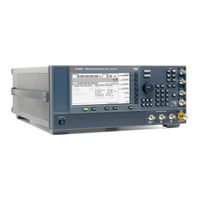
Front Panel26
-
Contents
33-
Standby LED33
-
Symbol Sync33
-
Data Clock33
-
Data34
-
Q Input34
-
I Input34
-
-
Rear Panel
40 -
-
-
Contents
112 -
-
-
Using the ALC159
-
-
-
Contents
202 -
-
Overview228
-
-
-
Real Time MSGPS250
-
Real Time GPS257
-
-
-
Troubleshooting
328 -
Contents
330 -
Sweep Problems
335 -
Error Messages
341
Advertisement
Keysight E8663D User Manual (312 pages)
PSG Signal Generators
Brand: Keysight
|
Category: Portable Generator
|
Size: 3 MB
Table of Contents
-
Options21
-
Swept Signal22
-
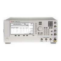
Front Panel24
-
Display25
-
Softkeys25
-
Knob25
-
Amplitude25
-
Frequency25
-
Save25
-
Recall25
-
Trigger26
-
Menus26
-
Help26
-
Ext 1 Input26
-
Ext 2 Input27
-
Lf Output27
-
Mod On/Off27
-
Alc Input27
-
RF On/Off27
-
Rf Output27
-
Sync out28
-
Video out28
-
Incr Set28
-
Arrow Keys28
-
Hold28
-
Return28
-
Local29
-
Preset29
-
Line29
-
Standby LED29
-
Symbol Sync29
-
Data Clock29
-
Data30
-
Q Input30
-
I Input30
-
Annunciators32
-
Text Area34
-
Rear Panel35
-
Event 139
-
Event 239
-
Digital Bus40
-
Q out41
-
I out41
-
I-Bar out41
-
Q-Bar out42
-
Gpib43
-
Mhz EFC43
-
Mhz in44
-
Lan44
-
Mhz out45
-
Sweep out45
-
Trigger out45
-
Trigger in45
-
Rf out47
-
Ext 147
-
Ext 247
-
Alc Input48
-
Data Clock48
-
I in48
-
Symbol Sync48
-
Q in49
-
Data49
-
Lf out49
-
(E8257D))50
-
Source124
-
Using the ALC141
-
To Activate FM165
-
To Activate FM166
-
Overview171
-
Overview193
-
Real Time MSGPS213
-
Scenario Files215
-
Real Time GPS220
-
Overview231
-
Overview241
-
Clock Timing249
-
Data Types262
-
Troubleshooting290
-
Sweep Problems296
-
Error Messages299
Keysight E8663D Service Manual (344 pages)
X-Series
Table of Contents
-
-
-
Assemblies131
-
Hardware163
-
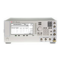
Front Panel View164
-
-
Miscellaneous187
-
Front Panel198
-
A1 Keyboard201
-
A2 Display204
-
A3 Power Switch209
-
-
Tools Required230
-
-
A18Bt1232
-
A19 Power Supply234
-
-
A22 Line Module240
-
-
Tools Required320
-
Advertisement

Keysight E8663D Installation Manual (38 pages)
PSG Signal Generators
Brand: Keysight
|
Category: Portable Generator
|
Size: 0 MB
Table of Contents
-
Environment10
-
Ventilation10
-
Screen Saver12