Pxie vector signal generator 1 mhz to 3 ghz or 6 ghz (45 pages)
Summary of Contents for Keysight 81150A
Page 1
Test Equipment Depot - 800.517.8431 - 99 Washington Street Melrose, MA 02176 - TestEquipmentDepot.com
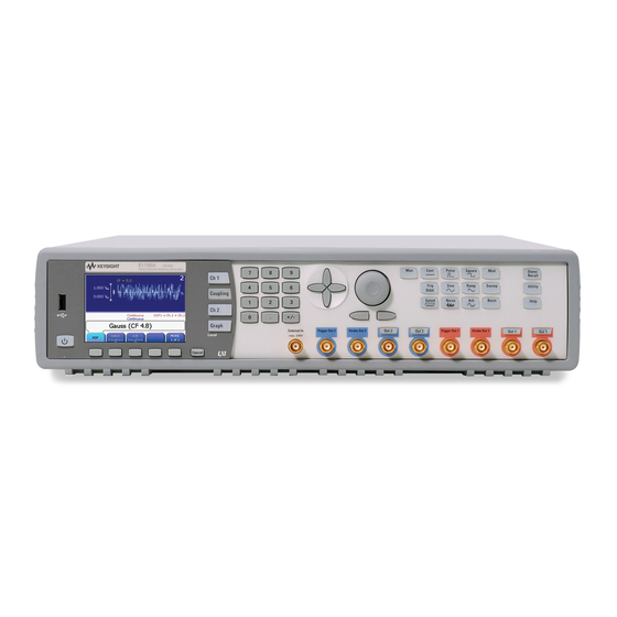
 Keysight 81150A and 81160A Pulse Function Arbitrary Noise Generator User’s Guide...
Page 2
Keysight Pulse Function Arbitrary Noise Generator 81150A and 81160A User’s Guide...
Page 3
Should Keysight and the user have a separate written Edition agreement with warranty terms covering the Edition 2.0, August 2014...
Page 4
Keysight Technologies assumes no liability This instrument is intended for indoor use in for the customer's failure to comply with an installation category II, pollution degree 2 these requirements.
Page 5
General Recycling Mark for plastic parts used in Indicates warning or caution. If you see this Notice for European Community: This product the product. symbol on a product, you must refer to the complies with the relevant European legal manuals for specific Warning or Caution Directives: EMC Directive 89/336/EEC and Low information to avoid personal injury or damage to Voltage Directive 73/23/EEC.
2.3.2 Graph Mode........................ 26 The Front-Panel Number Entry ..................... 27 The Rear Panel ........................28 Preparing the 81150A / 81160A for Use................30 Using the Built-in Help System..................... 31 Selecting the Mode of Operation ..................32 Selecting Trigger Mode and Source ..................33 2.10...
Page 7
2.31.1 GPIB Configuration ....................82 2.31.2 USB Configuration ....................83 2.31.3 LAN Configuration ....................84 2.32 Resetting the 81150A / 81160A ................... 89 Features and Functions ........................90 Trigger Mode .......................... 92 3.1.1 Arming Source ......................94 3.1.2 Arming Slope ......................96 3.1.3 Internal Trigger Period/Frequency ................
Page 9
3.12.2 Start Frequency and Stop Frequency ..............228 3.12.3 Center Frequency and Frequency Span ............... 229 3.12.4 Idle Frequency ......................231 3.12.5 Sweep Type ......................232 3.12.6 Sweep Time......................234 3.12.7 Marker Frequency ....................235 81150A and 81160A User’s Guide...
Page 12
Appendix ............................. 653 Coupled Parameters when channel coupling is on ............653 Pulse Parameter Definitions ....................656 Keysight 81150A / 81160A in comparison with other Keysight instruments ....663 A.3.1 Keysight 81110A/81104A/81101A instrument family......... 663 A.3.2 Keysight 33220A ..................... 665 Preparing a USB Flash Drive using Windows Vista ............
Introduction Introduction Keysight The Keysight Technologies 81150A and 81160A is a Pulse Pattern and Technologies’ Function Arbitrary Noise Generator with built-in arbitrary waveform and 81150A / 81160A pulse capabilities Pulse Function Its combination of bench-top and system features makes this Pulse Function...
Page 14
Purpose of this The purpose of this manual is to enable you to install, initialize, and start the Manual 81150A / 81160A and to understand the front-panel menu features of the 81150A / 81160A. Who should read This manual is intended for testers and Engineers who will be using the this Manual 81150A / 81160A to test other devices.
Page 15
Introduction Topic What information does it contain? Remote Programming Reference Contains reference information to help you program the 81150A / 81160A over the remote interface. Error Messages Describes the error reporting model that is used by the 81150A / 81160A.
Page 16
Appendix References The Getting Started Guide along with this manual forms a part of the 81150A and 81160A product documentation suite.
Front-Panel Menu Operation Front-Panel Menu Operation Introduction This section introduces the front-panel menu and describes the menu features of the 81150A / 81160A Pulse Pattern and Function Arbitrary Noise Generator. 81150A and 81160A User’s Guide...
Page 18
Menu Mode Graph Mode The Front-Panel Number Entry The Rear Panel Preparing the 81150A / 81160A for Use Using the Built-in Help System Selecting the Mode of Operation Selecting Trigger Mode Selecting the Waveform ...
Introduction The instrument is mainly operated from the front panel, when used for benchtop testing. This section explains the Keys, Functions, Inputs/Outputs and Controls, seen on the Front Panel of the 81150A / 81160A. Channel 1 Selection Navigation Rotary Knob...
Page 20
Appendix Power Switch The front panel switch is used to switch on and off the instrument. When the front panel switch is off, the instrument is in standby mode. The instrument is disconnected from the AC line power only by disconnecting the power cord.
Page 21
But the functionality of exiting out of a screen is limited to a few screens, like selecting an Arbitrary waveform. The 81150A / 81160A consists of two channels and operates in two different modes of operation: Coupling off: The two channels operate entirely independent. Frequency generation for both channels is based on same clock reference.
Page 22
(TTL and ECL) or enter test-specific values. Trigger Out is available as a physical BNC connector at the 81150A. For the 81160A, a ‘Logical Trigger Signal’ is generated for channel 1 and channel 2 internally and is routed to the physical BNC connector Sync Out A and/or Sync Out B using a configurable switch matrix.
Page 23
The Utility key enables you to enable/disable DC mode, change the Output Setup, and also contains information about the I/O Interfaces and the system settings of the 81150A / 81160A. The Help key provides access to the instrument’s integrated help or in warning or error state, access to Warning/Error Report screen.
Appendix Help is Available Introduction Whenever you are in doubt or the instrument signals warnings or errors, press the Help key. Pressing the Help key opens the ‘Main Help Page’. This main help page is the table of contents of the integrated help system which lists all the help topics.
This section explains the Menu and the Graph mode as seen on the Front Panel of the 81150A / 81160A. 2.3.1 Menu Mode Introduction This section explains the Menu as seen on the Front Panel of the 81150A / 81160A. Channel Information Channel 1 Information (Channel addition)
Appendix 2.3.2 Graph Mode Introduction To enter the Graph mode, press the key. To exit, press the key again. Not all screens have a graphical representation. The trigger mode screen will always be in textual mode, even if graph ...
0 to 1 border. The left arrow key can be used to delete the digit left to the input cursor when entering values with the numeric keypad. 81150A and 81160A User’s Guide...
A USB Host Connector is used to connect external USB storage device for storing instrument settings or software updates. Rear panel of the 81150A USB Interface Connector (Host type for external mass memory) USB Interface Connector (device type for remote programming)
Page 29
Channel 1 External Modulation Input Terminal Channel 2 External Modulation Input Terminal USB Interface Connector (Host type for external mass memory) USB Interface Connector (device type for remote programming) LAN Interface Connector GPIB Interface Connector Power 81150A and 81160A User’s Guide...
The instrument runs a short power-on self test, which takes about 45-50 Cord and turn on seconds. The 81150A / 81160A powers up in the sine wave function at 1 the 81150A / MHz with an amplitude of 1 Vpp (into a 50 termination) or the power-down 81160A setting.
Whenever a limit is exceeded or any other invalid configuration is found, the information for 81150A / 81160A will display a message. For example, if you enter a value displayed that exceeds the frequency limit for the selected function, a message will be messages displayed.
These are further explained below: Coupling between There are two output channels available for the Keysight 81150A / 81160A. Ch1 & Ch2 The 2 channel version operates in two different modes of operation: Coupling off: The two channels operate entirely independent. Frequency generation for both channels is based on the same clock reference.
The source of a trigger event can be Internal, External, or Manual. The default is External. The following trigger modes are explained below: Continuous External Triggered External Gated Internal Triggered Manual The following table explains the functionality of the 81150A / 81160A. 81150A and 81160A User’s Guide...
Page 34
Appendix Trigger Mode Continuous Function Pulse Square Sine Ramp Noise Arming Source Not Applicable Advanced Mode None Burst Sweep Modulation Trigger Mode Triggered Function Pulse Square Sine Ramp Noise Arming Source MAN Key External-In Internal Advanced Mode None Burst Sweep Trigger Mode Gated Function...
Page 35
External Triggered Triggered generates exactly one ‘signal’ when the trigger condition is met In the external trigger mode, the 81150A / 81160A will accept a hardware trigger applied to the front-panel External In connector. The 81150A / 81160A initiates one sweep or outputs one burst each time External In receives a pulse with the specified edge.
Page 36
Appendix Manual In the manual trigger mode, you can manually trigger the 81150A / 81160A by pressing the front panel key. The 81150A / 81160A initiates one waveform cycle, sweep or outputs one burst for each time you press or release the key.
Front-Panel Menu Operation 2.10 Selecting the Waveform Introduction The 81150A / 81160A can output six standard waveforms including: Pulse Sine Square Ramp Noise Arbitrary You can also select one of the seven built-in arbitrary waveforms or create your own custom waveforms.
Page 38
Appendix Pattern Patterns are defined by the following parameters: Characteristics Internal or external pattern source PRBS patterns and user defined patterns NRZ formatting and Arbitrary Bit Waveform Pattern Mode - On/Off Patterns are also characterized by 2, 3 or 4 different levels per bit ...
Page 39
Load Impedance 81150A: Arbitrary waveforms can have up to 512k samples. The local waveform editor allows to create and edit waveforms with up to 16k samples. 81160A: Arbitrary waveforms can have up to 256k samples (1 channel) / 128k samples (2 channels).
Refer to Chapter 3, Features and Functions to understand how to select any Modulation of these modulations. The 81150A / 81160A will allow only one modulation mode to be enabled at a time. For example, you cannot enable AM and FM at the same time.
Burst Introduction You can configure the 81150A / 81160A to output a waveform with a specified number of pulses/waveform cycles, called a burst. You can output the burst at a rate determined by the internal rate generator or the signal level on the Front Panel External In connector.
The 81150A / 81160A will not allow the sweep mode to be enabled at the same time when burst or any modulation mode is enabled. When you enable sweep, the burst or modulation mode is turned off.
Frequency is already selected, will toggle to Period. softkey The current selection is highlighted as shown in the image below. Enter the Using the numeric keypad, enter the desired value, say 1.2 magnitude of the desired frequency 81150A and 81160A User’s Guide...
Page 44
More softkey to view more units available for the current selection. When you select the units, the 81150A / 81160A outputs a waveform with the displayed frequency (if the output is enabled). You can also enter the desired value using the knob and cursor keys.
This will offer the level representations and units that can be chosen for the output levels. Choose the appropriate option from the given choices. Press More to go to the units screen. Choose from the given units, by pressing that unit itself. 81150A and 81160A User’s Guide...
Page 46
Select the desired Select and press the softkey that corresponds to the desired units. When units you select the units, the 81150A / 81160A outputs a waveform with the displayed amplitude (if the output is enabled). For this example, press mVrms...
This brings you to another menu layer where you can choose between Vpp/Vdc, Vrms/Vdc, dBm/Vdc that will be used when Ampl/Offs is selected. The same softkey menu provides easy application of TTL and ECL level settings. 81150A and 81160A User’s Guide...
Appendix 2.14 Selecting Delay Introduction The time between the start of a period until the start of the waveform is called the delay. The start of a period is defined when the delay is set to 0ns. It can be measured between the Trigger Out and Out Connector. Delay Format Delay has the following format: Abs.
Page 49
Defines the time between the start of a period till the start of the waveform in degrees (1/360 of the period). Selecting any of the delay formats will take you back to the main screen. 81150A and 81160A User’s Guide...
Appendix 2.15 Selecting DC Volts Introduction You can select the "DC Volts" feature from the “Utility” menu, and then set a constant dc voltage as an "Offset" value. As an example, let us set "DC Volts" = -1.5 Vdc. To select DC Volts Steps: Press and then press the DC Mode softkey.
When you change functions, the same offset is used if the present value is valid for the new function. Enter the Using the numeric keypad, enter the value “-1.5” (as shown in the image magnitude of the below). desired offset 81150A and 81160A User’s Guide...
Page 52
Select and press the softkey that corresponds to the desired units. You can units choose from mVdc or Vdc. When you select the units, the 81150A / 81160A outputs the waveform with the displayed offset (if the output is enabled).
This means the duty cycle can get as low as (100% * Wmin/period) and as high as (100% * (1 –Wmin/period)) 81150A: Where Wmin is either 4.1ns or 10ns depending on the selected amplifier (See section Amplifier Type Selection). 81160A: Where Wmin is 1.5ns.
Appendix 2.18 Setting the High-Level and Low-Level Values Introduction You can specify a signal by setting its amplitude and dc offset values. Another way to set the limits of a signal is to specify its high-level (maximum) and low-level (minimum) values. This is typically convenient for digital applications.
Front-Panel Menu Operation 2.19 Configuring a Pulse Waveform Introduction You can configure the 81150A / 81160A to output a pulse waveform with variable pulse width and edge time. The following steps show you how to configure a 500 ms pulse waveform with a pulse width of 10 ms and edge times of 50 ns.
Page 56
Appendix Set the pulse width Press the Width softkey and then set the pulse width to 10 ms. The pulse width represents the start of leading edge to start of trailing edge. Set the edge time Press the Lead Edge and Trail Edge softkeys and then set the edge time for for both edges both the rising and falling edges to 50 ns.
Press the key to select the Pulse function. Setup” key Press the softkey shown in the image below. Pattern Setup This will show the Pattern Setup screen as shown in the following image. 81150A and 81160A User’s Guide...
Page 58
Appendix Press the Select Pattern softkey to select from the available built-in Pattern Mode PRBS patterns or user defined patterns. Use the Rotary Knob or up/down Arrow keys to select. ...
For e.g., if you select Period, then the value of Period will be highlighted in the graph. To exit the Graph Mode, press again. key also serves as a Local key to restore front-panel control after remote interface operations. 81150A and 81160A User’s Guide...
Choose the desired waveform and press select. Confirm your choice by pressing Yes. The 81150A / 81160A has a graphical browser to select the waveform to be used. This waveform can either be a predefined one, or a user defined one (from VOLATILE memory or a stored waveform from NON-VOLATILE memory).
Page 61
Front-Panel Menu Operation For information on creating a custom arbitrary waveform, refer to Creating and Storing an Arbitrary Waveform. 81150A and 81160A User’s Guide...
The load impedance setting is simply provided as a convenience to ensure that the displayed voltage matches the expected load. The Keysight 81160A has a fixed series output impedance of 50 ohms to the front-panel output connector. Press any Press any of the waveform screens, i.e.
Page 63
For Amplifier Type, choose from max Amplitude or max Bandwidth. Type and Range For Amplifier Range, choose from Hold, Auto or Auto Once. Refer to the Amplifier Type Selection section for more information. The Amplifier Type selection is available for the 81150A, only. 81150A and 81160A User’s Guide...
Appendix 2.24 Outputting a Modulated Waveform Introduction A modulated waveform consists of a carrier and a modulating waveform. In AM (amplitude modulation), the amplitude of the carrier is varied by the amplitude of the modulating waveform. For this example, you will output an AM waveform with 80% modulation depth.
Page 65
Press More and then press the AM Shape softkey to select the shape of the modulating modulating waveform. For this example, select a sine wave. waveform shape At this point, the 81150A / 81160A outputs an AM waveform with the specified modulation parameters (if the output is enabled). 81150A and 81160A User’s Guide...
Page 66
Appendix View the waveform Press to view the waveform parameters. To turn off the Graph Mode, press again.
2.25 Outputting an FSK Waveform Introduction You can configure the 81150A / 81160A to “shift” its output frequency between two preset values using FSK modulation. The rate at which the output shifts between the two frequencies (called the “carrier frequency”...
Page 68
Press the FSK Rate softkey and then set the value to 100 Hz using the rate numeric keypad or the knob and arrow keys. At this point, the 81150A / 81160A outputs an FSK waveform (if the output is enabled).
Page 69
Front-Panel Menu Operation View the waveform Press to view the waveform parameters. To turn off the Graph Mode, press again. 81150A and 81160A User’s Guide...
2.26 Outputting a PWM Waveform Introduction You can configure the 81150A / 81160A to output a pulse width modulated (PWM) waveform. The Keysight 81150A / 81160A provides PWM for pulse carrier waveforms, and PWM is the only type of modulation supported for pulse waveforms.
Page 71
Press the PWM Shape softkey to select the shape of the modulating modulating waveform. For this example, select a sine wave. waveform shape At this point, the 81150A / 81160A outputs a PWM waveform with the specified modulation parameters (if the output is enabled). View the waveform Press to view the waveform and parameters.
Appendix 2.27 Outputting a Frequency Sweep Introduction In the frequency sweep mode, the 81150A / 81160A “steps” from the start to the at a which you specify. You can frequency stop frequency sweep rate sweep up or down in frequency, and with either linear or logarithmic spacing.
Page 73
Press the Stop Frequency softkey and then set the value to 5 kHz using the frequency numeric keypad or the knob and cursor keys. At this point, the 81150A / 81160A outputs a continuous sweep from 50 Hz to 5 kHz (if the output is enabled). 81150A and 81160A User’s Guide...
Page 74
key, but only if triggered mode is active. The 81150A / 81160A can also have gated sweeps. In this case it will start a new sweep as long as the gate is active. If the gate is getting inactive while a sweep is generated, this sweep will be finished.
2.28 Outputting a Burst Waveform Introduction You can configure the 81150A / 81160A to output a waveform with a specified number of cycles, called a burst. You can output the burst at a rate determined by the internal rate generator or the signal level on the Front Panel External In.
Page 76
Appendix Start Phase Defines the start phase of the waveform that is bursted. The start phase is only available for sinewave, and arb waveforms. Noise and DC do not have a period and thus no phase information. Square, ramp and pulse is generated in a way that does not allow the use of a start phase.
Page 77
You can also use an external gate signal to either turn the burst signal “on” or “off” based on the external signal applied to the Front panel External In connector. For more information, see Burst Mode. 81150A and 81160A User’s Guide...
Internal or “automatic” triggering is enabled with the default settings of the Internal or 81150A / 81160A. In this mode, the 81150A / 81160A outputs continuously “automatic when the sweep or burst mode is selected.
A fifth storage location automatically holds the power-down configuration of the instrument. When power is restored, the instrument can automatically return to its state before power-down. Select the desired Press and then select the Store State softkey. storage location 81150A and 81160A User’s Guide...
Page 80
Appendix Select a custom If desired, you can assign a custom name to each of the four locations. name for the The name can contain up to 12 characters. The first character must selected location be a letter but the remaining characters can be letters, numbers, or the underscore character (“_”), and “.”.
Page 81
When power is turned off, the instrument automatically stores its power- down state. You can configure the instrument to automatically recall the power-down state when power is restored. 81150A and 81160A User’s Guide...
This section gives information on configuring the 81150A / 81160A for remote interface communication. For information on the SCPI commands available to program the 81150A / 81160A over the remote interface, refer to chapter 4. The Keysight 81150A / 81160A supports remote interface communication using a choice of three interfaces: GPIB, USB, and LAN, explained below.
2.31.2 USB Configuration Introduction The USB interface requires no front panel configuration parameters. Just connect your Keysight 81150A / 81160A to your PC using a standard USB cable and the interface will self configure. 81150A and 81160A User’s Guide...
Appendix 2.31.3 LAN Configuration Introduction There are several parameters that you may need to set to establish network communication using the LAN interface. Primarily, you will need to establish an IP address. You may need to contact your network administrator for help in establishing communication with the LAN interface.
Page 85
Front-Panel Menu Operation Establish an “IP To use the Keysight 81150A / 81160A on the network, you must first Setup” establish an IP setup, including an IP address, and possibly a subnet mask and gateway address. Press the IP Setup softkey. By default, DHCP/Auto-IP (Dynamic Host Configuration Protocol) is set to On.
Page 86
Appendix Set the “Subnet The subnet mask is required if your network has been divided into subnets. Mask” Ask your network administrator whether a subnet mask is needed, and for the correct mask. Press the Subnet Mask softkey and enter the subnet mask in the IP address format (using the keypad).
Page 87
position. Set the “Domain The Domain Name cannot be changed. But, the name that was detected by Name” the Operating System is displayed for information. 81150A and 81160A User’s Guide...
Page 88
Appendix Set the “DNS Press the DNS Server softkey and enter the address of the DNS server Server” address (there are two DNS Server addresses) in the IP address format (using the keypad). Set the “WINS Press the WINS Server softkey and enter the address of the WINS server Server”...
Front-Panel Menu Operation 2.32 Resetting the 81150A / 81160A Introduction To reset the instrument to its factory default state, press and then select the Set to Defaults softkey. Press YES to confirm the operation. The Set to Defaults functionality will program the instrument’s default setting.
This section makes it easy to look up all the details about a particular feature of the 81150A / 81160A. Whether you are operating the 81150A / 81160A from the front panel or over the remote interface, this chapter will be useful.
Page 91
Operation,” starting on page 13, you may want to read it now. Chapter 4, “Remote Programming Reference,” starting on page 289, lists the syntax for the SCPI commands available to program the 81150A / 81160A. Conventions used Throughout this manual, the following conventions are used for SCPI...
Trigger Mode Introduction The Keysight 81150A / 81160A allows you to control the signal generation in several ways. One of the most important ways is selecting a trigger mode. Triggering means start of the signal generation and it does not take place until all ARM conditions are met.
Page 93
Pressing the illuminated key on the Front Panel will show the Trigger Mode screen. Remote Interface To select continuous mode: Operation :ARM:SOURce {IMMediate} To select triggered mode: :ARM:SOURce {INTernal2|EXTernal|MANual} :ARM:SOURce {EDGE} To select gated mode: :ARM:SOURce {EXTernal|MANual} :ARM:SENSe {LEVel} 81150A and 81160A User’s Guide...
External In This input allows to define the decision in a 10 V for 81150A (5 V for 81160A) voltage window. The input signal is referenced to chassis ground. 81150A: The input impedance may be set to either 50 or 10 k.
Page 95
Trigger Operation Mode screen. Choose the appropriate Source as shown below. The screenshots above are taken from the 81150A. The 81160A offers External In additional functionality described in chapter 3.3.1 “ Parameters ”.
Appendix Remote Interface :ARM:SOURce {INTernal2|EXTernal|MANual} Operation Selecting the source of the arming signal is related to setting the triggering mode of the instrument. See section 3.1 for more details. 3.1.2 Arming Slope Introduction Trigger events can be generated on the rising edge, the falling edge, or on both edges of the selected arming signal.
Features and Functions The screenshots above are taken from the 81150A. The 81160A offers External In additional functionality described in chapter 3.3.1 “ Parameters ”. Remote Interface :ARM:SLOPe {POSitive|NEGative|EITher} Operation 3.1.3 Internal Trigger Period/Frequency Introduction The internal trigger period/frequency defines the time between two trigger events if the trigger source is set to Internal.
Page 98
Appendix Trigger Frequency 81150A: 1 Hz to 120 MHz (default 100 kHz) Characteristics Trigger Frequency 81160A: 1 Hz to 330 MHz (default 100 kHz) Trigger Period 81150A: 8.3333 ns to 1000000s (default 10 s) Trigger Period 81160A: 3.03 ns to 1000000s (default 10 s) ...
Features and Functions Output Configuration Introduction This section contains information to help you configure the 81150A / 81160A for outputting waveforms. You may never have to change some of the parameters discussed here, but they are provided to give you the flexibility you might need.
Page 100
Appendix Table Description The table below shows which output functions are allowed with modulation, sweep, and burst. Each “•” indicates a valid combination. If you change to a function that is not allowed with modulation, sweep, or burst, then the modulation or mode is turned off. Sine Square Ramp Pulse Pattern Noise DC Arb AM, FM, PM...
81160A: 330 MHz Burst Limitations The maximum frequency when doing burst is 120 MHz for the 81150A (330 MHz for the 81160A). This frequency limit applies additionally to the functions max frequency limit. Practically, this is only relevant for sine waves, since all other waveforms have a maximum frequency of 120 MHz for the 81150A (330 MHz for the 81160A).
Page 102
Trigger Limitations When using triggered mode, the maximum frequency of the waveform is limited to 120 MHz for the 81150A (330 MHz for the 81160A). The trigger events may not occur faster than the duration of the waveform being triggered. This limits the maximum trigger rate to 120 MHz for the...
Page 103
Features and Functions Duty Cycle For square and pulse waveforms, the 81150A / 81160A may not be able to Limitations use the full range of duty cycle values at higher frequencies as shown below: Duty cycle is limited by minimum width specification.
But, if the new termination does result in voltages that can be done with the 81150A / 81160A, then the values that are displayed on the front panel will be applied at the output.
Page 105
Converter). For example, the built-in “Sinc” waveform does not use the full range of values between ±1 and therefore its maximum amplitude is limited to 6.087 Vpp (into 50 ohms) for 81150A. While changing amplitude, you may notice a momentary disruption in ...
Page 106
Appendix Remote Interface The following function is used to configure the output amplitude remotely: Operation :VOLTage[1|2] {<NR3>|MINimum|MAXimum} Or, you can set the amplitude by specifying a high level and low level using the following commands. :VOLTage[1|2]:HIGH {<volts>|MINimum|MAXimum} :VOLTage[1|2]:LOW {<volts>|MINimum|MAXimum} You can also use the APPLy command to select the function, frequency, amplitude, and offset with a single command.
Limits due to The offset limits are determined by the current output termination setting. Output Termination The 81150A / 81160A keeps the configured voltages. However, if this is not possible, it shows an error message. Arbitrary Waveform For arbitrary waveforms, the maximum offset and amplitude will be limited if...
Page 108
Appendix To set the dc offset, press the Offset softkey for the selected Front-Panel function. Then use the knob or numeric keypad to enter the desired Operation offset. To set the offset using a high level and low level, press the Offset softkey again to toggle to the High and Low softkeys.
Power On state is set to “default”). Characteristics The 81150A / 81160A uses the current units selection for both front panel and remote interface operations. For example, if you select “VRMS” from the remote interface, the units are displayed as “V ”...
Applies to output amplitude and offset voltage only a selectable series output impedance of 50 or 5 to the front-panel connector. The Keysight 81160A has a fix series output impedance of Output 50 . If the actual load impedance is different than the value specified, the displayed amplitude and offset levels will be incorrect.
3.2.7 Output Source Impedance Introduction 81150A: An impedance of 50 , 5 is selectable. 81160A: The output source impedance is 50 fix. Source Impedance The source impedance is stored in volatile memory; it is set to 50 (default...
Appendix 3.2.8 Voltage Autoranging Introduction Autoranging is enabled by default and the 81150A / 81160A automatically selects the optimal settings for the output amplifier and attenuators. With autoranging disabled, the 81150A / 81160A uses the current amplifier and attenuator settings.
Features and Functions 3.2.9 Amplifier Type Selection The Amplifier Type Selection applies to the 81150A only. The 81160A has one type of amplifier. See the data sheet for the output amplifier specifications of the 81160A. Introduction There are two different amplifiers available for each channel inside the 81150A.
Appendix 3.2.10 Digital Channel Addition Introduction If the instrument is equipped with 2 output modules, channel 2 can be added to channel 1 internally. The maximum output voltage remains unchanged. In this case, the second channel outputs the unchanged waveform of channel two.
Voltage Limits, press the Voltage Limits softkey again. High Volt Limit is used to set the maximum allowed voltage. Low Volt Limit is used to set the minimum allowed voltage. Remote Interface :VOLTage[1|2]:LIMit:STATe {OFF|ON} Operation :VOLTage[1|2]:LIMit{<voltage>}MINimum|MAXimum} :VOLTage[1|2]LIMit:LOW {<voltage>|MINimum|MAXimum} 81150A and 81160A User’s Guide...
(100% * Wmin/period) and Characteristics as high as (100% * (1–Wmin/period)) 81150A: Where Wmin is either 4.1ns or 10ns depending on the selected amplifier (See section Amplifier Type Selection). 81160A: Where Wmin is 1.5 ns.
Page 117
Then use the knob or numeric keypad to enter the desired duty cycle. Remote Interface The following function is used to configure the duty cycle remotely: Operation :FUNCtion[1|2]:SQUare:DCYCl{<percentage>| MINimum|MAXimum} The APPLy command automatically sets the duty cycle to 50%. 81150A and 81160A User’s Guide...
Appendix 3.2.13 Symmetry (Ramp Waves) Introduction Applies to ramp waves only. Symmetry represents the amount of time per cycle that the ramp wave is rising (assuming that the waveform is not inverted). The symmetry is stored in volatile memory; the symmetry is set to Symmetry ...
:OUTput[1|2] {0|1|OFF|ON} :OUTPut[1|2]:COMPlement {0|1|OFF|ON} The APPLy command overrides the current setting and automatically enables the connector. Output In case of an overload condition, both outputs of the channel (Normal and Inverted) will be turned off. 81150A and 81160A User’s Guide...
3.2.15 Parameter Coupling Introduction The 2 channels of the Keysight 81150A / 81160A can work as 2 completely independent instruments that use some shared resources like External-In, Man key and Clock Reference. For applications that require some locking of the two channels, the 81150A / 81160A provides two means of synchronization.
Page 121
2. Front Panel This can be found on the Pulse, Sine, Square, Ramp, and Arb screens. Operation The Frequency Multiplier and Frequency Divider will be enabled only when the Frequency Coupling State is enabled. 81150A and 81160A User’s Guide...
Page 122
Appendix Remote Interface The following function is used to configure Frequency Coupling remotely: Operation :TRACk:FREQuency {ON|OFF} The following functions are used to configure the frequency of channel 1 and channel 2. :TRACk:FREQuency:DIVider {<divider>} :TRACk:FREQuency {<multiplier>} The allowed range for divider and multiplier are 1-255. But are limited by the currently active frequency limits of channel 2.
Page 123
Features and Functions Channel Coupling Introduction The Keysight 81150A / 81160A allows to use the two channels completely independent, or in a frequency and phase locked mode. Characteristics In the Channel Coupling mode, the frequency and phase of both the channels are locked.
Appendix 3.2.16 Polarity Introduction In the normal mode (default), the waveform goes positive during the first part of the cycle. In the inverted mode, the waveform goes negative during the first part of the cycle. As shown in the examples below, the waveform is inverted relative to Waveform Polarity ...
3.2.17 Strobe Output Introduction 81150A: One strobe output for each channel is provided on the front-panel. The strobe output signal provides different meanings depending on the mode of operation. 81160A: The ‘Logical Strobe Signal’ is an internally generated signal that can be routed to the BNC connector of Sync Out A or Sync Out B.
If noise is selected the Trigger Output is constant Low if the trigger mode is continuous or gated. If the trigger mode is triggered, then Trigger-Out will generate a 4.16 ns for 81150A (1.5 ns for 81160A) pulse when the noise generation is being reset to the start of the noise sequence.
3.2.19 Sync Output Introduction The Sync Outputs exist on the 81160A, only. The 81150A has one Trigger Output per channel and one Strobe Outputs per channel. For the one channel instrument as well as the two channel instrument of 81160A two high speed Sync Out A and Sync Out B outputs are provided at the front panel.
Page 128
Appendix Front Panel Press one of the trigger mode keys ( , or ) to display Operation the Trigger Mode Screen. The settings above indicate that ‘Logical Trigger Signal 1’ is routed to Sync A. ‘Logical Strobe Signal 1’ is routed to Sync B. Sync A and Sync B output levels are set to TTL.
This section contains information on the following parameters: External In Parameters Threshold Voltage Input Impedance Modulation In Parameters Input Voltage Range Input Impedance FSK Threshold Voltage Reference Clock 81150A and 81160A User’s Guide...
81150A and 81160A: Input Impedance 81160A only: Hysteresis 81160A only: Frequency Front Panel Press one of the trigger mode keys ( , or ) to display Operation the Trigger Mode Screen. Trigger Mode Screen of the 81150A...
Page 131
The External In Threshold Voltage defines the threshold voltage that is used to detect signals at the ExternalIn Connector. The Threshold can be set to any voltage in the range of 10 V to +10 V for the 81150A (5 V to +5 V for the 81160A).
Page 132
Operation Input Impedance Introduction 81150A: The Input Impedance of the External In connector can be set to 50 or 10 k. 81160A: The Input Impedance of the External In connector can be set to 50 or 1 k.
Page 133
Features and Functions Remote Interface :ARM[:SEQuence][:STARt][:LAYer]:HYSTeresis [LOW | HIGH] Operation Frequency Introduction 81160A only: The frequency applied to External In is measured. Remote Interface :ARM[:SEQuence][:STARt][:LAYer]:EFREquency?/qonly/ Operation [ NR3] 81150A and 81160A User’s Guide...
These are explained below. Input Voltage Range Introduction 81150A only: When selecting external modulation source, the Input Voltage Range defines the full scale of the modulation signal. It can be selected between 2.5V and 5V. 81160A: The input voltage range is 2.5V fix.
Page 135
Features and Functions Press the MOD-IN softkey to go to the Modulation In screen. Front Panel Press the Input Range softkey. Operation Remote Interface :AM[1|2]:EXTernal:RANGe {<volts>|MINimum|MAXimum} Operation :FM[1|2]:EXTernal:RANGe {<volts>|MINimum|MAXimum} :PM[1|2]:EXTernal:RANGe {<volts>|MINimum|MAXimum} :PWM[1|2]:EXTernal:RANGe {<volts>|MINimum|MAXimum} :FSK[1|2]:EXTernal:RANGe {<volts>|MINimum|MAXimum} 81150A and 81160A User’s Guide...
Page 136
Appendix Input Impedance Introduction When selecting external modulation source, impedance of the Modulation- In connector can be selected between 50 and 10 k. Front Panel Press the MOD-IN softkey to go to the Modulation In screen. Operation Press the Impedance softkey. Remote Interface :FSKey[1|2]:EXTernal:IMPedance{<ohms>|MINimum| MAXimum}...
Page 137
If the signal levels are more than the Modulation-In Threshold, then the output signal will have the Hop Frequency The allowed range is 5V for the 81150A (2.5V for the 81160A); and is limited by Modulation-In Input Range.
The PLL state indicates whether the internal PLL is locked or unlocked. This is also reflected in the Questionable Data Register. Refer to the Remote Interface Reference for more information. 81150A and 81160A User’s Guide...
Page 140
Appendix Front Panel Press , and then Reference Clock softkey. Operation Remote Interface :ROSCillator:SOURce {INTernal|EXTernal} Operation :ROSCillator:SOURce:AUTO {ON|OFF}...
Pulse Width refers to the start of leading edge to start of trailing edge. In this format, the pulse-width is independent of changes in pulse period and delay. Pulse Width Rise Time Fall Time Period 81150A and 81160A User’s Guide...
81150A: Pulse period limits: 8.33 ns to 1000000 s. Pulse Period 81160A: Pulse period limits: 3.03 ns to 1000000 s. Characteristics Pulse frequency limits: 1 Hz to 120 MHz for 81150A. 1 Hz to 330 MHz for 81160A The default value is 1 s/1MHz. ...
Pulse Width Wmin Pulse Width Period Wmin 81150A: Where Wmin is either 4.1ns or 10ns depending on the selected amplifier (See section Amplifier Type Selection). 81160A: Where Wmin is 1.5 ns. Front-Panel After selecting the pulse function, press the Width/Duty Cycle/Trailing Operation Delay softkey.
Page 144
Appendix Trail Delay The trailing delay is the absolute delay from the start of the pulse period to the start of the trailing edge. In this format the trailing edge remains fixed relative to the start of the pulse period if you adjust the pulse-delay (leading- edge delay) or the pulse period.
Characteristics default edge time is 2.5 ns. 81150A: The minimum edge time is limited to 7.5 ns. If the amplifier type is set to “max. Amplitude.” 81160A: Edge time: 1.0 ns to 1000 s. The default edge time is 1.0 ns.
Page 146
Appendix Remote Interface The following function is used to configure the Leading Edge remotely: Operation :PULSe:TRANsition[1|2]{<seconds percentage>|MINimum|MAXimum} :FUNCtion[1|2]:PULSe:TRANsition{<secondso percentage>|MINimum|MAXimum} The following function is used to configure the Trailing Edge remotely: :PULSe:TRANsition[1|2]:TRAiling{<seconds percentage>|MINimum|MAXimum} :PULSe:TRANsition[1|2]:TRAiling:AUTO{OFF|ON|ONCE} :FUNCtion[1|2]:PULSe:TRANsition:TRAiling:AUTO {OFF|ON|ONCE} It is used to set the automatic coupling of the pulse-trailing-edge transition time to the leading-edge transition time.
Page 147
amplitude, offset, high level, low level, load impedance, output impedance and polarity) with the exception of width and trailing edge are valid for pattern mode also. This is further explained in the following sections. 81150A and 81160A User’s Guide...
for serial protocols that require electrical idle signaling in the data streams. 81150A: Up to 16 Mbit long memory 2- level based patterns. Up to 8 Msymbols long memory based 3- and 4-level patterns. 81160A, 1 channel: Up to 4 Mbit long memory 2- level based patterns.
This parameter enables the pattern mode. The Pattern Mode can be set to On/Off. Front Panel After selecting the Pattern Setup softkey, press the Pattern Mode softkey to Operation enable or disable pattern mode. Remote Interface :DIGital[1|2]{ON|OFF} Operation 81150A and 81160A User’s Guide...
Additionally it is possible to provide an externally generated data stream at MOD-IN for re-shaping by the 81150A / 81160A. To do this, select the external pattern source. For details on external pattern, refer to the External Patterns section.
Page 151
Features and Functions Remote Interface :DIGital[1|2]:SOURce {INTernal|EXTernal} Operation 81150A and 81160A User’s Guide...
Introduction External patterns are provided at the MOD-IN connector of the rear panel. In external or ‘pass-through’ pattern mode, the 81150A / 81160A can be used to re-time and re-shape and externally provide data stream according to the configured data rate, output levels, number of levels and formatting settings like any internal generated pattern.
Page 153
When selecting external pattern source, the Input Voltage Range defines the full scale of the pattern signal. It can be selected between ±2.5V and ±5V for the 81150A (is fix ±2.5V for the 81160A). On the pattern mode screen press the Ext. Input Setup softkey.
Page 154
Appendix Sample Mode Introduction The sample mode defines how the 81150A / 81160A is sampling the externally provided data stream. In fixed sampling mode there is a fix relation between the sampling time and the rising edge of the TRIGGER-OUT signal.
Page 155
(e.g. 1/10 of a unit interval), but you have a reduced delay and you can still adjust amplitude/offset of the re-generated signal. Transition time adjustment or arbitrary bitshapes are limited to one period of the 81150A / 81160A frequency (e.g. 1/10 of a unit interval). 81150A and 81160A User’s Guide...
Page 156
Appendix On the pattern mode screen press the Ext. Input Setup softkey. Front Panel Press the Sample Mode softkey. Operation Remote Interface :DIGital[1|2]:SOURce:EXTernal:SAMPling {AUTO|FIXed} Operation Number of Levels Introduction Defines the number of levels that have to be detected in the provided external pattern signal.
Page 157
Press the Number of Levels softkey. Operation Enter the number of levels using the numerical keypad, or turn the rotary knob to select the desired number of levels. Remote Interface :DIGital[1|2]:SOURce:EXTernal:THReshold {<volts>|MINimum|MAXimum} Operation 81150A and 81160A User’s Guide...
Page 158
Appendix Upper Threshold Voltage Introduction The upper threshold voltage defines the voltage level at which a sample is considered being a logical ‘1’. If the voltage at MOD-IN is above the upper threshold voltage, then the external provided bit is considered being ‘1’. If the voltage is above the lower threshold, but less than or equal to the upper threshold, then the bit is considered being an idle symbol (will result in the programmed offset voltage at the output).The upper threshold is only used...
The preview usually doesn’t show the complete pattern. Front Panel After selecting the Pattern Setup softkey, press the Select Pattern softkey. Operation Use the Rotary Knob or Arrow Keys to select the desired Pattern. 81150A and 81160A User’s Guide...
Page 160
Appendix Select Highlighted Click Yes to confirm and No to reject the selected pattern. Pattern Remote Interface :DIGital[1|2]:SELect <name> Operation :MMEMory:LOAD:PATTern VOLATILE, “<filename>”...
EDIT softkey to reach the Pattern Editor screen as shown below: Configure the new Configure the new pattern by providing all the information shown in the pattern above screen. When done press the EDIT softkey to open the new created pattern in the pattern editor. 81150A and 81160A User’s Guide...
Page 162
Appendix Remote Interface :DIG:NLEV 2 Operation :DIG:FORM PACKED,1 :DIG:DATA #2161001101001001001 Number of Bits Defines the initial number of bits in the pattern. For most efficient and easiest editing, the desired pattern length should be chosen on this screen. In case of setting up too less or too many bits here, this can be changed by inserting or removing bits in the process of editing the pattern later on.
Page 163
Pattern Edit On the Pattern Edit screen, Bits can be inserted and deleted, the pattern can be edited, the loop offset can be modified and the pattern can be stored to the non-volatile memory. 81150A and 81160A User’s Guide...
Page 164
Press the STORE in NON-VOL softkey to leave the editor, apply the edited pattern to the hardware and store the pattern in non-volatile memory. The 81150A / 81160A provides 4 non-volatile memory locations for patterns. Additionally it is possible to store the pattern to a external USB memory device.
Page 165
After pressing the STORE in NON-VOL softkey in the pattern editor, the Operation pattern browser opens. This allows storing the pattern to one of the 4 built- in memory locations for patterns, or to an external USB memory device. 81150A and 81160A User’s Guide...
Page 166
The pattern is now stored in non-volatile memory and is currently being output from the 81150A / 81160A. You can select the storage location by scrolling up and down in the list using the up/down arrow keys or the knob.
Page 167
After selecting the Edit Pattern softkey, press the Delete Stored softkey to Operation delete a pattern. Press DELETE to delete a stored user defined pattern as shown in the following image. Remote Interface Delete a pattern from the internal non-volatile storage locations Operation :DIGital[1|2]:DELete <name> 81150A and 81160A User’s Guide...
Appendix 3.5.6 Bitshape Selection Introduction If the bit shape parameter on the pattern setup screen is set to Arbitrary, it is possible to select a predefined or use a userdefined waveform that defines the shape of a bit. The screens operate similar to the standard Arb mode.
Page 169
Select a bit shape that is stored in internal non-volatile memory Operation :DIGital[1|2]:TRANsition:SELect <name> Load a bit shape from external USB memory to VOLATILE memory :MMEMory:LOAD:TRANsition VOLATILE, “<filename>” Define the bit shape programmatically :DIGital[1|2]:TRANsition <value>,<value>,… :DIGital[1|2]:TRANsition:DAC <blockdata> 81150A and 81160A User’s Guide...
Appendix 3.5.7 Creating, Editing and Storing a Bitshape Introduction This section gives an example which shows you how to create, edit and store an arbitrary bit waveform from the front panel. Front Panel After selecting the Pattern Setup softkey, press MORE, and then press the Operation Edit Bit Waveform softkey.
Page 171
“step-like” waveform. For this example, turn on linear interpolation. Remote Interface Operation :DIG:TRAN:INT {ON|OFF|0|1} For bitshapes, interpolation can be enabled from front panel as well as through SCPI. 81150A and 81160A User’s Guide...
Page 172
Appendix Auto Update On: Changes of the waveform will be applied immediately to the output. The editor is slower. Off: The waveform will be applied to output when editing is finished. The editor is faster due to missing hardware update. EDIT Start the point-by- Press the EDIT softkey to accept the initial waveform settings and begin...
Page 173
If Point #1 is removed, then Point #2 will be placed to address 0. Remove Point is not possible if the waveform has 2 points, since this is the minimum waveform length. 81150A and 81160A User’s Guide...
Page 175
END Edit does apply the waveform to the hardware and exits the editor. In bit waveform in this case, the changes are only done on the volatile memory of the memory waveform. STORE in NON-VOL does open the waveform browser to store the waveform in non-volatile memory. 81150A and 81160A User’s Guide...
Appendix 3.5.8 Triggered and Gated Patterns Introduction In contrast to other functions like pulse, sinewave or square, triggering or gating patterns does not always refer to exactly one unit interval, or one burst of the selected function. In pattern mode, it is possible to select whether a trigger event will cause the generation of the complete pattern, or just a single bit.
Page 177
Features and Functions Remote Interface :DIGital[1|2]:TRIGger {BIT|BLOCk} Operation 81150A and 81160A User’s Guide...
Appendix Noise Introduction Noise is specified by the following parameters: Amplitude/Offset or High/Low Level Probability Density Function (PDF) Characteristics The probability of seeing a specific output level can be defined by the PDF. Gaussian distribution with a crest factor of 3.1 ...
Page 179
Noise. This brings you to the following Operation screen. Front Panel Press the PDF softkey and choose from the available noise characteristic Operation options, as shown below. Remote Interface :FUNCtion[1|2]:NOISe:PDFunction{PDF1|PDF2|PDF3| PDF4|USER} Operation 81150A and 81160A User’s Guide...
When you enable AM, the previous modulation mode is turned off. The 81150A / 81160A will not allow AM to be enabled at the same time that sweep or burst is enabled. When you enable AM, the sweep or burst mode is turned off.
3.7.1 Selecting AM Modulation Front-Panel The 81150A / 81160A will allow only one modulation mode to be enabled at Operation a time. For example, you cannot enable AM and FM at the same time. When you enable AM, the previous modulation mode is turned off.
Appendix 3.7.2 Carrier Waveform Shape Introduction AM carrier shape: Sine, Square, Ramp, or Arbitrary waveform. . You use pulse, noise, or dc as the carrier The default is Sine cannot waveform. Press any of the front-panel function keys except . For Front-Panel Operation arbitrary waveforms, press...
Then use the knob or numeric keypad to enter the desired frequency. Remote Interface :FREQuency[1|2] {<frequency>|MINimum|MAXimum} Operation You can also use the APPLy command to select the function, frequency, amplitude, and offset with a single command. 81150A and 81160A User’s Guide...
3.7.4 Modulating Waveform Shape Introduction The 81150A / 81160A will accept modulation from an internal or external modulation source. In case of internal modulation, the modulation signal can be the ‘other channel’ (2 channel instrument only) or the internal modulation source of the modulated channel.
3.7.5 Modulating Waveform Frequency Introduction The 81150A / 81160A will accept modulation from an internal or external modulation source. In case of internal modulation, the modulation signal can be the ‘other channel’ (2 channel instrument only) or the internal modulation source of the modulated channel.
At 100% depth, the output amplitude equals the selected value. Modulation depth: 0% to 120%. The default is 100%. Even at greater than 100% depth, the 81150A / 81160A will not exceed the specified amplifier’s output voltage window or specified output amplitude.
Page 187
Features and Functions 81150A and 81160A User’s Guide...
Appendix 3.7.7 DSSC (Double Sideband Suppressed Carrier Mode) Introduction If DSSC is enabled, then the carrier will no longer be present in the modulated signal. Characteristics DSSC is only available if modulation is enabled, modulation type is AM. AM can be performed with or without carrier suppression. DSSC = OFF Modulation Depth...
Page 189
Features and Functions 81150A and 81160A User’s Guide...
3.7.8 Modulating Source Introduction The 81150A / 81160A will accept modulation from an internal or external modulation source. In case of internal modulation, the modulation signal can be the ‘other channel’ (2 channel instrument only) or the internal modulation source of the modulated channel.
When you enable FM, the previous modulation mode is turned off. The 81150A / 81160A will not allow FM to be enabled at the same time that sweep or burst is enabled. When you enable FM, the sweep or burst mode is turned off.
Appendix 3.8.1 Selecting FM Modulation Front-Panel You must enable FM before setting up any of the other modulation Operation parameters. Press and then select “FM” using the Modulation Type softkey. The FM waveform is output using the present settings for the carrier frequency, modulating frequency, output amplitude, and offset voltage.
Select softkey to select the active waveform. Waveform Remote Interface :FUNCtion[1|2]{SINusoid|SQUare|RAMP|USER} Operation You can also use the APPLy command to select the function, frequency, amplitude, and offset with a single command. 81150A and 81160A User’s Guide...
If you attempt to set the deviation to a value Characteristics greater than the carrier frequency (with FM enabled), the 81150A / 81160A will automatically adjust the deviation to the maximum value allowed with the present carrier frequency.
3.8.4 Modulating Waveform Shape Introduction The 81150A / 81160A will accept modulation from an internal or external modulation source. In case of internal modulation, the modulation signal can be the ‘other channel’ (2 channel instrument only) or the internal modulation source of the modulated channel.
3.8.5 Modulating Waveform Frequency Introduction The 81150A / 81160A will accept modulation from an internal or external modulation source. In case of internal modulation, the modulation signal can be the ‘other channel’ (2 channel instrument only) or the internal modulation source of the modulated channel.
100 kHz. If you attempt to set the deviation to a value that is not valid, the 81150A / 81160A will limit it to the maximum value allowed with the present carrier frequency.
3.8.7 Modulating Source Introduction The 81150A / 81160A will accept modulation from an internal or external modulation source. In case of internal modulation, the modulation signal can be the ‘other channel’ (2 channel instrument only) or the internal modulation source of the modulated channel.
PM is very similar to FM, but in PM the phase of the modulated waveform is varied by the instantaneous voltage of the modulating waveform. For more information on the fundamentals of Phase Modulation, refer to the Tutorial chapter. 81150A and 81160A User’s Guide...
PM, the previous modulation mode is turned off. The 81150A / 81160A will not allow PM to be enabled at the same time that sweep or burst is enabled. When you enable PM, the sweep or burst mode is turned off.
More key. Press the Select Waveform softkey to select the active waveform. Remote Interface :FUNCtion[1|2]{SINusoid|SQUare|RAMP|USER} Operation You can also use the APPLy command to select the function, frequency, amplitude, and offset with a single command. 81150A and 81160A User’s Guide...
Pattern 81150A: 120 MHz 81160A-330: 330 MHz 81160A-660: 660 MHz 81150A and 81160A: 10 MHz for external patterns Front-Panel To set the carrier frequency, press the Frequency softkey for the selected Operation function. Then use the knob or numeric keypad to enter the desired frequency.
3.9.4 Modulating Waveform Shape Introduction The 81150A / 81160A will accept modulation from an internal or external modulation source. In case of internal modulation, the modulation signal can be the ‘other channel’ (2 channel instrument only) or the internal modulation source of the modulated channel.
3.9.5 Modulating Waveform Frequency Introduction The 81150A / 81160A will accept modulation from an internal or external modulation source. In case of internal modulation, the modulation signal can be the ‘other channel’ (2 channel instrument only) or the internal modulation source of the modulated channel.
180 degrees. Front Panel After enabling PM, press the Phase Deviation softkey. Then use the knob or Operation numeric keypad to enter the desired deviation. Remote Interface :PM[1|2]:DEViation{<deviation in degrees>|MINimum|MAXimum} Operation 81150A and 81160A User’s Guide...
3.9.7 Modulating Source Introduction The 81150A / 81160A will accept modulation from an internal or external modulation source. In case of internal modulation, the modulation signal can be the ‘other channel’ (2 channel instrument only) or the internal modulation source of the modulated channel.
3.10 Frequency-Shift Keying (FSK) Modulation Introduction You can configure the 81150A / 81160A to “shift” its output frequency between two preset values using FSK modulation. The rate at which the output shifts between the two frequencies (called the “carrier frequency”...
When you enable FSK, the previous modulation mode is turned off. The 81150A / 81160A will not allow FSK to be enabled at the same time that sweep or burst is enabled. When you enable FSK, the sweep or burst mode is turned off.
More Press the softkey to select the active waveform. Select Waveform Remote Interface :FUNCtion[1|2] {SINusoid|SQUare|RAMP|USER} Operation You can also use the APPLy command to select the function, frequency, amplitude, and offset with a single command. 81150A and 81160A User’s Guide...
The maximum carrier frequency depends on the function selected as shown below. The default is 1 MHz for all functions. Function Minimum Frequency Maximum Frequency Sine 81150A: 240 MHz 81160A: 500 MHz Square 81150A: 120 MHz 81160A: 330 MHz...
To set the “hop” frequency, do the following: Operation Press and then press the Modulation Type softkey to select FSK. Press the Hop Frequency softkey. Then use the knob or numeric keypad to enter the desired frequency. 81150A and 81160A User’s Guide...
FSK source. FSK rate (internal source): FSK “Hop” 81150A: 1 mHz to 10 MHz. Frequency 81160A: 1 mHz to 50 MHz. Characteristics The default is 10 Hz. The FSK rate is ignored when the external FSK source or other ...
DAC value 0 will output the hop frequency. Front-Panel After enabling FSK, press the FSK Source softkey and select from Internal, Operation Channel, or External. Remote Interface :FSKey[1|2]:SOURce{INTernal[1]|INTernal2| EXTernal} Operation 81150A and 81160A User’s Guide...
(expressed in time units, like the period) or a duty cycle (expressed as a percentage of the period). The 81150A / 81160A will accept modulation from an internal or external modulation source. In case of internal modulation, the modulation signal can be the ‘other channel’...
The 81150A / 81160A only allows PWM to be selected for a pulse waveform, and PWM is the only modulation type supported for pulse. The 81150A / 81160A will not allow PWM to be enabled at the same time that sweep or burst is enabled.
Appendix 3.11.2 Pulse Waveform Introduction Pulse is the only waveform shape supported for PWM. Front-Panel Press to select pulse. Operation Remote Interface :FUNCtion {PULSe} Operation You can also use the APPLy command to select the function, frequency, amplitude, and offset with a single command.
Pulse Period Introduction 81150A: The range for the pulse period is 8.33 ns to 1000000s. The default is 1 s. Pulse frequency limits: 1 Hz to 120 MHz. 81160A: The range for the pulse period is 3.03 ns to 1000000s. The default is 1 s.
3.11.4 Modulating Waveform Shape Introduction The 81150A / 81160A will accept modulation from an internal or external modulation source. In case of internal modulation, the modulation signal can be the ‘other channel’ (2 channel instrument only) or the internal modulation source of the modulated channel.
3.11.5 Modulating Waveform Frequency Introduction The 81150A / 81160A will accept modulation from an internal or external modulation source. In case of internal modulation, the modulation signal can be the ‘other channel’ (2 channel instrument only) or the internal modulation source of the modulated channel.
Width Deviation ≤ Pulse Width Wmin Width Deviation ≤ Period - Pulse Width Wmin 81150A: Where Wmin is either 4.1 ns or 10 ns depending on the selected amplifier (See section Amplifier Type Selection). 81160A: Where Wmin is 1.5 ns.
Duty Cycle Deviation Duty Cycle 100 x Wmin ÷ Period Duty Cycle Deviation 100 Duty Cycle 100 x Wmin ÷ Period 81150A: Where Wmin is either 4.1 ns or 10 ns depending on the selected amplifier (See section Amplifier Type Selection).
Page 222
Appendix Front-Panel After enabling PWM, press the Dty Cyc Deviation softkey. Then use the Operation knob or numeric keypad to enter the desired deviation. Go to the Pulse Screen, press the Width softkey and switch to Duty Cycle. Press the Modulation Key. Instead of “Width Deviation” the softkey ...
Page 223
If you select Width for the pulse waveform and enable , the Width Deviation softkey is available. On the other hand, if you select Duty Cycle for the pulse waveform and enable , the Dty Cyc Deviation softkey is available. 81150A and 81160A User’s Guide...
3.11.8 Modulating Source Introduction The 81150A / 81160A will accept modulation from an internal or external modulation source. In case of internal modulation, the modulation signal can be the ‘other channel’ (2 channel instrument only) or the internal modulation source of the modulated channel.
3.12 Frequency Sweep Introduction In the frequency sweep mode, the 81150A / 81160A “steps” from the start frequency to the stop frequency at a sweep rate which you specify. You can sweep up or down in frequency, and with either linear or logarithmic spacing.
Selecting a Sweep Introduction The 81150A / 81160A will not allow the sweep mode to be enabled at the same time that burst or any modulation mode is enabled. When you enable sweep, the burst or modulation mode is turned off.
The 81150A / 81160A begins at the start frequency, sweeps to the stop frequency, and then resets back to the start frequency Start and Stop frequencies: Characteristics ...
(see the previous page) and are included to give you added flexibility. 81150A: Center frequency: 1 µHz to 240 MHz. The default is 550 Hz. Characteristics 81160A: Center frequency: 1 µHz to 500 MHz. The default is 550 Hz.
Page 230
Appendix Front-Panel After enabling , press the Start Frequency or Stop Frequency softkey Operation again to toggle to the Center Freq or Freq Span softkey. Then use the knob or numeric keypad to enter the desired values. Remote Interface :FREQuency[1|2]:CENTer{<frequency>|MINimum| MAXimum} Operation :FREQuency[1|2]:SPAN {<frequency>|MINimum|MAXimum}...
Press the Idle Frequency softkey or use the navigation keys to select Idle frequency. softkey again or use the rotary knob to select from Press the Idle Frequency Start Frequency, Stop Frequency, or 0 Hz (DC). Remote Interface :SWEep[1|2]:IDLE {SFRequency|EFRequency|DC} Operation 81150A and 81160A User’s Guide...
You can sweep with either linear or logarithmic spacing. The default is Linear. For a linear sweep, the 81150A / 81160A varies the output frequency in a linear fashion during the sweep. sweep, the 81150A / 81160A varies the output frequency in For a logarithmic a logarithmic fashion.
Page 233
Features and Functions 81150A and 81160A User’s Guide...
The sweep time specifies the number of seconds required to sweep from the start frequency to the stop frequency. The number of discrete frequency points in the sweep is automatically calculated by the 81150A / 81160A and is based on the sweep time you select.
If you attempt to set the marker frequency to a frequency not in this range, the 81150A / 81160A will automatically set the marker frequency equal to the start frequency or stop frequency (whichever is closer).
Triggered/Gated Sweep Introduction In the triggered mode, the 81150A / 81160A outputs a single sweep when a trigger signal is received. After one sweep from the start frequency to the stop frequency, the 81150A / 81160A waits for the next trigger while outputting the idle frequency.
Page 237
Features and Functions Remote Interface Use the following command to specify whether the 81150A / 81160A Operation triggers on the rising or falling edge of the signal on the External In connector. :ARM:SOURce{IMMediate|INTernal[1]|INTernal[2]| EXTernal|MANual} :ARM:FREQuency[1|2] {<frequency>|MAXimum|MINimum} :ARM:SENSe[1|2]{EDGE|LEVel} :ARM:PERiod[1|2] {<seconds>|MAXimum|MINimum} :ARM:SLOPe {POSitive|NEGative|EITHer} For more information, refer to the Triggering Commands section.
3.13 Burst Mode Introduction You can configure the 81150A / 81160A to output a waveform with a specified number of cycles, called a burst. The 81150A / 81160A can produce a burst using sine, square, ramp, pulse, or arbitrary waveforms (noise and dc is not allowed).
Selecting a Burst Introduction The 81150A / 81160A will not allow the burst to be enabled at the same time that sweep or any modulation mode is enabled. When you enable burst, the sweep or modulation mode is turned off.
Appendix 3.13.2 Continuous Burst Mode Introduction The following figure shows typical timings for trigger mode Continuous enabled. Burst A burst of waveform cycles is repeated continuously. Characteristics You can select the number of cycles per burst in the range of 2 to ...
You can select the number of cycles per burst in the range of 2 to 1,000, 000. Trigger Out marks each cycle. Strobe Out rises at the start of the first cycle in a burst and falls at the start of the last cycle. 81150A and 81160A User’s Guide...
Appendix 3.13.4 Gated Burst Mode Introduction The following figures show typical timings for trigger mode Gated Burst enabled. Characteristics Bursts of waveform cycles are enabled by (Gated by) an active level at the selected arming source: Man key on front panel, gated while pressed or released or both. ...
Burst Count ≤ Internal trigger period x Output frequency Front Panel To set the burst count, press the #Cycles softkey and then use the knob or Operation numeric keypad to enter the count. Remote Interface :BURSt[1|2]:NCYCles {<#cycles>|MINimum|MAXimum} Operation :TRIGger[1|2]:COUNt {<#cycles>|MINimum|MAXimum} 81150A and 81160A User’s Guide...
(radians are not available). If you set the starting phase in radians from the remote interface and then return to front-panel operation, you will see that the 81150A / 81160A converts the phase to degrees. For sine, and arb waveforms, 0 degrees is the point at which the ...
81150A or 81160A. The Keysight BenckLink Wabeform Builder software allows you to create arbitrary waveforms using a graphical user interface on your PC, and then download them into the Keysight 81150A / 81160A. You can also capture waveforms from your Keysight oscilloscope and import them into BenchLink.
Appendix 3.14.1 Creating and Storing an Arbitrary Waveform Introduction This section gives an example which shows you how to create and store an arbitrary waveform from the front panel. To download an arbitrary waveform from the remote interface, see “Arbitrary Waveform Commands”. For this example, you will create and store the ramp waveform shown below using four waveform points.
Page 247
Features and Functions Configure the new Configure the new waveform by providing all the information shown in the waveform following screen. 81150A and 81160A User’s Guide...
Page 248
Appendix Set the initial You can create an arbitrary waveform with up to 16384 (16K) points. number of The waveform editor initially builds a waveform with two points and waveform points automatically connects the last point of the waveform to the voltage level of the first point to create a continuous waveform.
Page 249
Press the X softkey to set the address for the current point (this softkey is not available for Point #1). Press the Y softkey to set the DAC value for the current point. For this example, set X to 3279 and Y to 8191. 81150A and 81160A User’s Guide...
Page 250
Appendix Define the Using the X and Y softkeys, define the remaining waveform points using the remaining values shown in the table below. waveform points The X value of the last point that can be defined in the waveform must be less than 16384 (16K).
Page 251
END Edit does apply the waveform to the hardware and exits the editor. In waveform in this case, the changes are only done on the volatile memory of the memory waveform. STORE in NON-VOL does open the waveform browser to store the waveform in non-volatile memory. 81150A and 81160A User’s Guide...
Page 252
STORE softkey to store the waveform. The waveform is now stored in non-volatile memory and is currently being output from the 81150A / 81160A. The name that you used to store the waveform should now appear in the list of stored waveforms (under the...
There are four built-in storage locations for arbitrary waveforms. Introduction You can store arbitrary waveforms on a USB mass memory device. You can load arbitrary waveforms from the USB mass memory device into the volatile memory. 81150A and 81160A User’s Guide...
Page 254
Only waveforms of upto 16K points can be created/edited using the Front Panel interface. Larger waveforms must be edited using an external application, such as Keysight BenchLink Waveform Builder, and then downloaded into the 81150A / 81160A.
Page 255
SELECT This softkey selects the currently highlighted waveform. STORE This softkey stores the content of the volatile memory to one of the four user-defined waveform storage locations or to the USB memory. 81150A and 81160A User’s Guide...
Appendix 3.14.3 Additional Information on Arbitrary Waveforms Introduction The currently selected waveform is displayed on the Arb screen. In addition to creating a new arbitrary waveform from the front panel, you can also edit any existing user-defined waveforms. You can edit waveforms that were created either from the front panel or from the remote interface.
This section gives information on topics such as instrument state storage, power-down recall, error conditions, self test, and front-panel display control. This information is not directly related to waveform generation but is an important part of operating the 81150A / 81160A. 81150A and 81160A User’s Guide...
3.15.1 Instrument State Storage Introduction The 81150A / 81160A has five storage locations in non-volatile memory to store instrument states. The locations are numbered 0 through 4. Storage location “0” holds the instruments default state. It is not possible to store an instrument state to location “0”.
Page 259
Recall and Delete keys are both disabled if nothing is stored ( and thus nothing to Recall/Delete exists). To configure the 81150A / 81160A to recall the factory default state at power-on, press and then select the Power-ON State softkey. To configure the 81150A / 81160A to recall the power-down state when power is restored, press the Power-ON State softkey and select Last Setting.
Page 260
From the remote interface, you can only recall a stored state using a number (0 through 4). MEMory:STATe:NAME {1|2|3|4}, name MEM:STATE:NAME 1,TEST_WFORM_1 To configure the 81150A / 81160A to automatically recall the power-down state when power is restored, send the following command: MEMory:STATe:RECall:AUTO ON...
Features and Functions 3.15.2 Export/Import State Introduction The 81150A / 81160A can store instrument states on a USB memory device, usually this is a USB stick, but could also be a hard drive. Front Panel Press the key and then the More softkey. You will then see two Operation softkeys labeled Export State and Import State.
Page 262
Appendix Press the Export State/Import State softkey to store to recall from Press USB memory devices. Export/Import Choose from DELETE/STORE/RECALL and press the corresponding softkey softkey. softkey to define/set file name. This name will Press the File Name ...
returned is the first error that was stored. Errors are cleared as you read them. The 81150A / 81160A beeps once each time an error is generated (unless you have disabled the beeper). If more than 30 errors have occurred, the last error stored in the ...
Page 264
Appendix Remote Interface SYSTem:ERRor? Operation Reads one error from the error queue Errors have the following format (the error string may contain up to 255 characters). -113,"Undefined header" :SYSTem:WARNing:BUFFer? Returns the number of active warnings. :SYSTem:WARNing:STRing? Returns all active warning messages.
3.15.4 Beeper Control Introduction Normally, the 81150A / 81160A will emit a tone when an error is generated from the front-panel or over the remote interface. You may want to disable the front-panel beeper for certain applications. The beeper state is stored in non-volatile memory and does not Characteristics ...
Appendix 3.15.5 Display Brightness Introduction To optimize the readability of the front-panel display, you can adjust the brightness setting. This feature is available from the front panel only Characteristics Display brightness: 0 to 7. The default is 0. The brightness setting is stored in non-volatile memory and does not change when power has been off or after a remote interface reset.
Display Control Introduction For security reasons, or to speed up the rate at which the 81150A / 81160A can execute commands from the remote interface, you may want to turn off the front-panel display. From the remote interface, you can also display a 12- character message on the front panel.
Page 268
Appendix Remote Interface The following command turns off the front-panel display: Operation DISP OFF The following command displays a message on the front panel and turns on the display if currently disabled: 'Test in Progress…’ DISP:TEXT To clear the message displayed on the front panel (without changing the display state), send the following command: DISP:TEXT:CLEAR...
Displays the time which is set on the instrument. Front Panel Press and then System softkey. Press MORE and then the Time Operation softkey Remote Interface :SYSTem:TIME {<hours>,<minutes>,<seconds>} Operation :SYSTem:TIME? The time can be modified using the Rotary Knob. 81150A and 81160A User’s Guide...
Appendix 3.15.8 Date Introduction Displays the date which is set on the instrument. Front Panel Press and then System softkey. Press MORE and then the Date Operation softkey The date can be modified using the Rotary Knob. Remote Interface :SYSTem:DATE {<years>,<month>,<day>} Operation :SYSTem:DATE?
Features and Functions 3.15.9 Firmware Revision Query Introduction You can query the 81150A / 81160A to determine which revision of firmware is currently installed. Front-Panel Press and then press System, and then press the Configuration Operation softkey. Remote Interface Use the following command to read the 81150A / 81160A’s firmware...
3.15.10 SCPI Language Version Query Introduction The 81150A / 81160A complies with the rules and conventions of the present version of SCPI (Standard Commands for Programmable Instruments). You can determine the SCPI version with which the instrument is in compliance by sending a query from the remote interface.
/ 81160A and connect it to your PC using a GPIB cable. . There is nothing to configure on your 81150A / USB Interface 81160A. Just connect the 81150A / 81160A to the PC with a USB cable. . By default, DHCP is On, which may enable network LAN Interface ...
Each device on the GPIB (IEEE-488) interface must have a unique address. You can set the 81150A / 81160A’s address to any value between 0 and 30. The address is set to “10” when the 81150A / 81160A is shipped from the factory.
DHCP (Dynamic Host Configuration Protocol) is a protocol for automatically assigning a dynamic IP address to a device on a network. DHCP is typically the easiest way to configure your Keysight 81150A / 81160A for remote communication using the LAN interface. DHCP/Auto-IP is by default.
"nnn.nnn.nnn.nnn" where "nnn" in each case is a byte value from 000 to 255. You can enter an IP address for Keysight 81150A / 81160A. You need not set an IP address if DHCP is in use. Setting up an IP ...
Operation Then select LAN, followed by IP Setup. By default, DHCP is On. Select DHCP Off if necessary. Then select Subnet Mask. There is no SCPI command to set a subnet mask. 81150A and 81160A User’s Guide...
Appendix 3.16.5 Default Gateway (LAN) Introduction A gateway is a network device that provides a connection between networks. The default gateway setting is the IP address of such a device. You need not set a gateway address if DHCP is in use. Setting up a default ...
Front panel Press and then the I/O Interfaces softkey. operation Then select LAN, followed by DNS Setup. Then select Host Name. There is no SCPI command to set a host name. 81150A and 81160A User’s Guide...
I/O Interfaces softkey. Operation Then select LAN, followed by DNS Setup. The Domain name cannot be changed. The 81150A / 81160A simply displays the name of the domain that was determined when the instrument was connected to the LAN.
I/O Interfaces softkey. Operation Then select LAN, followed by DNS Setup. Then select DNS Server 1 or DNS Server 2. There is no SCPI command to set a DNS server address. 81150A and 81160A User’s Guide...
Appendix 3.16.9 WINS Server (LAN) Introduction WINS (Windows Internet Naming Service) is an Internet service that translates Host names to IP addresses. The WNS server address is the IP address of a server that performs this service. Contact your network administrator to find out whether WINS is Setting up a WNS ...
Page 283
I/O Interfaces softkey. Operation Then select LAN, followed by DNS Setup. Then select WINS Server 1 or WINS Server 2. There is no SCPI command to set a WINS server address. 81150A and 81160A User’s Guide...
Appendix 3.16.10 Current Configuration (LAN) Introduction The current configuration is displayed on the LAN screen. Changes to the LAN settings will be applied immediately. It is not required to re-boot after changing the LAN settings.
Page 285
Features and Functions Try the Keysight 81150A / 81160A Web Interface! The Keysight 81150A / 81160A provides a web interface resident in the instrument. You can use this interface over the LAN to view and modify the instrument’s I/O configuration. Also, a remote front panel interface is provided, which allows you to control the instrument over the network.
Appendix 3.17 Software Update Introduction The Software Update screen gives you prompt information about the 81150A / 81160A. The software update package contains two firmware images. Both will be extracted to the USB memory device during the update process. In case of a power-loss during the update, the instrument will load the recovery image from the USB memory device if the regular firmware image is corrupt.
Page 287
Operation Configuration softkey to reach the Software Update screen. Press the Software Update softkey for instructions on how to update the instrument with the latest software. This is shown below in the second screen. 81150A and 81160A User’s Guide...
Appendix 3.18 Installing Licenses Introduction Some of the features of the 81150A / 81160A are enabled by additional software licenses. Installed licenses are being displayed on the system configuration screen. Additional licenses can be installed by entering the license code that is provided by Keysight Technologies when ordering a specific license.
Page 289
Features and Functions 81150A and 81160A User’s Guide...
Appendix 3.19 Diagnostics/Calibration Overview Introduction The 81150A / 81160A provides a self-calibration functionality. The diagnostics screen allows to review the power-on messages, to execute the instruments self-test (standard + extended) and to perform the self- calibration. All cables need to be disconnected before executing the extended self-test or self-calibration.
Page 291
Remove all cables from the instrument before starting the extended selftest. Performing Press the Extended Selftest softkey to reach this screen. Press Yes to start Extended Selftest Extended Selftest and No to exit. Remove all cables from the instrument before starting the extended selftest. 81150A and 81160A User’s Guide...
Page 292
Appendix Performing Press the Calibration softkey to reach this screen. Press Yes to start Calibration calibration and No to exit. Remove all cables from the instrument before starting the calibration. Remote Interface The following functions are used to execute the selftests: Operation *TST? :SYSTem:TEST? {PON|NORM|ALL}...
Features and Functions 3.20 Security Introduction The 81150A / 81160A provides security functionality. Front Panel Press and then press the System softkey. Operation Press the Security softkey. Secure All Pressing this key deletes all user data and shuts down the machine.
The power-on state will be different than that in the table if you have enabled the power-down recall mode. See “Instrument State Storage”. Keysight 81150A / 81160A Factory Default Settings Output Configuration Factory Setting Function Sine wave...
Page 295
Features and Functions Trail Edge (Pulse) 81150A: 2.5 ns 81160A: 1.2 ns Symmetry (Ramp) 100% 81150A and 81160A User’s Guide...
Page 296
Appendix Noise Configuration Factory Setting Gaussian with Crest Factor 3.1 Arb Configuration Factory Setting Waveform Exponential Rise Pattern Configuration Factory Setting Pattern Mode Pattern Source Internal Pattern PRBS 2^7-1 Bit Shape Bit Waveform CAP_2 External Patterns Number of Levels Sample Mode Fixed Lower Threshold Voltage...
Page 297
FSK Hop Frequency 100 Hz FSK Rate 10 Hz PWM Width Deviation 500 ps Modulation State Sweep Factory Setting Start/Stop Frequency 100 Hz/1 kHz Sweep Time 1 Second Sweep Mode/Type Linear Sweep State/Frequency Marker 81150A and 81160A User’s Guide...
Page 298
*Web Server *Enabled *Web Server Password *AGT81150 (81150A only) *Keysight (81160A only) Parameters marked with an asterisk are stored in non-volatile memory. Parameter groups marked with a will be part of the stored instrument state. The content of the...
Local key on the Front Panel. The USB interface requires no front panel configuration parameters. Just connect your Keysight 81150A / 81160A to your PC using a standard USB cable and the interface will self configure. There are several parameters that you may need to set to establish network communication using the LAN interface.
Sufficient to use: sets the leading edge in seconds output 1 :PULS:TRAN The commands to set the timing and level parameters, 81150A / 81160A is a real 2 channel instrument have to be specified for output 1 and output 2. If there is no output specified the command will set the default output 1.
Page 301
# enable the output 1 :OUTP1 ON Selftest of the instrument can be invoked by the common command. *TST? If it is important to know whether the last command is completed then send the common command. *OPC? 81150A and 81160A User’s Guide...
Internal self-calibration *CAL? Clear the Status Structure *CLS <NR1> Standard Event Status Register *ESE[?] Standard Event Status Event Register *ESR? *IDN? Instrument’s Identification *LRN? Complete Instrument Setting *OPC Operation Complete Return 1 *OPC[?] Installed Options *OPT? 81150A and 81160A User’s Guide...
Page 316
Appendix Command Parameter Description *PSC[?] Power On Status 0|1|2|3|4 Recall Instrument Setting *RCL *RST Reset *SAV 1|2|3|4 Save Instrument Setting Service Request Enable Mask *SRE[?] Status Byte *STB? Software Trigger *TRG Start Instrument’s Selftests *TST? Wait until all pending actions are complete *WAI...
Remote Programming Reference 81150A / 81160A SCPI Instrument Command List Format Introduction The following reference sections list the instrument commands in alphabetical order. In addition to a command description, the attributes of each command are described under the following headings. Not all of these attributes are applicable to all commands.
Appendix 81150A / 81160A SCPI Instrument Elements Name Introduction The following table presents some of the most common <suffix names> elements used while referring to some units in the instrument. The following table gives both, the short name and its expanded name for the most commonly used units.
“MINimum”, “MAXimum” or “DEFault” can also be used here. The default offset is 0.0 V for all functions. APPLy Command Syntax (examples) APPL:SIN 5.0e3, 3.0 ,0.0 APPL:NOIS def, 5.0, 2.0 APPL:PULS def, def, def is the same as APPL:PULS APPL:DC def, def, -2.5 81150A and 81160A User’s Guide...
Page 320
Appendix APPLy command The APPLy command performs the following operations: Operations Sets the trigger source to Immediate (equivalent to sending the ARM:SOUR IMM command). Turns off any modulation, sweep, or burst mode currently enabled and places the instrument in the continuous waveform mode. Turns on the Output connector (OUTP ON command) but does not ...
Page 321
The function, frequency, amplitude, and offset are returned as shown in the sample string below (the quotation marks are returned as part of the string). Example :APPL1? Response: "SIN+5.0000000000000E+03,+3.0000000000000E+00,- 2.5000000000000E+00" 81150A and 81160A User’s Guide...
Page 322
Appendix Command :APPL[1|2]:DC Long :APPLy[1|2]:DC Parameters [<frequency|DEFault>[,<amplitude>|DEFault> [,<offset>]]] Parameter Suffix Description Output a dc voltage with the level specified by the offset parameter. You can set the dc voltage to any value between ±5 Vdc into 50 ohms or ±10 Vdc into an open circuit or depending on the selected amplifier type.
Page 323
“DEFault”. If you specify a frequency, it has no effect on the noise output, but the value is remembered when you change to a different function. Example :APPL:NOIS DEF, 5.0, 2.0 81150A and 81160A User’s Guide...
Page 324
Appendix Command :APPL[1|2]:PULS Long :APPLy[1|2]:PULSe Parameters [<frequency>[,<amplitude>[,<offset>]]] Parameter Suffix Description Output a pulse wave with the specified frequency, amplitude, and dc offset. The waveform is output as soon as the command is executed. This command preserves the current pulse width setting (FUNC:PULS:WIDT command) or pulse duty cycle setting (FUNC:PULS:DCYC command), depending on which has been selected to “hold”...
Page 325
Output a ramp wave with the specified frequency, amplitude, and dc offset. This command overrides the current symmetry setting and automatically selects 100%. The waveform is output as soon as the command is executed. Example :APPL:RAMP 4MHz, 3.42, 0.1 81150A and 81160A User’s Guide...
Page 326
Appendix Command :APPL[1|2]:SIN Long :APPLy[1|2]:SINusoid Parameters [<frequency>[,<amplitude>[,<offset>]]] Parameter Suffix Description Output a sine wave with the specified frequency, amplitude, and dc offset. The waveform is output as soon as the command is executed. Example :APPL1:SIN 120MHz, 4.2, 1.7...
Page 327
Output a square wave with the specified frequency, amplitude, and dc offset. This command overrides the current duty cycle setting and automatically selects 50%. The waveform is output as soon as the command is executed. Example :APPL1:SQU 110e6, 2.4, -1.25 81150A and 81160A User’s Guide...
Page 328
Appendix Command :APPL[1|2]:USER Long :APPLy[1|2]:USER Parameters [<frequency>[,<amplitude>[,<offset>]]] Parameter Suffix Description Output the arbitrary waveform currently selected by the FUNC:USER command. The waveform is output using the specified frequency, amplitude, and dc offset. The waveform is output as soon as the command is executed. Example :APPL1:USER 3MHz, 1.2, -0.1...
(A-Z), but the remaining characters can be numbers (0-9) or the underscore character (“ _ ”). Blank spaces are not allowed. If you specify a name with more than 12 characters, a “Program mnemonic too long” error is generated. 81150A and 81160A User’s Guide...
Page 330
Description Download floating-point values from -1.0 to +1.0 into volatile memory. You can download from 1 to Sample points per waveform. 81150A: Sample = 524288 (512 k) 81160A 1 channel: Sample = 262144 (256 k) 81160A 2 channels: Sample...
Page 331
on page 339) instead of a comma separated specification :DATA[1|2]:DAC of the waveform as the binary download is faster than the comma separated one. Example :DATA VOLATILE, 1, .67, .33, 0, -.33, -.67, -1. 81150A and 81160A User’s Guide...
Page 332
Appendix Command :DATA[1|2]:ATTR:AVER? Long :DATA[1|2]:ATTRibute:AVERage? Parameters [<arb name>] Parameter Suffix Description Query the arithmetic average of all data points for the specified arbitrary waveform (-1 average +1). The default arb- name is the arbitrary waveform currently active (selected with FUNC:USER command). If you query a waveform that is not currently stored in memory, a “Specified arb waveform does not exist”...
Page 333
The default arb- name is the arbitrary waveform currently active (selected with FUNC:USER command). If you query a waveform that is not currently stored in memory, a “Specified arb waveform does not exist” error is generated. Example :DATA1:ATTR:CFAC? EXP_RISE Response 1.239349433E+01 81150A and 81160A User’s Guide...
Page 334
Description Query the number of points in the specified arbitrary waveform. Returns a value from 1 to Sample points. 81150A: Sample = 524288 (512 k) 81160A 1 channel: Sample = 262144 (256 k) 81160A 2 channels: Sample = 131072 (128 k) The default arb-name is the arbitrary waveform currently active (selected with FUNC:USER command).
Page 335
±1 and therefore its maximum amplitude is lower (into 50 ohms). If you query a waveform that is not currently stored in memory, a “Specified arb waveform does not exist” error is generated. Example :DATA:ATTR:PTP? EXP_RISE Response 1.0000E+00 81150A and 81160A User’s Guide...
Page 336
Appendix Command :DATA[1|2]:CAT? Long :DATA[1|2]:CATalog? Parameters Parameter Suffix Description List the names of all waveforms currently available for selection. Returns the names of the seven built-in waveforms (non-volatile memory), “VOLATILE” if a waveform is currently downloaded to volatile memory, and all user-defined waveforms downloaded to non-volatile memory.
Page 337
CARDIAC and NEG_RAMP. If you specify one of the built-in waveforms, a “Cannot overwrite a built-in waveform” error is generated. The instrument does not distinguish between upper- and lower-case letters. Therefore, ARB_1 and arb_1 are the same name. All characters are converted to upper case. 81150A and 81160A User’s Guide...
Page 338
Appendix Description If you copy to a waveform name that already exists, the previous waveform is overwritten (and no error will be generated). However, you cannot overwrite any of the seven built-in waveforms. Up to four user-defined waveforms can be stored in non-volatile memory. If memory is full and you try to copy a new waveform to nonvolatile memory, a “Not enough memory”...
Page 339
The maximum amplitude will be limited if the data points do not span the full range of the output DAC. The DATA:DAC command overwrites the previous waveform in volatile memory (and no error will be generated). Use the DATA:COPY command to copy the waveform to non-volatile memory. 81150A and 81160A User’s Guide...
Page 340
Appendix Description Up to 4 user-defined waveforms can be stored in non-volatile memory. Use the DATA:DEL command to delete the waveform in volatile memory or any of the four user-defined waveforms in nonvolatile memory. Use the DATA:CAT? command to list all waveforms currently stored in volatile and non-volatile memory (as well as the seven built-in waveforms).
Page 341
If one of the waveforms is currently being output, a “Not able to delete the currently selected active arb waveform” error is generated. Example :DATA:DEL ARB_1 81150A and 81160A User’s Guide...
Page 342
Appendix Command :DATA[1|2]:DEL:ALL Long :DATA[1|2]:DELete:ALL, Parameters Parameter Suffix Description Delete all user-defined arbitrary waveforms from memory. This command deletes the waveform in volatile memory and all user-defined waveforms in non-volatile memory. The seven built-in waveforms in non-volatile memory are not deleted. The colon before the ALL parameter is required (DATA:DELete:ALL).
Page 343
DATA[1|2] commands which loads the VOLATILE memory of the instrument. For a more detailed description of the data format, refer to :DATA VOLATILE SCPI command or Appendix of this document. Example :DATA:MOD VOLATILE, 0.2, 1.0, -1.0, 0.5, -0.75 81150A and 81160A User’s Guide...
Page 344
Appendix Command :DATA[1|2]:MOD:DAC Long :DATA[1|2]:MODulation:DAC Parameters {VOLATILE,<binary block>|<value>, <value>, <value>, …} Parameter Suffix Description Addresses the internal 16K (16384) modulation memory. It can be used to download an arbitrary waveform into the modulation memory which can be used as modulating waveform for a signal generated by the instrument. It corresponds to the DATA[1|2] …...
Page 345
(A-Z), but the remaining characters can be numbers (0-9) or the underscore character (“ _ ”). Blank spaces are not allowed. If you specify a name with more than 12 characters, a “Program mnemonic too long” error is generated. Example :DATA:MOD:COPY ARB_1,VOLATILE 81150A and 81160A User’s Guide...
Page 346
Appendix Command :DATA[1|2]:NVOL:CAT? Long :DATA[1|2]:NVOLatile:CATalog? Parameters Parameter Suffix Description Lists the names of all user-defined arbitrary waveforms downloaded to non- volatile memory. Returns the names of up to four waveforms. A series of quoted strings separated with commas is returned as shown in the example below.
Page 347
Query the number of free non-volatile memory slots available to store user- defined waveforms. Returns the number of memory slots available to store user-defined waveforms. Returns “0” (memory is full), “1”, “2”, “3”,or “4” Example :DATA2:NVOL:FREE? Response 81150A and 81160A User’s Guide...
Page 348
Appendix Command :DATA[1|2]:NVOL:QUAN? Long :DATA[1|2]:NVOLatile:QUANtity? Parameters Parameter Suffix Description Query the number of total non-volatile memory slots available to store user- defined waveforms. Returns “4”. Example :DATA2:NVOL:QUAN? Response...
Page 349
The instrument represents binary data as signed 16-bit integers, which are sent as two bytes. Therefore, each waveform data point requires 16 bits, which must be transferred as two bytes on the instrument’s interfaces. Example :FORM:BOARD NORM 81150A and 81160A User’s Guide...
Page 350
Appendix Command :FUNC[1|2]:MOD:USER[?] Long :FUNCtion[1|2]:MODulation:USER[?] Parameters {<arb name>|VOLATILE} Parameter Suffix Description Select one of the seven built-in arbitrary waveforms, one of four user- defined waveforms, or the waveform currently downloaded to volatile memory. The :FUNC:USER? query returns either EXP_RISE, EXP_FALL, HAVERSINE, SINC, CARDIAC, VOLATILE, GAUSSIAN, NEG_RAMP or the name of any user-defined waveforms in non-volatile memory.
Page 351
Use the DATA:CAT? command to list the names of the seven built-in waveforms (non-volatile). VOLATILE if a waveform is currently downloaded to volatile memory, and the names of any user-defined waveforms (non-volatile). Example :FUNC1:USER VOLATILE 81150A and 81160A User’s Guide...
Appendix 4.5.3 Burst Commands Introduction A burst is a certain number of cycles generated by the instrument on a single event. The burst of a cycle can be triggered by an internal or external trigger signal. When the gated burst mode is selected, the last ‘Burst’ of cycles will always be completed.
Page 353
Long :BURSt:GATE:POLarity[?] Parameters {NORMal|INVerted} Parameter Suffix Description Selects whether the instrument uses true-high or true-low logic levels on the externally-gated burst. It corresponds with :ARM:SLOP POS|NEG command. Application recommendation: Use :ARM:SLOP Example :BURS:GATE:POL NEG 81150A and 81160A User’s Guide...
Page 354
Appendix Command :BURS[1|2]:INT:PER[?] Long :BURSt[1|2]:INTernal:PERiod[?] Parameters {<NR3>|MINimum|MAXimum} Parameter Suffix Description Set the burst period for internally-triggered bursts. The burst period defines the time from the start on one burst to the start of the next burst. It corresponds with the :ARM:PERiod or :ARM:FREQ command. Example :BURS:INT:PER 10MHZ...
Page 355
Long :BURSt[1|2]:MODE[?] Parameters {TRIGgered|GATed} Parameter Suffix Description Sets trigger on the edge or gate level at the external input. It corresponds width the :ARM:SENS EDGE|LEV command. . Application recommendation: Use :ARM:SENS Example :BURS1:MODE TRIG 81150A and 81160A User’s Guide...
Page 356
Appendix Command :BURS[1|2]:NCYC[?] Long :BURSt[1|2]:NCYCles[?] Parameters {<#cycles>|MINimum|MAXimum} Parameter Suffix Description :TRIGger[1|2]:COUNt and :BURSt:NCYCles set the number of triggered periods to be generated per arm event. :TRIGger:COUNt > 1 is the short form of :BURSt:NCYCles and :BURST:STATe. In other words for example :TRIGger:COUNt 3 set the BURSt:STATe to ON and :BURTs:NCYCles to 3.
Page 357
The burst phase is also used in the gated burst mode. When the gate signal goes false, the current waveform cycle is completed and then the instrument stops. The output will remain at the voltage level corresponding to the starting burst phase. Example :BURS:PHAS 211.2 81150A and 81160A User’s Guide...
Page 358
Appendix Command :BURS[1|2]:STAT[?] Long :BURSt[1|2]:STATe[?] Parameters {ON|OFF} Parameter Suffix Description :TRIGger[1|2]:COUNt and :BURSt[1|2]:NCYCles set the number of triggered periods to be generated per arm event. :TRIGger:COUNt > 1 is the short form of :BURSt:NCYCles and :BURST:STATe. In other words for example :TRIGger:COUNt 3 set the BURSt:STATe to ON and :BURTs:NCYCles to 3.
Page 359
:TRIGger:COUNt > 1 is the short form of :BURSt:NCYCles and :BURST:STATe. In other words for example :TRIGger:COUNt 3 set the BURSt:STATe to ON and :BURTs:NCYCles to 3. Example :TRIG:COUN 17 81150A and 81160A User’s Guide...
Page 360
Appendix Command :UNIT[1|2]:ANGL[?] Long :UNIT[1|2]:ANGLe[?] Parameters {DEGree|RADian} Parameter Suffix Description Select degrees or radians to set the phase offset value (remote interface only). The default is DEG. The :ANGL? query returns “DEG” or “RAD”. From the front panel, the phase offset is always displayed in degrees (radians are not available).
4.5.4 Level Commands Introduction The following SCPI command subsystem specifies all the commands to change amplitude, offset, high-level and low-level of a sigal to be output. The Amplitude can be specified as VPP, VRMS, dBm. 81150A and 81160A User’s Guide...
Page 362
Appendix Level Commands Command :VOLTage[1|2] Long [:SOURCE]:VOLTage[1|2] [:LEVel][:IMMediate][:AMPLitude] Parameters {<NR3>|MINimum|MAXimum} Parameter Suffix VPP, VRMS, DBM, V Description Set the output amplitude. MIN selects the smallest amplitude MAX selects the largest amplitude for the selected function. The :VOLT[1|2]:UNIT command specifies the unit the amplitude will be interpreted (VPP, VRMS or DBM).
Page 363
Command :VOLT[1|2]:HIGH[?] Long [:SOURCE]:VOLTage[1|2][:LEVel][:IMMediate]:HIGH[?] Parameters {<NR3>|MINimum|MAXimum} Parameter Suffix Description Set the high voltage level. MIN selects the most negative voltage level for the selected function and MAX selects the largest voltage level. Example :VOLT2:HIGH 1.33 81150A and 81160A User’s Guide...
Page 364
Appendix Command :VOLT[1|2]:LOW[?] Long [:SOURCE]:VOLTage[1|2] [:LEVel][:IMMediate]:LOW[?] Parameters {<NR3>|MINimum|MAXimum} Parameter Suffix Description Set the low voltage level. MIN selects the most negative voltage level for the selected function and MAX selects the largest voltage level. Example :VOLT1:LOW -1.2...
Page 365
Parameters {VPP|VRMS|DBM} Parameter Suffix Description Selects the unit for output amplitude (does not affect offset voltage or high/low levels. The default is Vpp. The :VOLT:UNIT? Query returns “VPP”, “VRMS” or “DBM”. Example :VOLT2:UNIT VPP 81150A and 81160A User’s Guide...
Page 366
Appendix Command :VOLT[1|2]:LIM[?] Long [:SOURCE]:VOLTage[1|2]:LIMit[:HIGH][?] Parameters {<NR3>|MINimum|MAXimum} Parameter Suffix Description It’s used to set/read the high-level voltage limit. If you switch on voltage limiting, the high-level voltage cannot be set above the programmed limits. The voltage is not limited by the output hardware, it’s a software limit. ...
Page 367
The voltage is not limited by the output hardware, it’s a software limit. The limits relate to the HIGH and LOW parameters of the instrument. Example :VOLT2:LIM:LOW -2.4 81150A and 81160A User’s Guide...
Page 368
Appendix Command :VOLT[1|2]:LIM:STAT[?] Long [:SOURCE]:VOLTage[1|2]:LIMit:STATe[?] Parameters {OFF|ON} Parameter Suffix Description This command switches the output limits on or off. When you switch on the output levels cannot be programmed beyond the programmed limits, until you switch off the voltage limits. The limits apply whether you program high/low levels or amplitude/offset levels.
Page 369
Remote Programming Reference Command :VOLT[1|2]:OFFS[?] Long [:SOURce]:VOLTage[1|2] [:LEVel][:IMMediate]:OFFSet[?] Parameters {<NR3>|MINimum|MAXimum} Parameter Suffix Description Set the output offset. MIN selects the smallest offset MAX selects the largest possible offset Example :VOLT2:OFFS 0.0 81150A and 81160A User’s Guide...
Page 370
Appendix Command :VOLT[1|2]:RANG:AUTO[?] Long [:SOURCE]:VOLTage[1|2] [:LEVel][:IMMediate]:RANGe:AUTO Parameters {ON|OFF|ONCE} Parameter Suffix Description Disable or enable voltage autoranging for all functions. In the default mode, autoranging is enabled (“ON”) and the instrument automatically selects the optimal settings for the output amplifier and attenuators. With autoranging disabled (“OFF”), the instrument uses the current amplifier and attenuator settings.
A modulated waveform consists of a carrier waveform and a modulating waveform. In AM, the amplitude of the carrier is varied by the instantaneous voltage of the modulating waveform. The instrument will accept an internal or external modulation source. 81150A and 81160A User’s Guide...
Page 372
Appendix Command :AM[1|2]:DEPT[?] Long [:SOURCE]:AM[1|2]:DEPTh[?] Parameters {<NR3>|MINimum|MAXimum} Parameter Suffix Description Set the internal modulation depth (or “percent modulation”) in percent. Select from 0% to 120%. The default is 100%. MIN = 0%. MAX = 120%. The :AM[1|2]:DEPT? query returns the modulation depth in percent. Note that even at greater than 100% depth, the instrument will not exceed hardware limits on the output (into a 50...
Page 373
AM can be performed with or without carrier suppression. DSSC = OFF Modulation Depth carrier DSSC = ON carrier Example :AM1:DSSC OFF 81150A and 81160A User’s Guide...
Page 374
Appendix Command :AM[1|2]:EXT:IMP[?] Long [:SOURCE]:AM[1|2]:EXTernal:IMPedance[?] Parameters {<NR3>|MINimum|MAXimum} Parameter Suffix Description Specifies the impedance of the modulation input. If you try to program any other value, it will be rounded to one of the specified values, 50 or 10k. Example :AM1:EXT:IMP 50...
Page 375
2.5V or 5V. Setting the input voltage range to 2.5/5 selects 2.5V/5V as full range input voltage range. Example :AM1:EXT:RANG 5 81150A and 81160A User’s Guide...
Page 376
Appendix Command :AM[1|2]:INT:FREQ[?] Long [:SOURCE]:AM[1|2]:INTernal:FREQuency[:CW|:FIXed] Parameters {<NR3>|MINimum|MAXimum} Parameter Suffix Description Set the frequency of the modulating waveform. Used only when the Internal modulation source is selected (AM[1|2]:SOUR INT command). The AM[1|2]:FREQ? query returns the internal modulating frequency in Hertz. It doesn’t apply if “INT2” is selected. Example :AM1:INT:FREQ 8MHZ...
Page 377
Select “NRAM” (negative ramp) for a ramp waveform with 0% symmetry. If you select an arbitrary waveform as the modulating waveshape (“USER”), the waveform is automatically limited to 16K (16384) points. Extra waveform points are removed using decimation. Example :AM1:INT:FUNC USER 81150A and 81160A User’s Guide...
Page 378
Appendix Command :AM[1|2]:SOUR[?] Long [:SOURCE]:AM[1|2]:SOURce[?] Parameters {INTernal[1]|INTernal2|EXTernal} Parameter Suffix Description Select the source of the modulating signal. The instrument will accept an internal or external modulation source. The default is INT[1]. The :AM[1|2]:SOUR? query returns “INT” or “INT2” or “EXT”. INT selects an internal modulation signal and INT2 selects the other channel of the instrument (if available) If you select the EXTernal source, the carrier waveform is modulated with an external waveform.
Page 379
AM, the previous modulation mode is turned off. The instrument will not allow AM to be enabled at the same time that sweep or burst is enabled. When you enable AM, the sweep or burst mode is turned off. Example :AM1:STAT ON 81150A and 81160A User’s Guide...
Page 380
Appendix Frequency Modulation (FM) Commands Introduction A modulated waveform consists of a carrier waveform and a modulating waveform. In FM, the frequency of the carrier is varied by the instantaneous voltage of the modulating waveform.
Page 381
For example, if you have set the frequency deviation to 100 kHz, then a +2.5V/+5V signal level corresponds to a 100 kHz increase in frequency. Lower external signal levels produce less deviation and negative signal levels reduce the frequency below the carrier frequency. Example :FM2:DEV 1111HZ 81150A and 81160A User’s Guide...
Page 382
Appendix Command :FM[1|2]:EXT:IMP[?] Long [:SOURCE]:FM[1|2]:EXTernal:IMPedance[?] Parameters {<NR3>|MINimum|MAXimum} Parameter Suffix Description Specifies the impedance of the modulation input. If you try to program any other value, it will be rounded to one of the specified values, either 50 or 10k. Example :FM2:EXT:IMP 50OHM...
Page 383
2.5V or 5V. Setting the input voltage range to 2.5/5 selects 2.5V/5V as full range input voltage range. Example :FM2:EXT:RANG 5.0 81150A and 81160A User’s Guide...
Page 384
Appendix Command :FM[1|2]:INT:FREQ[?] Long [:SOURCE]:FM[1|2]:INTernal:FREQuency[:CW|:FIXed] Parameters {<NR3>|MINimum|MAXimum} Parameter Suffix Description Set the frequency of the modulating waveform. Used only when the Internal modulation source is selected (FM[1|2]:SOUR INT command). The :FM[1|2]:INT:FREQ? query returns the internal modulating frequency in Hertz. It doesn’t apply if “INT2” is selected. Example :FM2:INT:FREQ 20KHZ...
Page 385
Select “NRAM” (negative ramp) for a ramp waveform with 0% symmetry. If you select an arbitrary waveform as the modulating waveshape (“USER”), the waveform is automatically limited to 16K (16384) points. Extra waveform points are removed using decimation. Example :FM2:INT:FUNC TRI 81150A and 81160A User’s Guide...
Page 386
Appendix Command :FM[1|2]:SOUR[?] Long [:SOURCE]:FM[1|2]:SOURce[?] Parameters {INTernal[1]|INTernal2|EXTernal} Parameter Suffix Description Select the source of the modulating signal. The instrument will accept an INTernal or EXTernal modulation source. The default is INT[1]. The :FM[1|2]:SOUR? query returns “INT” or “INT2” or “EXT”. INT[1] selects an internal modulation signal and INT2 selects the other channel of the instrument (if available).
Page 387
FM, the previous modulation mode is turned off. The instrument will not allow FM to be enabled at the same time that sweep or burst is enabled. When you enable FM, the sweep or burst mode is turned off. Example :FM2:STAT ON 81150A and 81160A User’s Guide...
Page 388
Appendix Frequency-Shift Keying Modulation (FSK) Commands Introduction You can configure the instrument to “shift” its output frequency between two preset values using FSK modulation. The rate at which the output shifts between the two frequencies (called the “carrier frequency” and the “hop frequency”) is determined by the internal rate generator or the signal level on the rear-panel Modulation - In connector.
Page 389
Parameter Suffix Description Specifies the impedance of the modulation input. If you try to program any other value, it will be rounded to one of the specified values, either 50 or 10k. Example :FSK1:EXT:IMP 50 81150A and 81160A User’s Guide...
Page 390
Appendix Command :FSKey[1|2]:EXT:LEV[?] Long [:SOURCE]:FSKey[1|2]:EXTernal:LEVel[?] Parameters {<NR3>|MINimum|MAXimum} Parameter Suffix Description Defines the ‘decision’ threshold used to select the ‘carrier’ frequency or the ‘hop’ frequency. Example :FSK1:EXT:LEV 1.0...
Page 391
2.5V or 5V. Setting the input voltage range to 2.5/5 selects 2.5V/5V as full range input voltage range. Example :FSK1:EXT:RANG 5.0 81150A and 81160A User’s Guide...
Page 392
Appendix Command :FSKey[1|2]:FREQ[?] Long [:SOURCE]:FSKey[1|2]:FREQuency[:CW|:FIXed][?] Parameters {<NR3>|MINimum|MAXimum} Parameter Suffix Description Set the FSK alternate (or “hop”) frequency. The :FSK[1|2]:FREQ? Query returns the “hop” frequency in Hertz. Example :FSK1:FREQ 5MHZ...
Page 393
The :FSK[1|2]:RATE? query returns the FSK rate in Hertz. The FSK rate is only used when the Internal source is selected (FSK[1|2]:SOUR INT command) and is ignored when the external source is selected (FSK:SOUR[1|2] EXT command) Example :FSK1:INT:RATE 10HZ 81150A and 81160A User’s Guide...
Page 394
Appendix Command :FSKey[1|2]:SOURce[?] Long [:SOURCE]:FSKey[1|2]:SOURce[?] Parameters {INTernal[1]|INTernal2|EXTernal} Parameter Suffix Description Select an INTernal or EXTernal FSK source. The default is INT[1]. The :FSK[1|2]:SOUR? query returns “INT”,“INT2” or “EXT”. When the INTernal1 source is selected, the rate at which the output frequency “shifts”...
Page 395
FSK, the previous modulation mode is turned off. The instrument will not allow FSK to be enabled at the same time that sweep or burst is enabled. When you enable FSK, the sweep or burst mode is turned off. Example :FSK1:STAT ON 81150A and 81160A User’s Guide...
Page 396
Appendix Phase Modulation (PM) Commands Introduction A modulated waveform consists of a carrier waveform and a modulating waveform. PM is very similar to FM, but in PM the phase of the modulated waveform is varied by the instantaneous voltage of the modulating waveform.
Page 397
For example, if you have set the frequency deviation to 180 degrees, then a +2.5V/+5V signal level corresponds to a 180 degree phase deviation. Lower external signal levels produce less deviation, and negative signal levels produce a negative phase shift. Example :PM:DEV 110 81150A and 81160A User’s Guide...
Page 398
Appendix Command :PM[1|2]:EXT:IMP[?] Long [:SOURCE]:PM[1|2]:EXTernal:IMPedance[?] Parameters {<NR3>|MINimum|MAXimum} Parameter Suffix Description Specifies the impedance of the modulation input. If you try to program any other value, it will be rounded to one of the specified values, either 50 or 10k. Example :PM:EXT:IMP 50...
Page 399
2.5V or 5V. Setting the input voltage range to 2.5/5 selects 2.5V/5V as full range input voltage range. Example :PM:EXT:RANG 5.0 81150A and 81160A User’s Guide...
Page 400
Appendix Command :PM[1|2]:INT:FREQ[?] Long [:SOURCE]:PM[1|2]:INTernal:FREQuency[:CW|:FIXed] Parameters {<NR3>|MINimum|MAXimum} Parameter Suffix Description Set the frequency of the modulating waveform. Used only when the Internal modulation source is selected (PM[1|2]:SOUR INT command). The :PM[1|2]:INT:FREQ? query returns the internal modulating frequency in Hertz. It doesn’t apply if “INT2” is selected. Example :PM:INT:FREQ 1.2 MHZ...
Page 401
Select “NRAM” (negative ramp) for a ramp waveform with 0% symmetry. If you select an arbitrary waveform as the modulating waveshape (“USER”), the waveform is automatically limited to 16K (16384) points. Extra waveform points are removed using decimation. Example :PM:INT:FUNC RAMP 81150A and 81160A User’s Guide...
Page 402
Appendix Command :PM[1|2]:SOUR[?] Long [:SOURCE]:PM[1|2]:SOURce[?] Parameters {INTernal[1]|INTernal2|EXTernal} Parameter Suffix Description Select the source of the modulating signal. The instrument will accept an INTernal or EXTernal modulation source. The default is INT[1]. The :PM[1|2]:SOUR? query returns “INT” or “INT2” or “EXT”. INT[1] selects an internal modulation signal and INT2 selects the other channel of the instrument (if available).
Page 403
PM, the previous modulation mode is turned off. The instrument will not allow PM to be enabled at the same time that sweep or burst is enabled. When you enable PM, the sweep or burst mode is turned off. Example :PM:STAT ON 81150A and 81160A User’s Guide...
Page 404
Appendix Pulse Width Modulation (PWM) Commands Introduction In Pulse Width Modulation (PWM), the width of a pulse waveform is varied by the instantaneous voltage of the modulating waveform. The width of the pulse can be expressed either as a pulse width (expressed in time units, like the period) or a duty cycle (expressed as a percentage of the period).
Page 405
If the duty cycle is held, so is the duty cycle deviation. If duty cycle and duty cycle deviation are being held, width deviation values specified with the PWM[1|2]:DEV command are automatically converted to the equivalent duty cycle deviation in percent. Example :PWM:DEV 100ns 81150A and 81160A User’s Guide...
Page 406
Appendix Command :PWM[1|2]:DEV:DCYC[?] Long [:SOURCE]:PWM[1|2]:DEViation:DCYCle[?] Parameters {<NR3>|MINimum|MAXimum} Parameter Suffix Description Set the duty cycle deviation in percent (percent of period). This value represents the peak variation in duty cycle from the duty cycle of the underlying pulse waveform. For example, if duty cycle is 10% and duty cycle deviation is 5%, the duty cycle of the modulated waveform will vary from 5% to 15%.
Page 407
If the duty cycle is held, so is the duty cycle deviation. If pulse width and width deviation are being held, duty cycle deviation values specified with the PWM[1|2]:DEV:DCYC command are automatically converted to the equivalent width deviation in seconds Example :PWM:DEV:DCYC 10.1 PCT 81150A and 81160A User’s Guide...
Page 408
Appendix Command :PWM[1|2]:EXT:IMP[?] Long [:SOURCE]:PWM[1|2]:EXTernal:IMPedance[?] Parameters {<NR3>|MINimum|MAXimum} Parameter Suffix Description Specifies the impedance of the modulation input. If you try to program any other value, it will be rounded to one of the specified values, either 50 or 10k. Example :PWM:EXT:IMP 50 OHM...
Page 409
2.5V or 5V. Setting the input voltage range to 2.5/5 selects 2.5V/5V as full range input voltage range. Example :PWM:EXT:RANG 10.0V 81150A and 81160A User’s Guide...
Page 410
Appendix Command :PWM[1|2]:INT:FREQ[?] Long [:SOURCE]:PWM[1|2]:INTernal:FREQuency[:CW|:FIXed] Parameters {<NR3>|MINimum|MAXimum} Parameter Suffix Description Set the frequency of the modulating waveform. Used only when the Internal modulation source is selected (PWM[1|2]:SOUR INT command). The : PWM[1|2]:INT:FREQ? query returns the internal modulating frequency in Hertz. It does not apply if “INT2” is selected. Example :PWM:INT:FREQ 5.5 MHZ...
Page 411
Select “NRAM” (negative ramp) for a ramp waveform with 0% symmetry. If you select an arbitrary waveform as the modulating waveshape (“USER”), the waveform is automatically limited to 16K (16384) points. Extra waveform points are removed using decimation. Example :PWM:INT:FUNC NOIS 81150A and 81160A User’s Guide...
Page 412
Appendix Command :PWM[1|2]:SOUR[?] Long [:SOURCE]:PWM[1|2]:SOURce[?] Parameters {INTernal[1]|INTernal2|EXTernal} Parameter Suffix Description Select the source of the modulating signal. The instrument will accept an INTernal or EXTernal modulation source. The default is INT[1]. The :PWM[1|2]:SOUR? query returns “INT” or “INT2 or “EXT”. INT[1] selects an internal modulation signal and INT2 selects the other channel of the instrument (if available).
Page 413
PWM to be enabled at the same time that sweep or burst is enabled. When you enable PWM, the sweep or burst mode is turned off. PWM is allowed only when pulse is the selected function. Example :PWM:STAT OFF 81150A and 81160A User’s Guide...
Appendix 4.5.6 Channel Command Introduction The channel command is used to enable or disable channel addition in an instrument with two channel installed. With the :CHAN:MATH PLUS command, the signals from both channels are added at Output 1. Output 2 provides its signal further on.
Page 415
It is used to enable or disable channel addition in an instrument with two channel installed. The output signal generated by channel 2 will be added to the signal of channel 1. The corresponding signal will be provided by channel 1. Example :CHAN:MATH PLUS 81150A and 81160A User’s Guide...
Appendix 4.5.7 Output Commands Introduction The SCPI OUTPut subsystem controls the characteristics of the source’s outputs.
Page 417
If an excessive external voltage is applied to the front-panel Output connector, an error message will be displayed and the output will be disabled. To re-enable the output, remove the overload from the Output connector and send the OUTP[1|2] ON command. Example OUTP2 ON 81150A and 81160A User’s Guide...
Page 418
Appendix Command :OUTP[1|2]:COMP[?] Long :OUTPut[1|2]:COMPlement[:STATe][?] Parameters {0|1|OFF|ON} Parameter Suffix Description Disable or enable the corresponding front-panel Output (complement) connector. The default is OFF. See OUTPut[1|2]:STATe for more information. Example :OUTP2:COMP ON...
Page 419
It’s used to program the source impedance of the output connector. There are only two settings available. If you try to program any other value, it will be rounded to one of the specified values, either 50 or 5. Example :OUTP2:IMP MAX 81150A and 81160A User’s Guide...
Page 420
Description These two SCPI commands address the same instrument parameter. To be compatible with other instrument from Keysight, both commands were implemented. Select the desired output termination (i.e., the impedance of the load attached to the output of the instrument). The specified value is used for amplitude, offset, and high/low level settings.
Page 421
The :OUP[1|2]:POL? query returns “NORM” or “INV”. The waveform is inverted relative to the offset voltage. Any offset voltage present will remain unchanged when the waveform is inverted. Example :OUTP2:POL? Response: INV 81150A and 81160A User’s Guide...
Page 422
Appendix Command :OUTP[1|2]:ROUT[?] Long :OUTPut[1|2]:ROUTe[:SELect][?] Parameters {HIVoltage|HIBandwith} Parameter Suffix Description Choose from the two available amplifier types: First type (HIVoltage) runs 0 MHz – 50 MHz / ±10V The second type (HIBandwidth) runs 0 MHz– 240 MHz / ±5V. ...
Page 423
Remote Programming Reference Command :OUTP[1|2]:STR:VOLT[?] Long :OUTPut[1|2]:STRobe:VOLTage[?] Parameters {TTL|ECL|SYM4vpp} Parameter Suffix Description Specifies the output voltage of the strobe output of the selected channel. Example :OUP2:STR:VOLT TTL 81150A and 81160A User’s Guide...
Page 424
Appendix Command :OUTP[1|2]:TRIG:VOLT[?] Long :OUTPut[1|2]:TRIGger:VOLTage[?] Parameters {TTL|ECL} Parameter Suffix Description Specifies the output voltage of the trigger output of the selected channel. Example :OUTP2:TRIG:VOLT ECL...
Page 425
:OUTPut[1:2]:STRobe:ROUTe[?] Long :OUTPut[1:2]:STRobe:ROUTe Parameters { NONE | SYNA | SYNB | SYNAB } Parameter Suffix Description This command is routing the strobe functionality from output N to the given sync connector. Example :OUTPUT1:STROBE:ROUTE SYNB 81150A and 81160A User’s Guide...
Page 426
Appendix Command :OUTPut[1:2]:TRIGger:ROUTe[?] Long :OUTPut[1:2]:TRIGger:ROUTe Parameters { NONE | SYNA | SYNB | SYNAB } Parameter Suffix Description This command is routing the trigger functionality from output N to the given sync connector. Example :OUTPUT1:TRIGGER:ROUTE SYNA...
Page 427
:TRAC:CHAN1 ON couples both channels; copies all values from channel 1 to channel 2; switches tracking state ON. :TRAC:CHAN2 ON couples both channels; copies all values from channel 2 to channel 1; switches tracking state ON. :TRAC:CHAN[1|2] OFF decouples both channel. Example :TRAC:CHAN1 ON 81150A and 81160A User’s Guide...
Page 428
Appendix Command :TRAC:FREQ[?] Long [:SOURce]:TRACk:FREQuency[:STATe][?] Parameters {ON|OFF} Parameter Suffix Description Switches frequency coupling on to generate sub-rates of channel one’s frequency at the output connector of channel two. Example :TRAC:FREQ ON...
Page 429
Remote Programming Reference Command :TRAC:FREQ:DIV[?] Long [:SOURce]:TRACk:FREQuency:DIVider[?] Parameters {<NR3>|MINimum|MAXimum} Parameter Suffix Description Specifies the divider of the ‘frequency quotient’ of channel two’s frequency. Range 1 – 255 Example :TRAC:FREQ:DIV 4 81150A and 81160A User’s Guide...
Page 430
Appendix Command :TRAC:FREQ:MULT[?] Long [:SOURce]:TRACk:FREQuency:MULTiplier[?] Parameters {<NR3>|MINimum|MAXimum} Parameter Suffix Description Specifies the multiplier of the ‘frequency quotient’ of channel two’s frequency. Range 1 – 255 Example :TRAC:FREQ:MULT 8...
To minimize the effort for test program designer, the instrument accepts both command types for the same parameters wherever applicable. 81150A and 81160A User’s Guide...
Page 432
Appendix Output Function Commands Command :FREQ[1|2][?] Long [:SOURce]:FREQuency[1|2][:CW|:FIXed][?] Parameters {<NR3>|MINimum|MAXimum} Parameter Suffix Description Set the output frequency. The :FREQ[1|2]? query returns the frequency setting in Hertz for the function currently selected. MIN selects the lowest actual possible frequency allowed for the selected function. MAX selects the highest actual possible frequency allowed.
Page 433
Output a sine wave SINusoid Output a square wave SQUare Output a ramp wave RAMP Output a pulse wave PULSe Output Gaussian noise NOISe Output a dc voltage Output the arbitrary waveform USER Example :FUNC1 SIN 81150A and 81160A User’s Guide...
Page 434
Appendix Command :FUNC[1|2]:NOIS:PDF[?] Long [:SOURce]:FUNCtion[1|2]:NOISe:PDFunction[?] Parameters {USER|PDF1|PDF2|PDF3|PDF4} Parameter Suffix Description Selects a Probability Density Function (PDF) that specifies a Gaussian distribution of amplitude values in the memory. The following table shows how the above-mentioned parameters match to the pre-defined crest factors of noise. Parameter Indicates a crest factor of...
Page 435
See the :PULS:HOLD[1|2] command for further information. Example :FUNC2:PULS:DCYC 10PCT 81150A and 81160A User’s Guide...
Page 436
Appendix Command :FUNC[1|2]:PULS:DEL:HOLD[?] Long [:SOURce]:FUNCtion[1|2]:PULSe:DELay:HOLD[?] Parameters {TIME|PRATio|DEGree} Parameter Suffix Description Set the coupling between the pulse period and the pulse delay. The absolute pulse delay is held fixed when the pulse TIME period is varied. The pulse delay (delay as ratio of period) is held fixed PRATio when the pulse period is varied.
Page 437
It is used to set the default unit for the pulse-delay parameter. The default unit of a parameter is the unit used when the parameter is programmed to a value without a unit suffix. Example :FUNC2:PULS:DEL:UNIT PCT 81150A and 81160A User’s Guide...
Page 438
Appendix Command :FUNC[1|2]:PULS:HOLD[?] Long [:SOURce]:FUNCtion[1|2]:PULSe:HOLD[?] Parameters {WIDTh|DCYCle|TDELay} Parameter Suffix Description Set instrument to hold either pulse width or pulse duty cycle or trailing delay: WIDTh The instrument holds the pulse width setting (in seconds) constant as the period is varied. (Minimum width and edge time restrictions apply.) If a command to set a duty cycle value is received, the duty cycle is converted to the equivalent pulse width in seconds.
Page 439
Remote Programming Reference The :PULS:HOLD[1|2] command does not limit period settings. The physical limits of the width are not exceeded. Example :FUNC2:PULS:HOLD DCYC 81150A and 81160A User’s Guide...
Page 440
Appendix Command :FUNC[1|2]:PULS:TDEL[?] Long [:SOURce]:FUNCtion[1|2]:PULSe:TDELay[?] Parameters {<NR3>|MINimum|MAXimum} Parameter Suffix Description Set the delay of the trailing edge of the pulse relative to start of pulse period. This is an alternative method of programming pulse width. This command is affected by the :PULS:HOLD[1|2] command, which determines the value to be held constant as the period is adjusted: the specified pulse width value, or the specified pulse duty cycle value, or specifies the trailing delay.
Page 441
10% threshold to the 90% threshold of each edge. The :FUNC[1|2]:PULS:TRAN? query returns the edge time in seconds. The specified edge time must fit within the specified pulse width. Example :FUNC2:PULS:TRAN 6.7NS 81150A and 81160A User’s Guide...
Page 442
Appendix Command :FUNC[1|2]:PULS:TRAN:HOLD[?] Long [:SOURce]:FUNCtion[1|2]:PULSe:TRANsition:HOLD[?] Parameters {TIME|WRATio} Parameter Suffix Description It’s used to set the coupling between transition times and the pulse width. The absolute transition times are held when the pulse width TIME is varied. The ratio of transition time to pulse width is held when the WRATio pulse width is varied.
Page 443
Set the edge time in seconds for the trailing edges. The edge time represents the time from the 90% threshold to the 10% threshold of each edge. The :FUNC[1|2]PULS:TRAN:TRA? query returns the edge time in seconds. Example :FUNC2:PULS:TRAN:TRA 12.4NS 81150A and 81160A User’s Guide...
Page 444
Appendix Command :FUNC[1|2]:PULS:TRAN:TRA:AUTO[?] Long [:SOURCE]:FUNCtion[1|2]:PULSe:TRANsition:TRAiling: AUTO[?] Parameters {OFF|ON|ONCE} Parameter Suffix Description It’s used to set the automatic coupling of the pulse-trailing-edge transition time to the leading-edge transition time. The trailing-edge transition time is automatically set to the same value as the leading edge and is updated automatically each time the leading-edge transition time changes.
Page 445
Parameter Suffix Description Use this command to set the default units for the pulse transition-times. The default unit is used when the parameter is programmed to a value without a unit suffix. Example :FUNC2:PULS:TRAN:UNIT PCT 81150A and 81160A User’s Guide...
Page 446
Appendix Command :FUNC[1|2]:PULS:WIDT[?] Long [:SOURce]:FUNCtion[1|2]:PULSe:WIDTh[?] Parameters {<NR3>|MINimum|MAXimum} Parameter Suffix Description Set the pulse width in seconds. The pulse width represents the time from the start of rising edge of the pulse to the start of the next falling edge. The :FUNC[1|2]:PULS:WIDT? query returns the pulse width in seconds.
Page 447
When you return to the ramp wave function, the previous symmetry is used. If you select a ramp waveform as the modulating waveform for AM or FM, the symmetry setting does not apply. Example :FUNC2:RAMP:SYMM 23.8PCT 81150A and 81160A User’s Guide...
Page 448
Appendix Command :FUNC[1|2]:SQU:DCYC[?] Long [:SOURce]:FUNCtion[1|2]:SQUare:DCYCle[?] Parameters {<NR3>|MINimum|MAXimum} Parameter Suffix Description Set the duty cycle percentage for square waves. Duty cycle represents the amount of time per cycle that the square wave is at a high level (assuming that the waveform polarity is not inverted). The default is 50%. MIN selects the minimum duty cycle for the selected frequency and MAX selects the maximum duty cycle.
Page 449
MIN selects the lowest actual possible period allowed for the selected function. MAX selects the highest actual possible period allowed. Example PER2 555.5NS 81150A and 81160A User’s Guide...
Page 450
Appendix Command :PULS:DCYC[1|2][?] Long [:SOURce]:PULSe:DCYCle[1|2][?] Parameters {<NR3>|MINimum|MAXimum} Parameter Suffix Description Set the pulse duty cycle in percent. The pulse duty cycle is defined as: Duty Cycle = 100 X Pulse Width ÷ Period where the pulse width represents the time from the start of the rising edge of the pulse to the start of the next falling edge.
Page 451
Set the pulse delay in second. Delay is the time between the start of the pulse period and the start of the leading edge of the pulse. If you want the pulse delay to remain constant when the pulse period is varied (see :PULS:DEL:HOLD[1|2]). Example :PULS:DEL2 4.2NS 81150A and 81160A User’s Guide...
Page 452
Appendix Command :PULS:DEL[1|2]:HOLD[?] Long [:SOURce]:PULSe:DELay[1|2]:HOLD[?] Parameters {TIME|PRATio|DEGree} Parameter Suffix Description Set the coupling between the pulse period and the pulse delay. The absolute pulse delay is held fixed when the pulse TIME period is varied. The pulse delay (delay as ratio of period) is held fixed PRATio when the pulse period is varied.
Page 453
It’s used to set the default unit for the pulse-delay parameter. The default unit of a parameter is the unit used when the parameter is programmed to a value without a unit suffix. Example :PULS:DEL2:WIDT PCT 81150A and 81160A User’s Guide...
Page 454
Appendix Command :PULS:FREQ[1|2][?] Long [:SOURce]:PULSe:FREQuency[1|2][:CW|:FIXed][?] Parameters {<NR3>|MINimum|MAXimum} Parameter Suffix Description Set the output frequency. The :PULS:FREQ[1|2]? query returns the frequency setting in hertz for the function currently selected. MIN selects the lowest actual possible frequency allowed for the selected function. MAX selects the highest actual possible frequency allowed.
Page 455
Width deviation commands are converted to duty cycle deviation values. TDEL The instrument holds the trailing delay setting (in seconds) constant as the period is varied. (Minimum width and edge time restrictions apply.) 81150A and 81160A User’s Guide...
Page 456
Appendix The :PULS:HOLD[1|2] command does not limit period settings. The physical limits of the width are not exceeded. Example :PULS:HOLD2 TDEL...
Page 457
PULS:PER[1|2] command and then change the function to sine wave, the specified period will be used for the new function. MIN selects the lowest actual possible period allowed for the selected function. MAX selects the highest actual possible period allowed. Example :PULS:PER2 89NS 81150A and 81160A User’s Guide...
Page 458
Appendix Command :PULS:TDEL[1|2][?] Long [:SOURce]:PULSe:TDELay[1|2][?] Parameters {<NR3>|MINimum|MAXimum} Parameter Suffix Description Set the delay of the trailing edge of the pulse relative to start of pulse period. This is an alternative method of programming pulse width. This command is affected by the :PULS:HOLD[1|2] command, which determines the value to be held constant as the period is adjusted: the specified pulse width value, or the specified pulse duty cycle value, or the specifies trailing delay.
Page 459
10% threshold to the 90% threshold of each edge. The :PULS:TRAN[1|2]? query returns the edge time in seconds. The specified edge time must fit within the specified pulse width. Example :PULS:TRAN2 34.5NS 81150A and 81160A User’s Guide...
Page 460
Appendix Command :PULS:TRAN[1|2]:HOLD[?] Long [:SOURce]:PULSe:TRANsition[1|2]:HOLD[?] Parameters {TIME|WRATio} Parameter Suffix Description It’s used to set the coupling between transition times and the pulse width. The absolute transition times are held when the pulse width TIME is varied. The ratio of transition time to pulse width is held when the WRATio pulse width is varied.
Page 461
Set the edge time in seconds for the trailing edges. The edge time represents the time from the 90% threshold to the 10% threshold of each edge. The :PULS:TRAN[1|2]:TRA? query returns the edge time in seconds. Example :PULS:TRAN1:TRA 89.9NS 81150A and 81160A User’s Guide...
Page 462
Appendix Command :PULS:TRAN[1|2]:TRA:AUTO[?] Long [:SOURce]:PULSe:TRANsition[1|2]:TRAiling:AUTO[?] Parameters {OFF|ON|ONCE} Parameter Suffix Description It’s used to set the automatic coupling of the pulse-trailing-edge transition time to the leading-edge transition time. The trailing-edge transition time is automatically set to the same value as the leading edge and is updated automatically each time the leading-edge transition time changes.
Page 463
Parameter Suffix Description Use this command to set the default units for the pulse transition-times. The default unit is used when the parameter is programmed to a value without a unit suffix. Example :PULS:TRAN2:UNIT PCT 81150A and 81160A User’s Guide...
Page 464
Appendix Command :PULS:WIDT[1|2][?] Long [:SOURce]:PULSe:WIDTh[1|2][?] Parameters {<NR3>|MINimum|MAXimum} Parameter Suffix Description Set the pulse width in seconds. The pulse width represents the time from the start of rising edge of the pulse to the start of the next falling edge. The :PULS:WIDT[1|2]? query returns the pulse width in seconds.
Remote Programming Reference 4.5.9 Reference Clock Commands Introduction This section describes the Reference clock related commands. 81150A and 81160A User’s Guide...
Page 466
Appendix Reference Clock Commands Command :ROSC:SOUR[?] Long [:SOURce]:ROSCillator:SOURce[?] Parameters {INTernal|EXTernal} Parameter Suffix Description Select internal or external reference clock. When set to INTernal, the instrument will use it’s built-in 10MHz reference. When set to EXTernal, it will use the signal provided at the 10MHz Ref-In connector. The selection will be overridden by the automatic reference clock detection if this is enabled.
Page 467
10MHz Ref-In connector. There is no check for validity of the signal at Ref-In. As a result of this, the instruments PLL may loose lock state if an invalid reference clock signal is applied to Ref-In. Example :ROSC:SOUR:AUTO ON 81150A and 81160A User’s Guide...
Appendix 4.5.10 Non-Volatile Storage Commands Introduction The instrument has five storage locations in non-volatile memory to store instrument states. The locations are numbered 1 through 4. The instrument automatically uses location “0” to hold the state of the instrument at power down.
Page 469
Remote Programming Reference Command :MEM:NST? Long :MEMory:NSTates? Parameters Parameter Suffix Description Query the total number of memory locations available for state storage. Always returns “4”. Example :MEM:NST? Response: 4 81150A and 81160A User’s Guide...
Page 470
Appendix Command :MEM:STAT:DEL Long :MEMory:STATe:DELete Parameters {1|2|3|4} Parameter Suffix Description Delete the contents of the specified storage location. If you have assigned a user-defined name to a location (MEM:STAT:NAME command), this command also removes the name that you assigned and restores the default name (“STATE_1”, “STATE_2”, etc.).
Page 471
For example, you can assign the same name to locations “1” and “2”. Example Renames state 1 to TEST_WFORM1: :MEM:STAT:NAME 1,TEST_WFORM1 Assigns the default name to state 1 :STATE_1 :MEM:STAT:NAME 1 Returns the name of state 0, here: “STATE_1” :MEM:STAT:NAME? 1 81150A and 81160A User’s Guide...
Page 472
Appendix Command :MEM:STAT:REC:AUTO[?] Long :MEMory:STATe:RECall:AUTO[?] Parameters {OFF|ON} Parameter Suffix Description Disable or enable the automatic recall of the power-down state, when power is turned on. Select “ON” (default) to automatically recall the power-down state when power is turned on. Select “OFF” to issue a reset (*RST command) when power is turned on.
Page 473
Returns “0” if no state has been stored or if it has been deleted. Returns “1” if a valid state is stored in the specified location. Example :MEM:STAT:VAL? 2 Response: 0 81150A and 81160A User’s Guide...
Page 474
Appendix Command :MMEM:COPY Long :MMEMory:COPY Parameters “<file name>”[,“?:”],”<copy name>”[,“?:”] Parameter Suffix Description A command to copy an existing file <file name> in the current directory to a new file <copy name>. If <copy name> is the name of a subdirectory in the current directory, a copy is made in the subdirectory.
Page 475
Remote Programming Reference Command :MMEM:DEL Long :MMEM:DELete “<file name>” Parameters “<file name>” Parameter Suffix Description It’s used to delete file “<file name>” from the currently selected directory. Example :MMEM:DEL “STATE_1” 81150A and 81160A User’s Guide...
Page 476
Appendix Command :MMEM:LOAD:STAT Long :MMEM:LOAD:STATe Parameters {1|2|3|4},“<file name>”[,“?:”] Parameter Suffix Description To load a complete instrument setting (state) from a file “<file name>” located in the current selected directory on the USB memory stick into non- volatile memory in the instrument. Load “FREQ_SWEEP”...
Page 477
Remote Programming Reference Command :MMEM:LOAD:DATA[1|2] Long :MMEM:LOAD:DATA[1|2] Parameters VOLATILE,”<file name>”[,”?:”] Parameter Suffix Description It is used to load a waveform from a file into VOLATILE memory. Example :MMEM:LOAD:DATA VOLATILE,”SIGNAL.WFM” 81150A and 81160A User’s Guide...
Page 478
Appendix Command :MMEM:LOAD:DATA[1|2]:MOD Long :MMEM:LOAD:DATA[1|2]:MODulation Parameters VOLATILE,”<file name>”[,”?:”] Parameter Suffix Description It is used to load a waveform from a file into VOLATILE memory. Example :MMEM:LOAD:DATA:MOD VOLATILE,”ENVELOPE.WFM”...
Page 479
{ 1 | 2 | 3 | 4 } location to file “<file name>” in the current selected directory on the USB memory stick. Store storage location <1> to file “FREQ_SWEEP” :MMEM:STOR:STAT 1,”FREQ_SWEEP” Save current state to storage location 1 *SAV 1 Example :MMEM:STOR:STAT 4,”TEST_0012” 81150A and 81160A User’s Guide...
Page 480
Appendix Command :MMEM:STOR:DATA[1|2] Long :MMEM:STORe:DATA[1|2] Parameters VOLATILE,”<file name>”[,”?:”] Parameter Suffix Description It is used to store a waveform to a file from VOLATILE memory. Example :MMEM:STOR:DATA VOLATILE,”SIGNAL.WFM”...
Page 481
Remote Programming Reference Command :MMEM:STOR:DATA[1|2]:MOD Long :MMEM:STORe:DATA[1|2]:MODulation Parameters VOLATILE,”<file name>”[,”?:”] Parameter Suffix Description It is used to store a waveform to a file from VOLATILE memory. Example :MMEM:STOR:DATA:MOD VOLATILE,”ENVELOPE.WFM” 81150A and 81160A User’s Guide...
Appendix 4.5.11 Status Reporting Commands Introduction The Questionable Data register group provides information about the quality or integrity of the instrument. Any or all of these conditions can be reported to the Questionable Data summary bit through the enable register.
Page 483
Once a bit is set, it remains set until cleared by this command or *CLS command. A query of the register returns a decimal value which corresponds to the binary-weighted sum of all bits set in the register. Example :STAT:QUES? Response: 4 81150A and 81160A User’s Guide...
Page 484
Appendix Command :STAT:QUES:COND? Long :STATus:QUEStionable:CONDition? Parameters Parameter Suffix Description Reads the condition register in the questionable status group. It’s a read- only register and bits are not cleared when you read the register. A query of the register returns a decimal value which corresponds to the binary- weighted sum of all bits set in the register.
Page 485
Example :STAT:QUES:ENAB 32 :STAT:QUES:ENAB #H20 :STAT:QUES:ENAB #B100000 :STAT:QUES:ENAB? Response: 32 81150A and 81160A User’s Guide...
Page 486
Appendix Command :STAT:QUES:NTR[?] Long :STATus:QUEStionable:NTRansition[?] Parameters Parameter Suffix Description Sets or queries the negative-transition register in the questionable status group. A negative transition filter allows an event to be reported when a condition changes from true to false. Setting both positive/negative filters true allows an event to be reported anytime the condition changes.
Page 487
Clearing both filters disables event reporting. The contents of transition filters are unchanged by *CLS and *RST. Example :STAT:QUES:PTR 15 :STAT:QUES::PTR #HF :STAT:QUES:PTR #Q17 :STAT:QUES:PTR #B1111 :STAT:QUES:PTR? Response: 15 81150A and 81160A User’s Guide...
Appendix 4.5.12 Sweep Commands Introduction In the frequency sweep mode, the instrument “steps” from the start frequency to the stop frequency at a sweep rate which you specify. You can sweep up or down in frequency, and with either linear or logarithmic spacing.
Page 489
Set the center frequency (used in conjunction with the frequency span). MIN = 1Hz, MAX = based on the frequency span and maximum frequency for the selected function. The :FREQ[1|2]:CENT? query returns the center frequency in Hertz. Example :FREQ2:CENT 5MHZ 81150A and 81160A User’s Guide...
Page 490
Appendix Command :FREQ[1|2]:SPAN[?] Long [:SOURCE]:FREQuency[1|2] [:CW|:FIXed]:SPAN[?] Parameters {<NR3>|MINimum|MAXimum} Parameter Suffix Description Set the frequency span (used in conjunction with the center frequency) MIN = 0Hz, MAX = based on the center frequency and maximum frequency for the selected function. The :FREQ[1|2]:SPAN? query returns the span in Hertz (can be a positive or negative value).
Page 491
:FREQ[1|2]:STAR? query returns the start frequency in Hertz. To sweep up in frequency, set the start frequency < stop frequency. To sweep down in frequency, set the start frequency > stop frequency. Example :FREQ2:STAR 10.1MHZ 81150A and 81160A User’s Guide...
Page 492
Appendix Command :FREQ[1|2]:STOP[?] Long [:SOURce]:FREQuency[1|2][:CW|:FIXed]:STOP[?] Parameters {<NR3>|MINimum|MAXimum} Parameter Suffix Description Set the stop frequency (used in conjunction with the start frequency). The :FREQ[1|2]:STOP? query returns the stop frequency in Hertz. Example :FREQ2:STOP 15.1MHZ...
Page 493
Remote Programming Reference Command :MARK[1|2][?] Long :MARKer[1|2][:STATe][?] Parameters {OFF|ON} Parameter Suffix Description Disable or enable the frequency marker. The default is OFF. The MARK? Query returns “0” (OFF) or “1” (ON). Example :MARK ON 81150A and 81160A User’s Guide...
Page 494
Appendix Command :MARK[1|2]:FREQ[?] Long :MARKer[1|2]:FREQuency[?] Parameters {<frequency>|MINimum|MAXimum} Parameter Suffix Description Set the marker frequency. This is the frequency at which the signal on the front-panel Strobe Out connector goes to a logic low during the sweep. The Strobe signal always goes from low to high at the beginning of the sweep. Select from 1 µHz to 240 MHz (limited to 5 MHz for ramps and 80 MHz for arbitrary and square waveforms).
Page 495
(end) frequency of the sweep until a new trigger event occurs. The idle frequency is the Start FRequency SFRequency EFRequency The idle frequency is the End FRequency (stop frequency) The ‘idle frequency’ is a DC level Example :SWE2:IDLE EFR 81150A and 81160A User’s Guide...
Page 496
Appendix Command :SWE[1|2]:SPAC[?] Long [:SOURce]:SWEep[1|2]:SPACing[?] Parameters {LINear|LOGarithmic} Parameter Suffix Description Select linear or logarithmic spacing for the sweep. The default is LINear. The :SWE[1|2]:SPAC? query returns “LIN” or “LOG”. For a linear sweep, the instrument varies the output frequency in a linear ...
Page 497
The instrument will not allow the sweep mode to be enabled at the same time that burst or any modulation mode is enabled. When you enable sweep, the burst or modulation mode is turned off. Example :SWE2:STAT OFF 81150A and 81160A User’s Guide...
Page 498
Appendix Command :SWE[1|2]:TIME[?] Long [:SOURce]:SWEep[1|2]:TIME[?] Parameters {<NR3>|MINimum|MAXimum} Parameter Suffix Description Set the number of seconds required to sweep from the start frequency to the stop frequency. The default is 1 second. The :SWE[1|2]:TIME? query returns the sweep time in seconds. Example :SWE2:TIME 3...
Remote Programming Reference 4.5.13 System-Related Commands Introduction System (Instrument) related commands. 81150A and 81160A User’s Guide...
Page 500
Appendix System-Related Commands Command :SYST:BEEP Long :SYSTem:BEEPer Parameters Parameter Suffix Description Issue a single beep immediately. Example :SYST:BEEP...
Page 501
Disable or enable the tone heard when an error is generated from the front- panel or over the remote interface. The current selection is stored in non- volatile memory. The :STAT? query returns “0” (OFF) or “1” (ON). Example :SYST:BEEP:STAT ON 81150A and 81160A User’s Guide...
Page 502
Appendix Command :SYST:DATE[?] Long :SYSTem:DATE[?] Parameters <years>,<month>,<day> Parameter Suffix Description Queries or sets the date of the internal clock of the instrument. Example :SYST:DATE? Response: 2007, 5, 14...
Page 503
(except the <LOCAL> key). RWLock - Sets the instrument state to remote with lock. Displays the rwl annunciator and locks the keyboard (including the <LOCAL> key). Example :SYST:COMM:RLST LOC 81150A and 81160A User’s Guide...
Page 504
Appendix Command :SYST:ERR? Long :SYSTem:ERRor[:NEXT]? Parameters Parameter Suffix Description Read and clear one error from the instrument’s error queue. A record of up to 30 command syntax or hardware errors can be stored in the error queue. Errors are retrieved in first-in-first-out (FIFO) order. The first error returned is the first error that was stored.
Page 505
The <SCPI program mnemonic> contains the node in standard SCPI format. The short form shall use uppercase characters while the additional characters for the long form shall be in lowercase characters. Default nodes shall be surrounded by square brackets ([]). 81150A and 81160A User’s Guide...
Page 506
Appendix Description For example, an instrument which implemented the required commands listed in Syntax & Style, Volume 1 section 4.2.1, this query, and the required IEEE 488.2 common commands and queries might return: #3425 :SYSTem:ERRor?/qonly/ :SYSTem:HELP:HEADers?/qonly/ :SYSTem:VERSion?/qonly/ :STATus:OPERation[:EVENt]?/qonly/ :STATus:OPERation:CONDition?/qonly/ :STATus:OPERation:ENABle :STATus:QUEStionable[:EVENt]?/qonly/ :STATus:QUEStionable:CONDition?/qonly/ :STATus:QUEStionable:ENABle...
Page 507
ON, the front panel keyboard is locked, including the <LOCAL> key unless it has been excluded. To lock the keyboard without locking the <LOCAL >key, send SYST:KLOC:EXCL LOC first, before SYST:KLOC ON. Example :SYST:KLOC ON 81150A and 81160A User’s Guide...
Page 508
Appendix Command :SYST:KLOC:EXCL[?] Long :SYSTem:KLOCk:EXCLude[?] Parameters {NONE|LOCal} Parameter Suffix Description Setting :SYST:KLOC:EXCL NONE (the default) sets no exclusion, and SYST:KLOC ON locks the entire keyboard including the <LOCAL> key. Setting :SYST:KLOC:EXCL excludes the <LOCAL> key, and SYST:KLOC ON locks the keyboard, except the <LOCAL> key. Example :SYST:KLOC:EXCL NONE...
Page 509
:SYSTem:PRESet Parameters Parameter Suffix Description The PRESet command is an event that configures the SCPI device- dependant status data structure to its preset value, e.g. NTR to 0x00, PTR to 0xFF. Example :SYST:PRES 81150A and 81160A User’s Guide...
Page 510
Appendix Command :SYST:SEC[?] Long :SYSTem:SECurity[:STATe}[?] Parameters {ON|OFF} Parameter Suffix Description Use this command to switch on system security mode. Switch on system security if you need to make sure that all instrument settings stored in the instrument are erased automatically when the instrument is switched off or when the security mode is switched off.
Page 511
This command is typically used to clear all memory before removing the instrument from a secure area. This command is not recommended for use in routine applications because of the possibility of unintended loss of data. Example :SYST:SEC:IMM 81150A and 81160A User’s Guide...
Page 512
Appendix Command :SYST:SET[?] Long :SYSTem:SET[?] Parameters <block data> Parameter Suffix Description In query form, the command reads a block of data containing the instrument’s complete set-up. The set-up information includes all parameter and mode settings, but does not include the contents of the instrument setting memories, the status group registers or the :DISPlay[:WINDow][:STATe].
Page 513
The result is 0 if no errors are found and 1 if at least one test failed. The error queue will contain the corresponding error messages. Example :SYST:TEST? PON Response: 0 81150A and 81160A User’s Guide...
Page 514
Appendix Command :SYST:TIME[?] Long :SYSTem:TIME[?] Parameters <hours>,<minutes>,<seconds> Parameter Suffix Description Queries or sets the time of the internal clock of the instrument. Example :SYST:TIME 10, 0, 30...
Page 515
Parameter Suffix Description Returns a string in the form “YYYY.V”, where “YYYY” represents the year of the version, and “V” represents a version number for that year (e.g., 1999.0). Example :SYST:VERS? Response: 1999.0 81150A and 81160A User’s Guide...
Page 516
Appendix Command :SYST:WARN? Long :SYSTem:WARNing[:COUNt]? Parameters Parameter Suffix Description Use this command to read the number of warnings, which are currently active. The warning status of voltage, time and frequency are also summarized by bits in the questionable status register. Example :SYST:WARN? Response: 0...
Page 517
:SYST:WARN:BUFF? Long :SYSTem:WARNing:BUFFer? Parameters Parameter Suffix Description Use this command to read the maximum possible number of characters which could be returned by :SYST:WARN:STR? If all warnings were active. Example :SYST:WARN:BUFF? Response: 8627 81150A and 81160A User’s Guide...
Page 518
Appendix Command :SYST:WARN:STR? Long :SYSTem:WARNing:STRing? Parameters Parameter Suffix Description It is used to read all the currently active warning messages. The warning messages are concatenated to form a single string with a “;” as separator between the messages. Example :SYST:WARN:STR? Response: “...
Page 519
Disconnect all cables before executing calibration. Self-calibration includes the following: Levels at normal and inverted outputs Levels at Trigger-Out Levels at Strobe-Out Sensitivity of External-In Input voltage window and OV level at Modulation-In Example :CAL? Response: 1 81150A and 81160A User’s Guide...
Appendix 4.5.14 Display Commands Introduction Display related commands.
Page 521
(*RST command), or when you return to local (front panel) operation. Press the key or execute the IEEE-488 GTL (Go To Local) command from the remote interface to return to the local state. Example :DISP ON 81150A and 81160A User’s Guide...
Page 522
Appendix Command :DISP:TEXT[?] Long :DISPlay[:WINDow]:TEXT[?] Parameters {<quoted string>} Parameter Suffix Description Display a text message on the instrument’s front-panel display. Sending a text message to the display overrides the display state as set by the DISP command. The :TEXT? query reads the message sent to the front-panel display and returns a quoted string.
Page 523
To enable the display, send the DISP ON command, press the key, or send the GTL (Go To Local) command for GPIB or USB. (For LAN you can send the SYST:COMM:RLST LOC command.) Example :DISP:TEXT:CLE 81150A and 81160A User’s Guide...
More precise use the :ARM subsystem to the select the overall triggering mode of the instrument e.g. Continuous, External triggered, Gated, etc. and the trigger subsystem to select for example the number of pulse period. The following diagram illustrates the trigger model of 81150A / 81160A. Do Modulation Modulation? :ARM:SOURce[1|2] IMM | INT1 |…...
Page 525
Command :ARM:FREQ[1|2][?] Long :ARM[:SEQuence[1]|[STARt][:LAYer[1]]:FREQuency[1|2 ][:CW|:FIXed][?] Parameters {<NR3>|MINimum|MAXimum} Parameter Suffix Description Specifies the frequency of the internal trigger period generator of the selected channel. To select the internal trigger generator use :ARM:SOUR[1|2] INT2 Example :ARM:FREQ2 10MHz 81150A and 81160A User’s Guide...
Page 526
Appendix Command :ARM:EFREquency?[?] Long :ARM[:SEQuence][:STARt][:LAYer]:EFREquency?[?] Parameters {<NR3>} Parameter Suffix Read the detected trigger input frequency at the "External In" connector. Description Example :ARM:EFREquency?
Page 527
Remote Programming Reference Command :ARM:HYSTeresis[?] Long :ARM[:SEQuence][:STARt][:LAYer]:HYSTeresis [?] Parameters {LOW | HIGH} Parameter Suffix Description Set the hysteresis input range for the “External In” connector. Example :ARM:HYST LOW 81150A and 81160A User’s Guide...
Page 528
The command accepts numerical values; the sent value will be clipped to the corresponding value 50 or 10 k for the 81150A (50 or 1 k for the 81160A). To select the external input as trigger source use :ARM:SOUR[1|2] EXT.
Page 529
Long :ARM[:SEQuence[1]|STARt][:LAYer[1]]:LEVel[?] Parameters {<NR3>|MINimum|MAXimum} Parameter Suffix Description It is used to program the triggering threshold of the external input (EXT-IN) connector. To select the external input as trigger source use :ARM:SOUR[1|2] EXT Example :ARM:LEV 1V 81150A and 81160A User’s Guide...
Page 530
Appendix Command :ARM:PER[1|2][?] Long :ARM[:SEQuence[1]|STARt][:LAYer[1]]:PERiod[1|2][?] Parameters {<NR3>|MINimum|MAXimum} Parameter Suffix {S|SEC} Description Specifies the period of the internal trigger period generator of the selected channel. To select the internal trigger generator use: :ARM:SOUR[1|2] INT2. Example :ARM:PER2 10uS...
Page 531
Use this command to select triggered or gated mode by choosing whether the instrument arms on the edge(s) or level of the trigger signal. To select the external input as trigger source use :ARM:SOUR[1|2] EXT Example :ARM:SENS2 LEV 81150A and 81160A User’s Guide...
Page 532
Appendix Command :ARM:SLOP[1|2][?] Long :ARM[:SEQuence[1]|STARt][:LAYer[1]]:SLOPe[1|2][?] Parameters {POSitive|NEGative|EITHer} Parameter Suffix Description Use this command to select the trigger slope for the triggering signal when triggering on edges. Select EITHer to trigger on both the positive and negative edge of the triggering signal. To select the external input as trigger source use :ARM:SOUR[1|2] EXT or gating level.
Page 533
Triggered or Gated by External Input EXTernal (EXT-IN) Triggered or Gated by the manual key or MANual by *TRG|:TRIGger If the mode IMM of INT1 was sent, the query form returns always IMM. Example :ARM:SOUR2 IMM 81150A and 81160A User’s Guide...
Page 534
Appendix Command :TRIG Long :TRIGger Parameters Parameter Suffix Description Initiates a software trigger. Corresponds to the *TRG. *TRG and :TRIG are both channel independent or in other words it generates a software trigger on both channels if both channels are waiting for a trigger event. Example :TRIG...
Page 535
Remote Programming Reference Command :TRIG[1|2]:SOUR[?] Long :TRIGger[1|2][:SEQuence[1]|[STARt]:SOURce[?] Parameters {IMMediate|INTernal[1]} Parameter Suffix Description This command was implemented to be compatible with the Keysight Pulse generator Family trigger model. Example :TRIG:SOUR IMM 81150A and 81160A User’s Guide...
Appendix 4.5.16 Pattern Related Commands Command :DIG:SIGN:FORM Long :DIGital[1|2][:STIMulus]:SIGNal:FORMat[?] Parameters NRZ|USER Parameter Suffix – Description This command is used to set the bit shape in pattern mode. Setting the bitshape to NRZ causes the output signal to be equal to high level for a ‘1’ bit and equal to low level for a ‘0’...
Page 537
Remote Programming Reference Command :DIG Long :DIGital[1|2][:STIMulus][:PATTern][:STATe][?] Parameters ON|OFF|0|1 Parameter Suffix – Description Use this command to enable/disable pattern mode. When pattern mode is enabled, the function switches to “Pulse”. Example :DIG ON 81150A and 81160A User’s Guide...
Page 538
Appendix Command :DIG:PRBS Long :DIGital[1|2][:STIMulus][:PATTern]:PRBS Parameters <n> Parameter Suffix – Description Use this command to generate a PRBS (pseudo random bit sequence). The parameter <n> defines the polynomial length of the PRBS, i.e. :DIG:PRBS generates a PRBS 2 -1. Valid values for <n> are 7, 9, 11, 15, 23 and 31. The standard polynomial coefficients are used.
Page 539
<n> = 3 generates 001001001001001000100… and so on. Special case: With <n> = 0, the sequence defined by <length> is filled with zeroes. If <n> = 1, the sequence is filled with ones. Example :DIG:PRES 4 81150A and 81160A User’s Guide...
Page 540
Depending on the data format (see :DIG:FORM), each byte contains one, four or eight bits. 81150A: 2-level patterns can be 2 to 16 Mbit long, 3- and 4-level patterns can be up to 8 Mbit long. 81160A 1-channel: 2-level patterns can be 2 to 4 Mbit long, 3- and 4-level patterns can be up to 2 Mbit long.
Page 541
For 2-level patterns, bits 7 through 0 define one MLbit each; For 3- and 4-level patterns, bits 7&6, 5&4, 3&2 and 1&0 define one MLbit each. Data is used from left to right and within one byte from MSB to LSB. 81150A and 81160A User’s Guide...
Page 542
Appendix Example :DIG:NLEV 2 :DIG:FORM PACKED,1 :DIG:DATA #2161001101001001001...
Page 543
(PRBS_7, PRBS_15, etc.), a user-defined pattern name that has been stored with :DIG:COPY before or the name VOLATILE to select the pattern that is currently in volatile memory. Example :DIG:SEL MY_PATTERN 81150A and 81160A User’s Guide...
Page 544
Appendix Command :DIG:COPY Long :DIGital[1|2][:STIMulus][:PATTern]:COPY Parameters <name> [,VOLATILE] Parameter Suffix – Description Use this command to store the volatile pattern into non-volatile storage under a certain name. Example :DIG:COPY MY_PATTERN...
Page 545
Long :DIGital[1|2][:STIMulus][:PATTern]:DELete Parameters <name> Parameter Suffix – Description Use this command to delete the named pattern from non-volatile storage. If a pattern is currently in use, it can not be deleted. Example :DIG:DEL MY_PATTERN 81150A and 81160A User’s Guide...
Page 546
Appendix Command :DIG:DEL:ALL Long :DIGital[1|2][:STIMulus][:PATTern]:DELete:ALL Parameters – Parameter Suffix – Description Use this command to delete all user-defined patterns from non-volatile storage. If a pattern is currently in use, it can not be deleted. Example :DIG:DEL:ALL...
Page 547
Remote Programming Reference Command :DIG:CAT? Long :DIGital[1|2][:STIMulus][:PATTern]:CATalog? Parameters – Parameter Suffix – Description Use this query to get a list of all user defined patterns. Example :DIG:CAT? 81150A and 81160A User’s Guide...
Page 548
Appendix Command :DIG:NVOL:CAT? Long :DIGital[1|2][:STIMulus][:PATTern]:NVOLatile :CATalog? Parameters – Parameter Suffix – Description Use this query to get a list of all non-volatile patterns. Example :DIG:NVOL:CAT?
Page 549
Parameter Suffix – Description Use this command to get the number of unused pattern slots that are available for storing patterns. The return value will be in the range or 0 to 4. Example :DIG:NVOL:FREE? 81150A and 81160A User’s Guide...
Page 550
Appendix Command :DIG:NVOL:QUAN? Long :DIGital[1|2][:STIMulus][:PATTern]:NVOLatile :QUANtity? Parameters – Parameter Suffix – Description Use this command to get the total number of pattern slots that are available for storing patterns. Example :DIG:NVOL:QUAN?
Page 551
Long :DIGital[1|2][:STIMulus][:PATTern]:LENGth? Parameters [<name>] Parameter Suffix – Description Use this command to query the length of the currently selected pattern. If <name> is specified, then the length of the named pattern is returned. Example :DIG:LENG? 81150A and 81160A User’s Guide...
Page 552
Appendix Command :DIG:NLEV Long :DIGital[1|2][:STIMulus][:PATTern]:NLEVels Parameters <n> Parameter Suffix – Description Use this parameter to define the number of levels in a data pattern. For binary patterns use 2, for three-level data (binary + electrical idle) use 3. The behavior of this command/query is slightly different in internal and external pattern mode.
Page 553
– which is not necessarily identical with the loop offset previously set with the :DIG:LOFF command. This parameter will automatically be updated when loading a data pattern from non-volatile storage or when defining a new pattern using the local user interface. Example :DIG:LOFF 5 81150A and 81160A User’s Guide...
Page 554
Appendix Command :DIG:TRAN Long :DIGital[1|2][:STIMulus][:PATTern]:TRANsition Parameters <list of values> Parameter Suffix Description Use this command to download user-defined “bitshape waveforms”. Bitshape waveforms describe the transition between MLbit levels. Each transition is defined with up to 64 waveform points. Depending on the current number of levels, a certain minimum and maximum number of waveform points is required to describe all transitions: # of...
Page 555
Remote Programming Reference Example :DIG:NLEV 3 :DIG:TRAN -1,-1,-1,1,-1,0.5,1,-1,1,-1,1,0.5,0.5, -1,0.5,1,0.5,0.5 81150A and 81160A User’s Guide...
Page 556
Appendix Command :DIG:TRAN:DAC Long :DIGital[1|2][:STIMulus][:PATTern]:TRANsition:DAC Parameters <block data> Parameter Suffix Description This command is similar to (see previous section), except that :DIG:TRAN the values are sent as a binary block and consist of 16-bit integer values between -8191 (minimum DAC value) and 8191 (maximum DAC value). Refer to for a detailed explanation.
Page 557
When turned off, the output is series of steps from DAC value to DAC value. When turned on, the output signal is interpolated linearly between adjacent DAC values. Interpolation OFF Interpolation ON Example :DIG:TRAN:INT ON 81150A and 81160A User’s Guide...
Page 558
Appendix Command :DIG:TRAN:SEL Long :DIGital[1|2][:STIMulus][:PATTern]:TRANsition :SELect Parameters <name> Parameter Suffix Description Use this command to select a named bit transition waveform. The name can be a user-defined pattern name that has been stored with :DIG:TRAN:COPY before or the name VOLATILE to select the bit transition waveform that is currently in volatile memory.
Page 559
Use this command to store the volatile bit transition waveform into non- volatile storage under a certain name. The storage space for bit transition waveforms is shared with waveforms used for arbitrary waveform mode. Example :DIG:TRAN:COPY MY_WAVEFORM 81150A and 81160A User’s Guide...
Page 560
Appendix Command :DIG:TRAN:DEL Long :DIGital[1|2][:STIMulus][:PATTern]:TRANsition :DELete Parameters <name> Parameter Suffix Description Use this command to delete a particular bit transition waveform. Built-in waveforms can not be deleted. Example :DIG:TRAN:DEL MY_WAVEFORM...
Page 561
Remote Programming Reference Command :DIG:TRAN:DEL:ALL Long :DIGital[1|2][:STIMulus][:PATTern]:TRANsition :DELete:ALL Parameters None Parameter Suffix Description Use this command to delete all user-defined bit transition waveforms. Built- in waveforms will not be deleted by this command. Example :DIG:TRAN:DEL:ALL 81150A and 81160A User’s Guide...
Page 562
Appendix Command :DIG:TRAN:CAT? Long :DIGital[1|2][:STIMulus][:PATTern]:TRANsition :CATalog? Parameters None Parameter Suffix Description Use this query to get a list of all user-defined bit transition waveforms. Example :DIG:TRAN:CAT?
Page 563
Use this command to select the trigger mode for pattern. If it is set to BIT, each trigger event causes a single bit to be output. If set to BLOCK, each trigger event will cause a complete data block to be output. Example :DIG:TRIG BLOCk 81150A and 81160A User’s Guide...
Page 564
Use this command to select the pattern source. In INTernal mode, one of the built-in or user-defined patterns or a PRBS can be selected. In EXTernal mode, pattern data is supplied on the MOD-IN connector on the rear-panel of the 81150A / 81160A. See also :DIG:EXT:IMP, :DIG:EXT:RANG, :DIG:EXT:THR, :DIG:EXT:SAMP.
Page 565
Setting the input voltage range to 2.5/5 selects ±2.5V/±5V as full range input voltage. Any other value will be rounded to one of the possible values, either 2.5V or 5V. Example :DIG:EXT:RANG 2.5 81150A and 81160A User’s Guide...
Page 566
Appendix Command :DIG:EXT:IMP Long :DIGital[1|2][:STIMulus][:PATTern]:EXTernal :IMPedance Parameters <nr3> Parameter Suffix Description Specifies the input impedance for the external pattern input (i.e. the modulation input on the rear panel). Valid values are 50 Ohm and 10 kOhm. Any other value will be rounded to one of the two possible values. Example :DIG:EXT:IMP 50...
Page 567
If NLEV == 3, the LOWer threshold is used to distinguish between ‘0’ and ‘- ‘, while the UPPer threshold is used to distinguish between ‘-‘ and ‘1’. Example :DIG:NLEV 3 :DIG:EXT:THR:LOW -0.5 :DIG:EXT:THR:UPP 0.5 81150A and 81160A User’s Guide...
Page 568
Use fixed mode for test setups that allow operation of the external pattern source by a clock signal that is generated by the 81150A / 81160A, or if the external pattern source provices a clock signal that can be used to trigger the 81150A / 81160A via the External-In connector.
Page 569
Remote Programming Reference Command :MMEM:LOAD:PATT Long :MMEMory:LOAD:PATTern Parameters VOLATILE, “<filename>” Parameter Suffix Description Loads a data pattern from external storage. Example :MMEM:LOAD:PATT VOLATILE,”mypattern.pat” 81150A and 81160A User’s Guide...
Page 570
Appendix Command :MMEM:LOAD:TRAN Long :MMEMory:LOAD:TRANsition Parameters VOLATILE, “<filename>” Parameter Suffix Description Loads a bit shape transition waveform from external storage. Example :MMEM:LOAD:TRAN VOLATILE,”mybitshape.wfm”...
Page 571
Remote Programming Reference Command :MMEM:STOR:PATT Long :MMEMory:STORe:PATTern Parameters VOLATILE, “<filename>” Parameter Suffix Description Stores a data pattern to external storage. Example :MMEM:STOR:PATT VOLATILE,”mypattern.pat” 81150A and 81160A User’s Guide...
Page 572
Appendix Command :MMEM:STOR:TRAN Long :MMEMory:STORe:TRANsition Parameters VOLATILE, “<filename>” Parameter Suffix Description Stores a bit shape transition waveform to external storage. Example :MMEM:STOR:TRAN VOLATILE,”mybitshape.wfm”...
Keysight Technologies, NxxxxA,<serial number>, x.x.x.x-h x.x.x.x= Firmware revision number h = Hardware revision number 81150A and 81160A User’s Guide...
Page 574
*RCL 1 to 4 recalls a stored instrument setting. *RCL 0 recalls the default setting. Reset instrument to its factory default state (refer to “Keysight 81150A / *RST 81160A Factory Default Settings” in section 3.21). This command will abort a sweep or burst in progress and will re-enable the front-panel display if it was previously disabled (DISP OFF command).
Page 575
“+1” (FAIL). If the test fails, one or more error messages will be generated to provide additional information on the failure. Use the SYST:ERR? command to read the error queue. Wait for all pending operations to complete before executing any additional *WAI commands over the interface. 81150A and 81160A User’s Guide...
Introduction This section describes the structure of the SCPI status system used by the 81150A / 81160A. The status system records various conditions and states of the instrument in several register groups as shown on the following pages. Each of the register groups is made up of several low level registers called Condition registers, Event registers, and Enable registers which control the action of specific bits within the register group.
Page 577
You can set transition filter bits to detect positive transitions (PTR), negative transitions (NTR) or both. Transition filters are read/write registers. They are not affected by *CLS. 81150A and 81160A User’s Guide...
Appendix 4.7.1 Status register structure Introduction The 81150A / 81160A has a status reporting system conforming to IEEE 488.2 and SCPI. The figure below shows the status group available in the instrument. QUEStionable Status Register Voltage Warning Current Warning Error Queue Timing Warning …...
One or more bits are set in the Standard Event Register Master Summary One or more bits are set in the Status Byte Register Not Used One or more bits set in the Operation Data Register 81150A and 81160A User’s Guide...
Any or all of these conditions can be reported to the Questionable Data summary bit through the enable register. The 81150A / 81160A has two levels of error reporting mechanism called “warnings” and “errors”. Checking for warnings and errors is always enabled by switching on the output(s).
Page 581
PLL is currently unlocked, the output signal is invalid Not used 1024 Returns “0” Not used 2048 Returns “0” Not used 4096 Returns “0” Not used 8192 Returns “0” Not used 16384 Returns “0” Not used 32768 Returns “0” 81150A and 81160A User’s Guide...
Page 582
Appendix Commands The following commands access the questionable status group. accessing the questionable status :STATus:QUEStionable[:EVENt]? group Reads the event register in the questionable status group. It’s a read-only register. Once a bit is set, it remains set until cleared by this command or *CLS command.
See the user documentation delivered with the Keysight IO Libraries Suite for information on how to use them. Depending on the options of your 81150A / 81160A, (e.g. one channel or two channel instrument) some of the following functions may not be valid.
Page 584
Appendix Connecting to the instrument Introduction To communicate with the generator from a remote computer, the Keysight IO Libraries Suite must be installed on this computer. The following description only provides you with the information you need for the instrument. For complete instructions on how to establish connections to the instrument, refer to the user documentation delivered with the Keysight IO Libraries Suite.
Page 585
USB port is connected to a computer via an adequate USB cable a dialog will pop up automatically. This dialog generated by the Keysight IO Library Suite shows the USB ID. You can either use the full VISA resource string or assign an alias. See the Keysight IO Libraries Suite documentation for details.
Page 586
Appendix Instrument Behavior Introduction The generator behaves as follows when it is turned on: Instrument Mode At power on, the generator will return to the same mode as it was powered down. Normally, once it has booted, the instrument is ready for either front panel operation of remote operation.
These example programs are included in this chapter to demonstrate controlling the instrument using SCPI commands. All of these programs are created by means of Microsoft Visual Studio 2005 and use the Keysight IO Library Suite features. Visual Studio 2005 C++/Unmanaged - *IDN...
Page 588
(vi, "*IDN?\n"); /* Read results */ viScanf (vi, "%t", &buf); printf ("IDN? response: %s\n", buf); /* Close session */ viClose (vi); viClose (viRm); return 0; Example output of the short C++ / Unmanaged program above: IDN? response: Keysight Technologies,81150A 81160A,DE1234567,0.22.104.12-0...
Page 589
The transfer of a data block as a comma separated value list is also time-consuming. E.g. viSetAttribute (vi, VI_ATTR_TMO_VALUE, VI_TMO_INFINITE); Do not forget to reset the timeout to the previous setting after the waveform data transfer has finished. 81150A and 81160A User’s Guide...
Page 590
Appendix #include <visa.h> #include "stdafx.h" int _tmain(int argc, _TCHAR* argv[]) ViStatus errorStatus = 0; ViSession viRm = 0, vi = 0; /* Open session to GPIB device at address 10 */ errorStatus = viOpenDefaultRM(&viRm); errorStatus = viOpen(viRm, "GPIB0::10::INSTR", VI_NULL, 10000, &vi); double pi, temp_waveform, n_cycles, damp_factor, data_size;...
Page 591
//Set timeout to infinite errorStatus viSetAttribute(vi, VI_ATTR_TMO_VALUE, VI_TMO_INFINITE); // Write the data to the instrument errorStatus = viPrintf(vi, cmd_str, waveform); //restore standard timeout errorStatus = viSetAttribute(vi, VI_ATTR_TMO_VALUE,2000); /* Close session */ viClose (vi); viClose (viRm); return 0; 81150A and 81160A User’s Guide...
Page 592
Appendix Visual Studio 2005 C++/Unmanaged – Linear Sweep Introduction This program creates a linear sweep for a sine wave. It sets the start and stop frequency, and the sweep time. Here the instrument’s second channel parameters are changed and additional the error queue is read out. #include <visa.h>...
Page 594
The following is a summary of the VISA function calls used in the previous example programs. For more detailed explanation of VISA functionality, see Keysight IO Libraries Suite “Programming with VISA”. This file is included at the beginning of the visa.h...
Error Messages Error Messages Introduction The 81150A / 81160A has two levels of error reporting called “warnings” and “errors”. Checking for errors and warnings is always enabled, unless you switch off the output(s). Warning A warning is generated when the output signal could be invalid due to a combination of worst case uncertainties at the current settings of all relevant parameters.
Page 596
Appendix Error An error is generated when an invalid mode is chosen, or the required parameter settings cannot be implemented in the output hardware. Multiple errors can occur, but only the first 5 errors detected are displayed. An error is indicated by a blinking E. These messages will stay active until the error condition is changed by changing the settings of the respective parameter.
If you want to modify the example programs, or write your own programs and compile them, you will need to install the Keysight E2094 I/O Libraries software: If you are using GPIB. The Keysight E2094 I/O Libraries software is ...
Page 598
You have a royalty-free right to use, modify, reproduce and distribute the Sample Application Files (and/or any modified version) in any way you find useful, provided that you agree that Keysight has no warranty, obligations, or liability for any Sample Application Files.
Tutorial Tutorial Introduction In order to achieve the best performance from the Keysight 81150A / 81160A, it may be helpful for you to gain a better understanding of the internal operations of the instrument. This chapter describes basic signal- generation concepts and gives specific details on the internal operations of the 81150A / 81160A.
(DAC). The DAC is clocked at the 81150A / 81160A’s sampling frequency of 2 GHz for the 81150A (2.5 GHz for the 81160A) and outputs a series of voltage steps approximating the desired waveform.
Page 601
Tutorial Waveform Memory The 81150A / 81160A represents amplitude values by 16,384 discrete voltage levels (or 14-bit vertical resolution). The specified waveform data is divided into samples such that one waveform cycle exactly fills waveform memory (see the illustration below for a sine wave). If you create an...
Page 602
Phase Increment Register (PIR) Adder 2 GHz MSBs 64 Bits 64 Bits Waveform (14 or 19 bits) Memory Address Phase Register 64 Bits Phase Information for Pulse Generation Logic Phase Accumulator Circuitry of 81150A 81160A is clocked with 2.5GHz.
Page 603
The Nyquist Sampling Theorem states that in order to prevent aliasing, the highest frequency component of the desired output waveform must be less than half of the sampling frequency (2 GHz for the 81150A / 2.5 GHz for the 81160A).
100 points, each waveform point will be repeated an average of 16,384 / 100 or 163.84 times. For the 81150A / 81160A, you do not have to change the length of the waveform to change its output frequency. All you have to do is create a waveform of any length and then adjust the function generator’s output frequency.
Page 605
Tutorial Creating a An example of the 81150A: Consider an arbitrary waveform consisting of 10 waveform cycles of a sine waveform. When you set the function generator’s frequency to 24 MHz, the actual output frequency will be 240 MHz and the amplitude will be attenuated by approximately 11 dB.
Page 606
Appendix Arbitrary Waveform with Discontinuity Spectrum of Above Waveform at 100 kHz...
Tutorial Pulse Waveform Generation Introduction The Keysight 81150A / 81160A uses a modified DDS scheme for pulse, square and ramp waveform generation. The full 64 bit phase information is used for the timing calculations. Every sample for the waveform DAC is computed by arithmetic-logic units. This prevents the need to reprogram a waveform memory if one of the pulse parameter changes.
Page 608
Appendix Pulse Width Rise Time Fall Time Period Pulse Waveform Parameters...
Tutorial Pattern Generation Introduction The 81150A / 81160A's pattern functionality is implemented as an extension of the Pulse Mode. In addition to RZ pulses, it allows the generation of pattern sequences that are using either NRZ formatting with adjustable transition times as well as arbitrary transition definitions which are being refered as bit shapes.
7.4.1 Multi-Level Pattern Definitions Introduction Unlike most other pattern generators in the market, the 81150A / 81160A allows the generation of digital data streams with 2, 3 or 4 different output levels. The number of levels that are used during the pattern generation is being defined when creating a new pattern and cannot be changed afterwards.
Page 611
DAC settings (+/-8191). The paticular output level is defined by the used DAC value(s) in the arb bitshape and can be distributed between High and Low Level as required by the application. 81150A and 81160A User’s Guide...
Pattern Types and Sequencing Capabilities Introduction Internally 2 types of patterns can be generated: 81150A: Memory based patterns with a length of up to 16 Mbit for 2- level patterns and up to 8 MSymbols for 3- and 4-level patterns.
If the loop offset is set to a non-zero value, the preamble part of the pattern is generated only once. The 81150A / 81160A is using the concept of ‘last cycle completed’ when using triggered or gated modes, which means that a pulse, burst or arbitrary waveform is always completed before the next trigger event or active gate state will be processed.
Appendix 7.4.4 Defining the Shape of a Bit Introduction The NRZ signals and the Arbitrary Bit Shapes are explained in this section. NRZ Signals Introduction In NRZ mode, the transition times can be adjusted using the leading edge parameter. The transition time defines the time it takes to move from one signal level to the next one.
Page 615
(e.g. 1) are kept together and inside that group, the logical bit value (or level index) of the target bit is increasing (e.g. 0, 1, ‘.’ for 3-level patterns). 81150A and 81160A User’s Guide...
Page 616
Appendix Number of Levels Level Index Current Symbol Next Symbol ‘0’ ‘0’ ‘0’ ‘1’ ‘1’ ‘0’ ‘1’ ‘1’ ‘0’ ‘0’ ‘0’ ‘1’ ‘0’ ‘-‘ ‘1’ ‘0’ ‘1’ ‘1’ ‘1’ ‘-‘ ‘-‘ ‘0’ ‘-‘ ‘1’ ‘-‘ ‘-‘ ‘0’ ‘0’ ‘0’ ‘1’ ‘0’...
Page 617
Max DAC NRZ mode with minimum transition times Min DAC Max DAC Bit shape waveforms 00 10 11 (user defined) 01 Min DAC Output waveform 81150A and 81160A User’s Guide...
81150A / 81160A before it can be processed by the pattern generation logic. There are two different sampling modes that differ in the way the 81150A / 81160A chooses the point in time when the value of the sample is being determined.
Page 619
81150A / 81160A is deterministic. This mode shall be used whenever the device that provides the external data pattern can either be driven with an external clock that is provided by the 81150A / 81160A (via TRIGGER-OUT) or it provides a clock signal together with the data, which can be used to trigger the 81150A / 81160A via the External-In connector.
Appendix Noise Generation Introduction The Keysight 81150A / 81160A generates noise waveforms using a digital noise source. This digital noise source consists of the following four major blocks: Address Generation Sample Memory Digital Filter Digital Analog Converter ...
Page 621
Address generation will not be reset on the inactive to active transition of the gate signal. The Keysight 81150A / 81160A has four built-in probability density functions (PDF) to generate noise signals with a crest factor of 3.1, 4.8, 6.0 and 7.0.
Sample Where N is either 16384 or 524288 (for 81150A). 7.5.1 Limitations of User-defined Noise Distributions Introduction Due to bandwidth limitations of the output amplifier, the measured histogram does not perfectly match the defined distribution.
Page 623
Sqaure between the high and low level peaks in the histogram is not 1/3 but 1/4. waveform And thus the probability to see the programmed high level at the output is less than expected. 81150A and 81160A User’s Guide...
Appendix Trigger Modes Introduction The Keysight 81150A / 81160A allows you to control the signal generation in several ways. One of the most important selection is the trigger mode being used. Basically, there are three different trigger modes, namely, continuous, triggered, and gated. These are explained below.
Page 625
This input allows to define the decision threshold in a 10V voltage window. The input signal is referenced to chassis ground. 81150A: The input impedance may be set to either 50 or 10 k. 81160A: The input impedance may be set to either 50 or 1 k.
Page 626
Appendix External-In Arming Arming Trigger Threshold Source Sense Mode Waveform Output External-In Polarity Generation Man-Key / SCPI Arming Signal Trigger-Out Selection Advanced Strobe-Out Internal Trigger Modes Logic Sweep Period Generator Generator Burst Generator Internal Trigger Period Modulation Signal DDS 'other' Channel Modulation-In Modulation Advanced Mode...
External In to Trigger Out Timing Introduction The Keysight 81150A / 81160A has a constant timing between the signal provided at the External-In connector and the response at the Trigger Out connector. This latency is independent to the output frequency being generated, but depends on the overall mode of operation (the latency is bigger for triggered or gated frequency sweeps).
Page 628
Appendix ADC Reading ADC Input Range Phase Offset Phase Offset Sample Phase Offset PhaseOffse Sample Sample The calculated phase offset will then be applied to the DDS when processing the Start signal. While waiting for the start signal, the DDS sends the waveform data that corresponds to the start phase (usually 0) to the waveform DAC.
If this is a concern for your application, you should remove the cable. If your application requires that you use the Strobe output connector, you can minimize the effect by terminating the cable in a high impedance load (rather than into a 50 load). 81150A and 81160A User’s Guide...
Page 630
±0.5 LSB, the equivalent noise level is -76 dBc for a sine wave that is 16K samples long. All of the 81150A / 81160A’s standard waveforms use the entire DAC range and are 16K samples in length.
Output Amplitude Control Introduction The Keysight 81150A and 81160A uses a variable reference voltage to control the signal amplitude over a 1dB range. As shown in the simplified block diagram below, the output of the waveform DAC goes through an anti- aliasing filter.
Page 632
Appendix 81150A, only: The output of the high bandwidth amplifier may optionally be amplified by the low bandwidth amplifier to achieve higher output voltages (amplifier gain of 2). 81150A, only: When enabling the low bandwidth path, the available output voltage range doubles. But, the maximum output frequency, as well as the other pulse parameters (like transition times and width) are limited to 50 MHz.
Page 633
Therefore, the accuracy of the load voltage depends primarily on the accuracy of the load resistance as shown below. ΔV where R is either 50 or 5 for the 81150A (R is 50 for the 81160A). 81150A and 81160A User’s Guide...
Appendix 7.10 Attributes of AC Signals Introduction The most common ac signal is a sine wave. In fact, any periodic signal can be represented as the sum of different sine waves. The magnitude of a sine wave is usually specified by its peak, peak-to-peak, or root-mean square (RMS) value.
Page 635
RMS voltage and the load resistance in order to make the calculation. dBm = 10 x log (P / 0.001) where For a sine wave into a 50 load, the following table relates dBm to voltage. 81150A and 81160A User’s Guide...
Page 636
Appendix For a sine wave into a 50 load, the following table relates dBm to voltage. RMS Voltage Peak-to-Peak Voltage +23.98 dBm 3.54 Vrms 10.00 Vpp +13.01 dBm 1.00 Vrms 2.828 Vpp +10.00 dBm 707 mVrms 2.000 Vpp +6.99 dBm 500 mVrms 1.414 Vpp 0.00 dBm...
Modulation In connector. The external signal is sampled and digitized by an analog-to-digital converter (ADC). With either modulation source, the result is a stream of digital samples representing the modulating waveform. 81150A and 81160A User’s Guide...
Page 638
Appendix Amplitude Modulation (AM) Introduction The function generator implements two forms of AM called “double- sideband transmitted carrier” and “double-sideband suppressed carrier.” The “double-sideband transmitted carrier” is the type of modulation used by most AM radio stations. Amplitude Modulation double-sideband transmitted carrier Amplitude Modulation DSSC...
Page 639
For example, a depth setting of 80% causes the amplitude to vary from 10% to 90% of the amplitude setting (90% – 10% = 80%) with either an internal or a full-scale (±5V) external modulating signal. 81150A and 81160A User’s Guide...
Page 640
“Direct Digital Synthesis”). Since the rear-panel Modulation In connector is decoupled, you can use the 81150A / 81160A to emulate a voltage-controlled oscillator (VCO). The variation in frequency of the modulated waveform from the carrier frequency is called the frequency deviation. Waveforms with frequency deviations less than 1% of the modulating signal’s bandwidth are referred to...
Page 641
0 to 360 degrees. Since 360 degrees of deviation is equivalent to 0 degrees, the maximum effective deviation is at 180 degrees (the default). 81150A and 81160A User’s Guide...
Page 642
Appendix Frequency-Shift Keying Modulation (FSK) Introduction FSK is similar to FM except the frequency alternates between two preset values. The rate at which the output shifts between the two frequencies (called the “carrier frequency” and the “hop frequency”) is determined by the internal rate generator or the signal level on the rear-panel Modulation In connector.
Page 643
Introduction PWM is used in digital audio applications, motor control circuitry, switching power supplies, and other control applications. The Keysight 81150A / 81160A provides PWM for pulse waveforms, and PWM is the only type of modulation supported for pulse waveforms. For PWM, the amplitude of the modulating waveform is sampled digitally and used to control the pulse width or duty cycle of the pulse waveform.
Appendix 7.12 Frequency Sweep Introduction Frequency sweeping is similar to FM but no modulating waveform is used. Instead, the function generator sets the output frequency based on either a linear or logarithmic function. In a linear sweep, the output frequency changes in a constant “hertz per second”...
Page 645
The input for external trigger signals is the front-panel External-In connector. This connector accepts levels in the range of 10 V for the 81150A (5 V for the 81160A) and is referenced to chassis ground. 81150A and 81160A User’s Guide...
Page 646
Strobe Out signal lines up with the interesting feature in the device’s response. You can then read the frequency from the front-panel display of the 81150A / 81160A. Sweep with Marker at DUT Resonance...
So, the trigger rate and gate timing is limited by the product of the number of cycles and the cycle period. For bursts, the trigger source can be an external signal, an internal timer, the Man key, or a command received from the remote interface. 81150A and 81160A User’s Guide...
Page 648
Appendix The input for external trigger signals is the front-panel External In connector. This connector accepts levels in the range of 10 V for the 81150A (5 V for the 81160A) and is referenced to chassis ground. A burst always begins and ends at the same point in the waveform. This is called the start phase.
Tutorial 7.14 Channel Addition Introduction The Keysight 81150A / 81160A allows you to add the output signal of both channels internally. The added signal will always be routed to the output connectors of channel 1. The addition of the two signals is done before the waveform DAC, while still working with digital data.
Page 650
Appendix The resulting added voltages must be in the allowed voltage range of the amplifier being used on channel 1. Due to the scaling of the digital samples before the addition, there might be a loss of resolution if the specified amplitudes of channel 1 and channel 2 are different.
7.15 Coupling between Channels Introduction Each of the two channels of the Keysight 81150A / 81160A uses its own DDS as time base for the signal being generated. This allows using the two channels completely independently, just as if they are two independent 1 channel instruments that use the same reference clock.
Page 652
Appendix Channel Coupling The channel coupling implements a much tighter coupling of channel 1 and channel 2. When channel coupling is enabled, the two channels are not only locked in frequency, but also in phase. Additionally, all timing relevant parameters will be updated between the channels automatically (refer to the Appendix for the complete list of coupled parameters) to ensure that the frequency and phase remain locked when changing the instrument’s state.
Coupled Parameters when channel coupling is on Pulse Parameter Definitions Keysight 81150A / 81160A in comparison with other Keysight instruments Channel 1 to channel 2 or from channel 2 to channel 1, depending on where the change was done.
Page 654
Appendix Coupled Trigger Mode Parameters when Trigger Source channel coupling is Internal Trigger Period/Frequency Triggered/Gated by Period Frequency Frequency Period Mode Function DC State Noise Type Modulation State Modulation Type Modulation AM Depth Modulation AM Frequency Modulation AM Shape Modulation AM Source Modulation AM DSSC Modulation FM Source Modulation FM Frequency Deviation...
Page 655
Appendix Sweep Mode Coupled Parameters when Sweep Hold Mode channel coupling is Sweep Center Frequency Sweep Frequency Span Sweep Start Frequency Sweep Stop Frequency Sweep Idle Frequency Sweep Marker State Sweep Marker Frequency 81150A and 81160A User’s Guide...
Appendix A.2 Pulse Parameter Definitions Introduction Here you find the pulse parameter definitions of terms used in the instrument specifications. In the following figure, a graphical overview of the pulse parameters is provided.
Page 657
Pulse Period The time interval between the leading edge medians of consecutive output pulses: Trigger Delay Interval between trigger point of the external trigger input signal and the trigger output pulse’s leading edge median. 81150A and 81160A User’s Guide...
Page 658
Appendix Pulse Width Interval between leading and trailing edge medians: The specified and displayed value is that obtained with fastest edges, essentially equal to the interval from the start of the leading edge to the start of the trailing edge. By designing so that the pulse edges turn about their start points, the interval from leading edge start stays unchanged (in practice, start points may shift with changes in transition time) when transition times are varied.
Page 659
Interval between the 10% and 90% amplitude points on the leading/trailing edge: Linearity Peak deviation of an edge from a straight line through the 10% and 90% amplitude points, expressed as percentage of pulse amplitude: 81150A and 81160A User’s Guide...
Page 660
Appendix Jitter Short-term instability of one edge relative to a reference edge. Usually specified as rms value, which is one standard deviation or “sigma”. If distribution is assumed Gaussian, six sigma represents 99.74% of the peak- peak jitter. The reference edge for period jitter is the previous leading edge. That for delay jitter is the leading edge of the trigger output.
Page 661
5% implies: Overshoot/undershoot < 5% Largest pulse-top oscillation<+ 5%, of pulse amplitude. Settling Time Time taken for pulse levels to settle within level specifications, measured from 90% point on leading edge. 81150A and 81160A User’s Guide...
Page 662
Appendix Repeatability When an instrument operates under the same environmental conditions and with the same settings, the value of a parameter will lie within a band inside the accuracy window. Repeatability defines the width of this band.
SCPI commands available for that instrument family are also available in the Keysight 81150A / 81160A instrument. The following table lists the SCPI commands which are not available in 81150A / 81160A as compared to the above-mentioned instruments. Pattern Data SCPI subsystem Set/read pattern data :DIGital[:STIMulus]:PATTern:DATA[1|2|3] [<start>,] <data>...
Page 664
Appendix Set/read channel amplitude current [:SOURce]:CURRent[1|2][:LEVel][:IMMediate][:AMPLitude]<value> Set/read channel offset current [:SOURce]:CURRent[1|2][:LEVel][:IMMediate]:OFFSet <value> Set/read channel high-level current [:SOURce]:CURRent[1|2][:LEVel][:IMMediate]:HIGH <value> Set/read channel low-level current [:SOURce]:CURRent[1|2][:LEVel][:IMMediate]:LOW <value> Set/read maximum current limit [:SOURce]:CURRent[1|2]:LIMit[:HIGH] <value> Set/read minimum current limit [:SOURce]:CURRent[1|2]:LIMit:LOW <value> Enable/disable the current limits [:SOURce]:CURRent[1|2]:LIMit:STATe {ON|OFF} CLK-IN Input SCPI subsystem Measure frequency at CLK-IN...
:OUTP[1|2]:STR:VOLT TTL|ECL|SYM4 Trigger Mode SCPI subsystem This command is implemented but only with the following arguments: IMMediate and INTernal. The 81150A / 81160A does not have different pulse-period trigger sources that can be used as a pulse-period. Set/read pulse-period trigger source :TRIGger[1|2][:SEQuence[1]|STARt:SOURce[?]{IMMediate|INTernal[1]} A.3.2...
Page 666
Appendix Unsecure/Secure the instrument for calibration :CALibration:SECure:STATe {ON|OFF} Enter a new security code :CALibration:CODE Configure the FunGen’s internal state for each of the calibration steps to be performed :CALibration:SETup[?] Specify the value of the known calibration signal :CALibration:VALue[?] Query the instrument to determine the number of times it has been calibrated :CALibration:COUNt? Store a message in non-volatile calibration memory :CALibration:STRing[?]...
Page 667
Appendix Introduction The following commands of the 81150A / 81160A instrument are not available on the 33220A. Arbitrary Command SCPI subsystem Download an arbitraty modulation waveform :DATA[1|2]:MOD VOLATILE <value>, <value>, … :DATA[1|2]:MOD:DAC VOLATILE,<binary block>|<value>, <value>, … Select an arbitrary waveform for modulation :FUNCtion[1|2]:MODulation:USER[?] <arb name>|VOLATILE...
The following description is intended to help you prepare an USB flash drive if it is not being detected by the 81150A / 81160A, or if the recovery mechanism of the software update was not able to bring up the instrument after an interrupted software update.
Page 669
14. In the command prompt window type “format ?: /fs:fat32 /q” where ? is the removable drive letter that needs to be formatted. Press enter. 15. Enter a volume label of your choice and press enter. 81150A and 81160A User’s Guide...
Page 670
Appendix For recovering the If you need to recover the 81150A / 81160A from an interrupted software 81150A / 81160A..update, you need to do the following in addition: 1. Copy the software update zip file on the USB flash drive’s root directory.
Need help?
Do you have a question about the 81150A and is the answer not in the manual?
Questions and answers