Table of Contents
Advertisement
Quick Links
Advertisement
Table of Contents

Subscribe to Our Youtube Channel
Related Manuals for Keysight M9383B VXG-m


Summary of Contents for Keysight M9383B VXG-m
- Page 1 Startup Guide Keysight M9383B VXG-m PXIe Microwave Signal Generator...
-
Page 2: Regulatory Compliance
CONTROLLERS, MODULES, ETC.) Keysight Technologies, Ground Floor specifically in writing elsewhere in the PERFORMANCE, SAFETY, OR EULA. Keysight shall be under no and Second Floor, CP-11 Sector-8, REGULATORY COMPLIANCE, UNLESS obligation to update, revise or otherwise IMT Manesar – 122051 Gurgaon, SPECIFICALLY STATED. - Page 3 When connecting sources to switching discomfort or burns if touched. If a installation, operation, and cards, install protective devices to limit M9383B VXG-m exceeds the full maintenance information carefully fault current and voltage to the card. temperature range, always allow it to before using the product.
- Page 4 Chassis connections must only be used To return unwanted products, contact Authority mark to indicate regulatory as shield connections for measuring your local Keysight office, or for more compliance as a registered supplier. circuits, NOT as safety earth ground information see connections.
- Page 5 The CSA mark is a registered trademark of the CSA International. This mark indicates product has been designed to meet the requirements of “IP x y”, where “x” is the solid particle protection and “y” is the liquid ingress protection. This symbol indicates the time period during which no hazardous or toxic substance elements are expected to...
- Page 6 This page has been intentionally left blank...
-
Page 7: Table Of Contents
Servicing Operating Conditions For the AC/DC Adapter Unpack and Inspect the Instrument Return an Instrument for Service Verify M9383B VXG-m Shipment Contents Step 2: Download the Latest Documentation Step 3: Prepare and Power up the Signal Generator M9383B Startup Guide... - Page 8 Before Powering up the Instrument Instrument Cooling Best Practices Chassis Air Flow Cable and Connector Care Prepare and Power up the Instrument System Requirements Installed Software Microsoft Windows Instrument Software Application Keyboard Shortcuts Shutting Down the System Customer Installation of Software Installation of other Third Party Software User Accounts Administrator Account...
- Page 9 Running a Remote Desktop Session Windows Shortcuts and Miscellaneous Tasks Trigger Routing Step 4: Verify Operation of the Signal Generator Status of LED States Conduct a Self Test Step 5: Generate and View an Output Signal Step 6: Installation is Complete M9383B Startup Guide...
- Page 10 This page has been intentionally left blank M9383B Startup Guide...
-
Page 11: Introduction
M9383B VXG-m. If you have any questions after reviewing this information, please contact your local Keysight Technologies Inc. representative or contact us through our website at www.keysight.com/find/M9383B. Related Documentation The table below provides the list of documentation available for the M9383B VXG-m: Document Description Format... -
Page 12: Documentation Access
Introduction Documentation Access Documentation Access M9383B Startup Guide... -
Page 13: Items You Will Need
M9037A) if necessary USB compatible keyboard USB compatible mouse A Keysight signal analyzer with the appropriate frequency range to measure the output of the M9383B VXG-m. An Open End Wrench (PN: 8710-1761) to hold and prevent the RF adapters from turning while connecting an external cable. - Page 14 This page has been intentionally left blank M9383B Startup Guide...
-
Page 15: Vxg-M Features
M9383B VXG-m PXIe Microwave Signal Generator Startup Guide VXG-m Features Block Diagram M9043A Chassis Connectors M9383B Module Front Panel Connectors Equipment Ratings Environmental Conditions (Operating) Weight and Dimensions Recommended Configurations... -
Page 16: Block Diagram
VXG-m Features Block Diagram M9383B Startup Guide... -
Page 17: M9043A Chassis Connectors
VXG-m Features M9043A Chassis Connectors M9043A Chassis Connectors Front Panel Connectors Connector Type Description HF Out 1 SMA female Outputs a selectable CW 19.2 GHz frequency reference. HF Out 2 SMA female Outputs a selectable CW 4.8 GHz frequency reference. For Dual-Channel configuration, this connector outputs a 4.8 GHz clock signal to the M9312B 4.8 GHz In connector. -
Page 18: Rear Panel Connectors
VXG-m Features M9043A Chassis Connectors Connector Type Description Channel configuration, this connector outputs a 100 MHz clock signal to the M9312B 100 MHz In connector. 100 MHz Out 2 SMB male Outputs a CW 100 MHz frequency reference. For Dual - Channel configuration, this connector outputs a 100 MHz clock signal to the M9343A Ext Clk In connector. - Page 19 VXG-m Features M9043A Chassis Connectors Connector Type Description chassis. If set to MAN, the Inibit signal on the INHIBIT/VOLTAGE MON connector controls the chassis power. For detailed information about the working of the INHIBIT switch, refer to the Chassis and Host Controller Power Up or Down Sequence chapter of the PXIe Chassis Family User Guide.
-
Page 20: M9383B Module Front Panel Connectors
VXG-m Features M9383B Module Front Panel Connectors M9383B Module Front Panel Connectors M9037A Front Panel Connectors M9323A Front Panel Connectors M9312B Front Panel Connectors M9314B Front Panel Connectors M9343A Front Panel Connectors M9347A Front Panel Connectors M9037A Front Panel Connectors Connector Type Description... - Page 21 VXG-m Features M9383B Module Front Panel Connectors Connector Type Description Display Port Dual Mode Dis- Used to connect display devices. playPort++ (DVI-D, VGA, HDMI with an adapter PCIe Bus PCIe Allows multi-chassis or RAID connection PXI Trigger SMB male Provides an input or output signal used for trigger and events.
-
Page 22: M9323A Front Panel Connectors
VXG-m Features M9383B Module Front Panel Connectors M9323A Front Panel Connectors Connector Type Description Trig 1 SMP male Provides an input or output signal for trigger and events. Trig 2 SMP male Provides an input or output signal for trigger and events. -
Page 23: M9312B Front Panel Connectors
VXG-m Features M9383B Module Front Panel Connectors M9312B Front Panel Connectors Connector Type Description 4.8 GHz In APC female (3.5 mm) Inputs a 4.8 GHz reference clock from the M9043A Chassis 4.8 GHz Out 1 connector. 4.8 GHz Out APC female (3.5 mm) Outputs a copy of 4.8 GHz signal accepted by the 4.8 GHz In connector. - Page 24 VXG-m Features M9383B Module Front Panel Connectors Connector Type Description M9347A Ref In connector. LF Out SMP male Outputs a waveform from the internal function generator or a copy of the AM modulated signal. AM In SMP male Accepts an external amplitude modulated signal. Trig 1 SMP male Accepts a bi-directional trigger signal from the...
-
Page 25: M9314B Front Panel Connectors
VXG-m Features M9383B Module Front Panel Connectors M9314B Front Panel Connectors Connector Type Description Trig 1 SMP male Provides an input or output signal for trigger and events. Trig 2 SMP male Outputs the trigger signal to the M9312B Trig 2 connector. - Page 26 VXG-m Features M9383B Module Front Panel Connectors Connector Type Description Aux In SMA female Accepts an input signal between 1 MHz and 20 GHz from the M9312B Aux Out connector. Aux Out Female (2.4 mm) Provides a RF output as either the upconverted signal from RF 1 In connector or the Aux In signal to the M9312B Aux In connector.
-
Page 27: M9343A Front Panel Connectors
VXG-m Features M9383B Module Front Panel Connectors M9343A Front Panel Connectors Connector Type Description Sync SMB male Intended for future use. Ext 1 SMB male Provides an input or output signal used for trigger and events. Ext 2 SMB male Outputs the trigger signal to the M9312B Trig 1 connector. - Page 28 VXG-m Features M9383B Module Front Panel Connectors Connector Type Description modulation provided by the internal baseband generator. Q+,Q- (Output) SMP male Deal with the quadrature-phase component of I/Q modulation provided by the internal baseband generator. Trig 1 SMP male Provides an input or output signal for trigger and events.
-
Page 29: M9347A Front Panel Connectors
VXG-m Features M9383B Module Front Panel Connectors M9347A Front Panel Connectors Connector Type Description Synth 2 Out SMA female For Dual Channel configuration, this connector outputs a synthesized signal to the M9312B LO 1 In connector. Clock In SMA female Accepts a 4.8 GHz or 19.2 GHz signal from the M9043A Chassis 19.2 GHz Out 2 connector. -
Page 30: Equipment Ratings
VXG-m Features Equipment Ratings Equipment Ratings The M9383B VXG-m can operate with mains supply voltage fluctuations up to ± 10% of the nominal voltage. Power Requirements Power in Watts, VA or Current Voltage and/or range (V) Frequency and/or range Hz) -
Page 31: Recommended Configurations
M9314B Front Panel Connectors M9343A module: refer to M9343A Front Panel Connectors M9347A module: refer to M9347A Front Panel Connectors The images below show the recommended cabling configurations for M9383B VXG-m in a M9043A chassis: Single Channel Configuration (44 GHz) M9383B Startup Guide... - Page 32 VXG-m Features Recommended Configurations M9383B Startup Guide...
-
Page 33: Dual Channel Configuration (44 Ghz)
VXG-m Features Recommended Configurations Dual Channel Configuration (44 GHz) M9383B Startup Guide... - Page 34 VXG-m Features Recommended Configurations M9383B Startup Guide...
- Page 35 VXG-m Features Recommended Configurations M9383B Startup Guide...
- Page 36 This page has been intentionally left blank M9383B Startup Guide...
-
Page 37: Step 1: Unpack, Inspect, And Verify Shipment
M9383B VXG-m PXIe Microwave Signal Generator Startup Guide Step 1: Unpack, Inspect, and Verify Shipment Safety Information Unpack and Inspect the Instrument Return an Instrument for Service Verify M9383B VXG-m Shipment Contents ESD Electrostatic discharge (ESD) can damage or destroy electronic components. Use a static-safe work station to perform all work on electronic assemblies. -
Page 38: Safety Information
Maintenance To remove dirt or dust from the external case of the M9383B VXG-m, clean the case using a dry or slightly-dampened cloth only. To prevent electrical shock, disconnect the AC/DC adapter from the mains before cleaning. -
Page 39: General Safety Considerations
This product must be used in a normal condition (in which all means for protection are intact) only. The M9383B VXG-m is heavy and requires two people to lift and carry it. Do not attempt to lift or carry it on your own. Before Applying Power... -
Page 40: For The Ac/Dc Adapter
Use only the designated AC/DC adapter supplied with the instrument. Use a Keysight supplied power cord that has the same or better electrical rating. Capable of rendering an electrical shock or burn. To prevent electrical shock, disconnect the intrument from the mains before cleaning. - Page 41 Step 1: Unpack, Inspect, and Verify Shipment Safety Information The instrument has an auto–ranging line voltage input – be sure the supply voltage is within the specified range and the voltage fluctuations do not exceed 10 percent of the nominal supply voltage.
-
Page 42: Unpack And Inspect The Instrument
Should it become necessary to return an instrument for repair or service, follow the steps below: 1. Review the warranty information shipped with your product. 2. Contact Keysight to obtain a Return Material Authorization (RMA) and return address. For assistance finding contact information, visit www.keysight.com/find/assist. -
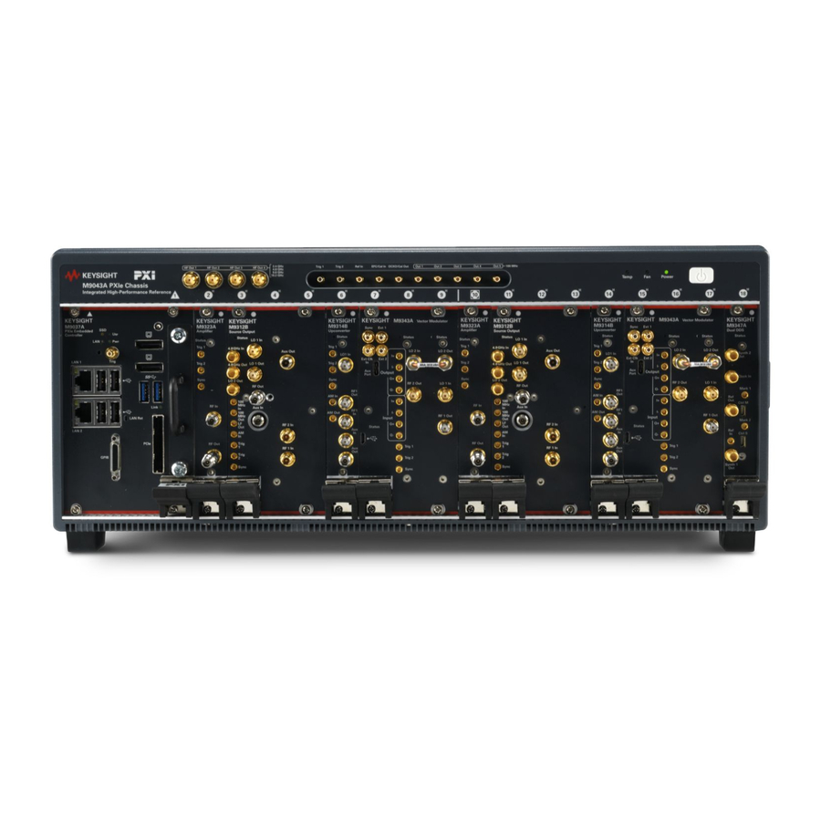
Page 43: Verify M9383B Vxg-M Shipment Contents
Verify M9383B VXG-m Shipment Contents The M9383B VXG-m is housed in a M9043A PXIe chassis. The M9383B VXG-m comes in two configurations: Single Channel and Dual Channel. The single channel configuration consists of the software, chassis, a Keysight M9037A Embedded... - Page 44 Step 1: Unpack, Inspect, and Verify Shipment Verify M9383B VXG-m Shipment Contents Keysight Part Description Number M9383-20044 Cable, semi-rigid, male connector (2.4 mm) - male connector (2.4 M9383-20045 Cable, semi-rigid, SMA (male) - APC male connector (3.5 mm) M9383-20047 Cable, semi-rigid, SMA (male) - SMA (male) M9383-20048 Cable, semi-rigid, SMA (male) - APC male connector (3.5 mm)
-
Page 45: Step 2: Download The Latest Documentation
For the worldwide contact information for repair and service, visit www.keysight.com/find/assist. To receive the latest updates by email, subscribe to Keysight Email Updates at the following URL: www.keysight.com/find/MyKeysight Information on preventing M9383B VXG-m damage can be found at:... - Page 46 This page has been intentionally left blank M9383B Startup Guide...
-
Page 47: Step 3: Prepare And Power Up The Signal Generator
M9383B VXG-m PXIe Microwave Signal Generator Startup Guide Step 3: Prepare and Power up the Signal Generator Before Powering up the Instrument Prepare and Power up the Instrument System Requirements Installed Software User Accounts Windows Configuration Configuring LAN Windows Security... -
Page 48: Chassis Air Flow
Cable and Connector Care When you need to disconnect push-on cables from the module front panel connectors, use the Keysight Cable Removal Tool (PN: 5002-3361) shown in the figure below provided in your Keysight PXIe instrument's ship kit. M9383B Startup Guide... - Page 49 Step 3: Prepare and Power up the Signal Generator Before Powering up the Instrument To avoid damage to the cables or connectors, pull the cable straight away from the connector.Do not use the tool as a pry bar. M9383B Startup Guide...
-
Page 50: Prepare And Power Up The Instrument
2. Make sure that the instrument fans are operable and free of dust and other contaminants that may restrict airflow. 3. Press the power button to power up the instrument. System Requirements System Requirements Monitor, and USB compatible keyboard and mouse Embedded controller Keysight M9037A embedded controller M9383B Startup Guide... -
Page 51: Installed Software
SYSTem:PDOWn Customer Installation of Software Installation of other Third Party Software The M9383B VXG-m platform is an Open Windows environment, so you can install software on the instrument. However, installation of non-approved software may affect instrument performance. M9383B Startup Guide... -
Page 52: User Accounts
User names are not case sensitive but passwords are case sensitive. It is Keysight’s expectation that each user’s My Documents folder is mapped to the D: drive. This is to avoid overwriting the user’s data in the event the Instrument... -
Page 53: Windows Configuration
Step 3: Prepare and Power up the Signal Generator Windows Configuration Recovery must be performed. Also, this facilitates convenient backup by copying the contents of the D: drive to external media. All user accounts created by the factory already have My Documents mapped to the D: drive. It is recommended to map all new users’... - Page 54 Step 3: Prepare and Power up the Signal Generator Windows Configuration You May Use This To Do This… Feature: Add the Instrument to a network Install and configure a printer Set the time and date Click Advanced system settingsto open the System Properties dialog. In this dialog, go to Advanced tab and clickSettings under Performance to open Performance Options dialog.
- Page 55 In addition, Do not: Add, delete, or modify disk drive partitions. Delete or modify Keysight registry entries. Change the contents of any directories containing the name "Keysight". Stop the IIS server Tamper with any virtual directories (or their contents) that come configured with the instrument.
-
Page 56: Configuring Lan
Step 3: Prepare and Power up the Signal Generator Configuring LAN Configuring LAN Hostname The Computer Name, or Hostname, is preconfigured from the factory. It must be a unique name such that it does not conflict with other equipment on your LAN. The preconfigured Computer Name is K-<model number>-xxxxx, where xxxxx is the last 5 digits of the instrument’s serial number. -
Page 57: Windows Security
LAN. Do not modify the default network settings as this may cause problems to the operating system of the M9383B VXG-m. The M9383B VXG-m is shipped with the Windows 10 firewall enabled and Windows Defender. You can... -
Page 58: Automatic Updates
To adjust Windows Defender settings, log in as an administrator (default password:"Keysight4u!"). Minimize the M9383B VXG-m application, click Start and type: defender. Click Windows Defender from the Best match column. Automatic Updates Microsoft recommends that you always get the latest critical Windows updates to ensure that the instrument's Windows operating system is protected. -
Page 59: System Restore
Customer Installation of Software for more information. While performing backups, Keysight recommends that you backup the data to an external storage device connected to the network or one of the instrument's USB connectors. Also, you should perform backups at times when the instrument is not being used for normal operations, as it may impact the instrument's overall performance. -
Page 60: Disk Drive Partitioning And Use
The E: partition is reserved for Keysight’s use. The primary use of the E: drive is for housing the Calibration and Alignment data. Do not change or overwrite the files on this drive. - Page 61 Step Notes 1. Make sure the instrument is turned off. 2. Turn on the instrument. After the Keysight Technologies screen is displayed, Press the Down Arrow key to move the highlight to Instru- This screen is displayed for five seconds.
- Page 62 Step 3: Prepare and Power up the Signal Generator Disk Drive Recovery Process Step Notes 3. When the Instrument Recovery System has booted, follow the on- screen instructions to recover the image of the C: drive. Press 2, then press Enter to select the recovery.
-
Page 63: Updating The Software (Required After A Recovery)
DO NOT turn off the instrument power at this time for ANY reason. If this process is interrupted, the instrument most likely needs to be sent back to an Keysight Service Center for servicing before it is usable again. -
Page 64: Using Windows Tools
Step 3: Prepare and Power up the Signal Generator Using Windows Tools Step The installation process can take up to 45 minutes. Do not turn the instrument power off or serious damage may occur. If any pop up windows appear, click OK or Ignore to proceed. 4. -
Page 65: Remote Desktop: Using The Signal Generator Remotely
Step 3: Prepare and Power up the Signal Generator Using Windows Tools Key Presses Actions Moves focus/control to the pull down menus bar in the active Window Right Arrow In pull-down menu: opens the next menu to the right, or opens a submenu In a dialog box: selects an option button Left Arrow In pull-down menu: opens the next menu to the left, or opens a submenu... -
Page 66: Overview Of Remote Desktop Operation
Step 3: Prepare and Power up the Signal Generator Using Windows Tools Overview of Remote Desktop Operation Using the Remote Desktop functionality of the instrument allows you to control and interact with the instrument from a remote computer. When the instrument is configured for remote connectivity, and a separate computer is configured to act as a Remote Desktop Host, you can send commands to the instrument from the remote computer, and you can see the instrument display on the screen of the remote computer. -
Page 67: How To Locate The Computer Name Of The Instrument
Connectivity. However, you need to have a Windows installation CD-ROM available to run the Client software. The following instructions relate to software provided by Microsoft Corporation. Keysight offers no warranty regarding the operation of such software. The procedure described here may be changed by Microsoft at some future time. -
Page 68: Running A Remote Desktop Session
Step 3: Prepare and Power up the Signal Generator Using Windows Tools Locating the Name from the Windows Desktop (with a mouse) Step Notes 1. Click Start > Control Panel. 2. Double-click System The computer name is listed in the Computer name, domain, and workgroup settings section. - Page 69 Step 3: Prepare and Power up the Signal Generator Using Windows Tools Only the current User or an Administrator can remotely log into the instrument. To see who the current user of the instrument is, press Ctrl+Esc on the instrument until you can view the current user name on the Start menu.
- Page 70 Step 3: Prepare and Power up the Signal Generator Using Windows Tools Step Notes 3. Click the Display tab. Under Display configuration, you may select the size of the window in which the instru- ment display appears. Do not select any size smaller than the instrument’s front panel dis- play.
-
Page 71: Windows Shortcuts And Miscellaneous Tasks
Step 3: Prepare and Power up the Signal Generator Using Windows Tools Step Notes Ending a Remote Desktop session There are two ways to disconnect the remote computer from the instrument, ending the session: Step Notes 1. Click X and then click OK. For full-screen, X appears at the top center of the window. - Page 72 Step 3: Prepare and Power up the Signal Generator Using Windows Tools Windows Shortcut Key Combinations To do the following: Press: Display the Windows Start Menu Ctrl+Esc Cycle through all open applications Alt+Tab Select the first menu of a menu bar Move through menu headings Left Arrow, Right Arrow Open (drop down) a menu...
-
Page 73: Trigger Routing
Click OK. This applies the change and closes the dialog box. Trigger Routing The M9383B VXG-m supports the following triggering modes for starting modulation. Immediate (Default) Modulation begins as soon as the Vector Modulator is ready. External Triggering Can be used for synchronization with an external trigger source for starting waveform playback. - Page 74 This page has been intentionally left blank M9383B Startup Guide...
-
Page 75: Step 4: Verify Operation Of The Signal Generator
M9383B VXG-m PXIe Microwave Signal Generator Startup Guide Step 4: Verify Operation of the Signal Generator In this step, the operation of the M9383B VXG-m is verified. Before running the verification procedure, ensure that the instrument is powered on, and all cabling is correct. Refer to Recommended Configurations for proper cabling. -
Page 76: Conduct A Self Test
Step 4: Verify Operation of the Signal Generator Conduct a Self Test Conduct a Self Test To verify the operation of the M9383B VXG-m, conduct a Self Test. Before running a Self Test, make sure that the instrument is powered on, and all cabling is correct. -
Page 77: Step 5: Generate And View An Output Signal
1. Power on the Keysight Signal Analyzer. 2. Connect a high-quality male (2.4 mm) to SMA (male) cable between the RF Out connector on the M9323A Amplifier and the RF In connector on the Keysight Sig- nal Analyzer. 3. Torque the connectors to 8 In-lb (0.904 Nm). - Page 78 Step 5: Generate and View an Output Signal 5. On the Keysight Signal Analyzer, select AUTO TUNE in the Frequency menu. You should see the following display on your Keysight Signal Analyzer. Repeat the above steps for a M9383B VXG-m with dual channel configuration.
-
Page 79: Step 6: Installation Is Complete
M9383B VXG-m PXIe Microwave Signal Generator Startup Guide Step 6: Installation is Complete Proceed to program your product by means of the SCPI programming interface. ... - Page 80 This page has been intentionally left blank M9383B Startup Guide...
- Page 81 This information is subject to change without notice. © Keysight Technologies 2019 Edition 1.0, June, 2019 M9384-90003 www.keysight.com...
Need help?
Do you have a question about the M9383B VXG-m and is the answer not in the manual?
Questions and answers