Sign In
Upload
Download
Table of Contents
Contents
Add to my manuals
Delete from my manuals
Share
URL of this page:
HTML Link:
Bookmark this page
Add
Manual will be automatically added to "My Manuals"
Print this page
×
Bookmark added
×
Added to my manuals
Manuals
Brands
Keysight Manuals
Inverter
N3300A
User manual
Keysight N3300A User Manual
Dc electronics loads
Hide thumbs
1
2
3
4
5
6
7
Table Of Contents
8
9
10
11
12
13
14
15
16
17
18
19
20
21
22
23
24
25
26
27
28
29
30
31
32
33
34
35
36
37
38
39
40
41
42
43
44
45
46
47
48
49
50
51
52
53
54
55
56
57
58
59
60
61
62
63
64
65
66
67
68
69
70
71
72
73
74
75
76
77
78
79
80
81
82
83
84
85
86
87
88
89
90
91
92
93
94
95
96
97
98
99
100
101
102
103
104
105
106
107
108
page
of
108
Go
/
108
Contents
Table of Contents
Bookmarks
Table of Contents
Warranty Information
Safety Summary
Declaration of Conformity
Acoustic Noise Information
Printing History
Table of Contents
Quick Reference
The Front Panel -At a Glance
The Rear Panel at a Glance
Instrument Configuration
Front Panel Number Entry
Front Panel Annunciators
Immediate Action Keys
Front Panel Menus - at a Glance
SCPI Programming Commands - at a Glance
General Information
Document Orientation
Safety Considerations
Options and Accessories
Description
Features and Capabilities
Front Panel Controls
Remote Programming
Operating Modes
Constant Current CC (Mode)
Constant Resistance (CR) Mode
Constant Voltage (CV) Mode
Transient Operation
List Operation
Triggered Operation
Input Control
Protection Features
Saving and Recalling Settings
External Control Signals
Remote Sensing
Monitor Outputs
External Programming Input
Fault
Port On/Off
Input Measurements
DC Measurements
RMS Measurements
Minimum and Maximum Measurements
Power Measurements
Measurement Ranges
Installation
Inspection
Damage
Packaging Material
Items Supplied
Cleaning
Installing the Modules
Procedure
Channel Number
Location
Bench Operation
Rack Mounting
Input Connections
Power Cord
Manually-Tightened Connectors
8Mm Screw Terminal Connector (Option UJ1)
Wire Considerations
Control Connector
Sense Switch
Trigger and Digital Connections
Computer Connections
GPIB Interface
RS-232 Interface
Application Connections
Local Sense Connections
Remote Sense Connections
Parallel Connections
Low Voltage Operation
Turn-On Checkout
Introduction
Checkout Procedure
In Case of Trouble
Error Messages
Selftest Errors
Front Panel Operation
Introduction
Front Panel Description
System Keys
Function Keys
Immediate Action Keys
Scrolling Keys
Metering Keys
Input Control Keys
Transient Control Keys
Trigger Control Keys
List Control Keys
Entry Keys
Examples of Front Panel Programming
Using the Front Panel Display
Programming Constant Current, Voltage and Resistance Modes
Programming Transient Operation
Programming Lists
Querying and Clearing Output Protection and Errors
Making Basic Front Panel Measurements
Setting the GPIB Address
Storing and Recalling Instrument States
Specifications
Performance Test and Calibration Procedures
Introduction
Equipment Required
Performance Tests
IMON Zero Verification
CC Mode Tests
CV Mode Tests
CR Mode Tests
Keysight N3302A Verification Test Record
Keysight N3303A Verification Test Record
Keysight N3304A Verification Test Record
Keysight N3305A Verification Test Record
Keysight N3306A Verification Test Record
Keysight N3307A Verification Test Record
Calibration
Parameters Calibrated
IMON, IPROG and CURRENT Calibration Program
VOLTAGE Calibration Program
RESISTANCE Calibration Program
Index
Advertisement
Quick Links
Download this manual
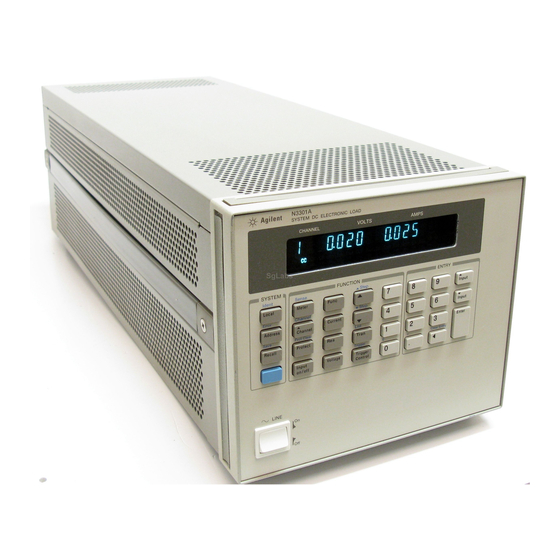
Keysight DC
Electronics Loads
Models N3300A, N3301A, N3302A, N3303A
N3304A, N3305A, N3306A, and N3307A
User's Guide
Table of
Contents
Previous
Page
Next
Page
1
2
3
4
5
Advertisement
Table of Contents
Need help?
Do you have a question about the N3300A and is the answer not in the manual?
Ask a question
Questions and answers
Related Manuals for Keysight N3300A
Control Unit Keysight N3304A Component Level Information
(40 pages)
Inverter Keysight N5171B EXG Service Manual
X-series signal generators (276 pages)
Inverter Keysight N3301A User Manual
Dc electronics loads (108 pages)
Inverter Keysight N3306A User Manual
Dc electronics loads (108 pages)
Inverter Keysight 81150A User Manual
Pulse function arbitrary noise generator (672 pages)
Inverter Keysight E8267D User Manual
Psg signal generators (358 pages)
Inverter Keysight M8195A User Manual
Arbitrary waveform generator revision 2 (268 pages)
Inverter Keysight M9384B Startup Manual
Vxg microwave signal generator (64 pages)
Inverter Keysight M8194A User Manual
120 gsa/s arbitrary waveform generator (172 pages)
Inverter Keysight M9383B VXG-m Startup Manual
Pxie microwave signal generator (81 pages)
Inverter Keysight M9099 Startup Manual
Waveform creator 3.2 (26 pages)
Inverter Keysight U2761A User Manual
Usb modular function/arbitrary waveform generator (105 pages)
Inverter Keysight M9380A Startup Manual
Pxie vector signal generator 1 mhz to 3 ghz or 6 ghz (45 pages)
This manual is also suitable for:
N3301a
N3303a
N3304a
N3305a
N3306a
N3307a
...
Show all
N3302a
Table of Contents
Save PDF
Print
Rename the bookmark
Delete bookmark?
Delete from my manuals?
Login
Sign In
OR
Sign in with Facebook
Sign in with Google
Upload manual
Upload from disk
Upload from URL


Need help?
Do you have a question about the N3300A and is the answer not in the manual?
Questions and answers