Sign In
Upload
Download
Table of Contents
Contents
Add to my manuals
Delete from my manuals
Share
URL of this page:
HTML Link:
Bookmark this page
Add
Manual will be automatically added to "My Manuals"
Print this page
×
Bookmark added
×
Added to my manuals
Manuals
Brands
Insportline Manuals
Home Gym
16636
User manual
Insportline 16636 User Manual
Hide thumbs
1
Table Of Contents
2
3
4
5
6
7
8
9
10
11
12
13
14
15
16
page
of
16
Go
/
16
Contents
Table of Contents
Bookmarks
Table of Contents
Table of Contents
Safety Precautions
Product Description
Hardware Identification Chart
Assembly Steps
Operational Instructions
Using the Fitness Meter
Functions
How to Install and Replace Batteries
Operational Instructions
Load Adjustment
Pedal Strap Adjustment
Maintenance
Storage
Folding the Rowing Machine
Warm-Up and Cool-Down
Warm-Up Phase
Stretching
Cool-Down Phase
Product Drawing
Parts List
Terms and Conditions of Warranty, Warranty Claims
Advertisement
Quick Links
1
Assembly Steps
Download this manual
USER MANUAL – EN
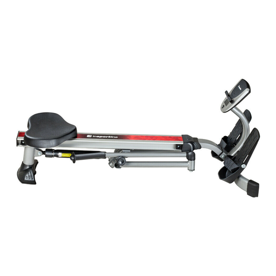
IN 16636 Rowing Machine inSPORTline Power Master X
Table of
Contents
Previous
Page
Next
Page
1
2
3
4
5
Advertisement
Table of Contents
Need help?
Do you have a question about the 16636 and is the answer not in the manual?
Ask a question
Questions and answers
Related Manuals for Insportline 16636
Home Gym Insportline 1336 User Manual
(8 pages)
Home Gym Insportline Yukona User Manual
(20 pages)
Home Gym Insportline Yukona User Manual
(22 pages)
Home Gym Insportline Yakapa User Manual
(34 pages)
Home Gym Insportline Ocean User Manual
(15 pages)
Home Gym inSPORTline IN 724 User Manual
Multifunction trainer insportline athlet (24 pages)
Home Gym Insportline IN465 User Manual
Insportline rower power master user's manual (10 pages)
Home Gym Insportline IN 1920 User Manual
Air magnetic rower insportline river (44 pages)
Home Gym Insportline ProfiGym C100 User Manual
(25 pages)
Home Gym Insportline IN 26050 User Manual
(15 pages)
Home Gym Insportline BR-3010 User Manual
In 2810 – rowing machine rio (18 pages)
Home Gym Insportline IN 14953 User Manual
(21 pages)
Home Gym Insportline ProfiGym C95 User Manual
(22 pages)
Home Gym Insportline RW60 User Manual
(15 pages)
Home Gym Insportline RowAir User Manual
(40 pages)
Home Gym Insportline Ocean IN 1979 Manual
(11 pages)
This manual is also suitable for:
Power master x
Table of Contents
Print
Rename the bookmark
Delete bookmark?
Delete from my manuals?
Login
Sign In
OR
Sign in with Facebook
Sign in with Google
Upload manual
Upload from disk
Upload from URL


Need help?
Do you have a question about the 16636 and is the answer not in the manual?
Questions and answers