Table of Contents
Advertisement
Centrometal d.o.o. - Glavna 12, 40306 Macinec, Croatia, tel: +385 40 372 600, fax: +385 40 372 611
Technical instructions
using of REGULATION
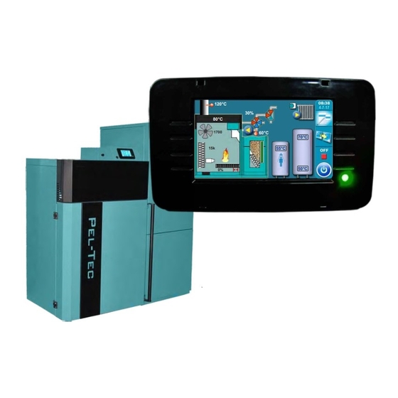
hot water boiler PelTec / PelTec-lambda
READY
THE FIRST START-UP MUST BE DONE BY AUTHORIZED PERSON
OTHERWISE PRODUCT WARRANTY IS NOT VALID
HEATING TECHNIQUE
PelTec-lambda 12-48
120°C
O2=8%
30%
80°C
1700
60°C
15k
55°C
0%
PelTec 12-48
70°C
50°C
Advertisement
Table of Contents

Subscribe to Our Youtube Channel
Related Manuals for Centrometal PelTec 12-48


Summary of Contents for Centrometal PelTec 12-48
- Page 1 HEATING TECHNIQUE Centrometal d.o.o. - Glavna 12, 40306 Macinec, Croatia, tel: +385 40 372 600, fax: +385 40 372 611 Technical instructions using of REGULATION hot water boiler PelTec / PelTec-lambda 120°C O2=8% 80°C READY 1700 60°C 70°C 55°C 50°C...
- Page 2 Screen SWITCHING ON After turning on the main switch, screen will display language selection menu and software version. You can choose between 12 languages, Croatian, French, Portuguese, English, Slovenian, Italian, Serbian, German, Czech,Hungarian, Slovakian and Spanish. To select the language, press the flag of language you want.
-
Page 3: Main Menu, Buttons
Main Menu, Buttons MAIN MENU The main menu is used to select the desired submenu. To select a specific menu you must press the appropriate icon on the screen. To switch between the ’’Main menu’’ and ’’Boiler working display’’ press the button ’’Display selection’’. To switch between graphic and numeric display of the boiler using press ’’Boiler operation display’’. -
Page 4: Screen, Symbols
Screen, Symbols SYMBOLS 120°C O2=8% 80°C 1700 60°C 1 - Boiler 12 - Pellet level in the tank (3 levels) 2 - Pellet tank 13 - Boiler temperature sensor 3 - Pellet feeding screw 14 - Flue gas sensor 4 - 4-way mixing valve with motor device 15 - Flow temperature sensor (when working, left/right arrow will be shown) 16 - Resistance of photocell (luminous intensity... - Page 5 Screen, Symbols SYMBOLS 4-way mixing valve with motor device 60°C 60°C 60°C Motor device doesn’t work Motor device is closing Motor device is opening the valve the valve Pellet feeding screw Pellets falling Feeding screw Pellet feeding screw is working Pellet feeding screw doesn’t work (pellets are falling and screw is moving) Flame symbol...
- Page 6 Symbols, Configuration symbols Pellet level in the tank (3 levels) Position of burner grate Closed (ready to work) Open (cleaning) 100% Half-empty Full Empty - error - warning CONFIGURATION SYMBOLS 05:08 120°C O2=8% 80°C 1700 60°C The following symbols are shown on the display configuration (page 4, mark 20 in the figure) Pump (when pump is working symbol is rotating, otherwise idle) The pump has a request for work (next to the pump symbol bright yellow square when...
- Page 7 Configuration symbols 60°C Room thermostat Hydraulic crossover with the current temperature Next to the room thermostat symbol bright blue circle (the room thermostat has requested for operating the pump, the pump does not work if you have not met all the conditions for its operation, 70°C for example.
-
Page 8: Maintenance
Maintenance, Cleaning the boiler 1.0. MAINTENANCE 1. Maintenance Manual B.Cleaning Filling screw transp. System Airvent 1.1. CLEANING THE BOILER Cleaning the boiler - By pressing the button ’’START’’ (1) fan will begin work (2), an burner grate (3) will move into the open position (100%) (4), (button ’’START’’ will become a button’’STOP’’). This option enables you to during cleaning of combustion chamber, boiler ash does not come out of the boiler, and since the burner grate is open ash falls into the ash box. - Page 9 Filling at start, System airvent 1.2. FILLING AT START Filling at start - by pressing ''START'' (1) pellet feeding screw starts to operate (2) (works 25 min), and the burner grate (3) moves to the open position (100%) (4) to make pellets fell down in ashtray After this process is complete pellet feeding screw stops working, the burner grate is returned to the closed position (0%) (4).
-
Page 10: On The Screen
Temperatures 2.0. TEMPERATURE Temperatures choice depends on the configuration of heating. Below are shown all types of installation and configuration. CONFIGURATION 1 - DOMESTIC HOT WATER (DHW) Scheme of configuration Scheme 1. Configuration DHW Required sensors: - return flow temp. sensor - DHW sensor 1 - Boiler PelTec / PelTec-lambda 5 - Return flow temperature sensor... - Page 11 Temperature (configuration DHW) 2. TEMPERATURES (CONFIGURATION DHW) 2. Temperature DHW temp. Differential of DHW 2.1 TEMPERATURE DHW Possible selection: default: 50°C Minimum: 40°C Maximum: 80°C Temperature setting options of DHW (domestic hot water). 2.2 DIFFERENCE DHW Possible selection: default: 5°C Minimum: 4°C Maximum: 40°C...
- Page 12 Temperature (configuration DHC) CONFIGURATION 2 - DIRECT HEATING CIRCUIT (DHC) Scheme of configuration Scheme 2. Configuration DHC Required sensors: - return flow temp. sensor - flow temperature sensor 1 - Boiler PelTec / PelTec-lambda 5 - Return flow temperature sensor 2 - Air self-venting group 2,5 bar 6 - Flow temperature sensor 3 - Motor 4-ways mixing valve...
-
Page 13: Flow Temperature
Temperature (configuration DHC) 2. TEMPERATURE (CONFIGURATION DHC) 2. Temperature Main flow temp. 2.1 FLOW TEMPERATURE Possible selection: default: 60°C Minimum: 30°C Maximum: 90°C The possibility of setting flow temperature Technical instructions REGULATION PelTec / PelTec-lambda... - Page 14 Temperature (domestic hot water and direct heating circuit) CONFIGURATION 3 - DHW || DHC Scheme of configuration Scheme 3. Configuration DHC || DHW Required sensors: - return flow temp. sensor - flow temperature sensor - DHW sensor 1 - Boiler PelTec / PelTec-lambda 6 - Flow temperature sensor 2 - Air self-venting group 2,5 bar 7 - DHW tank...
- Page 15 Temperature (configuration DHW || DHC) 2. TEMPERATURE (CONFIGURATION DHW || DHC) 2. Temperature DHW temp. Differential of DHW Main flow temp. 2.1 TEMPERATURE DHW Possible selection: default: 50°C Minimum: 40°C Maximum: 80°C Temperature setting options of DHW (domestic hot water). 2.2 DIFFERENTIAL OF DHW Possible selection: default:...
- Page 16 Temperature (configuration accumulation tank) CONFIGURATION 4 - ACCUMULATION TANK Scheme of configuration Scheme 4. Configuration BUF Required sensors: - return flow temp. sensor - accumulation tank sensor (upper) - accumulation tank sensor (lower) 1 - Boiler PelTec / PelTec-lambda 5 - Back flow temperature sensor 2 - Air self-venting group 2,5 bar 6 - Accumulation tank CAS 3 - Motor 4-ways mixing valve...
- Page 17 Temperature (configuration BUF) 2. TEMPERATURE (CONFIGURATION BUF) 2. Temperature Buffer tank temp. Min buf.tank temp. Diff.buf.tank temp. 2.1 TEMPERATURE OF THE ACCUMULATION TANK Possible selection: default: 80°C Minimum: 40°C Maksimum: 85°C The possibility of setting the desired temperature of the accumulation tank. 2.2 MINIMUM TEMPERATURE OF THE ACCUMULATION TANK Possible selection: default:...
- Page 18 Temperature (domestic hot water and accumulation tank) CONFIGURATION 5 - DHW||BUF Scheme of configuration Scheme 5. Configuration DHW || BUF Required sensors: - return flow temp. sensor - DHW tank sensor - accumulation tank sensor (upper) - accumulation tank sensor (lower) 1 - Boiler PelTec / PelTec-lambda 7 - DHV tank sensor 2 - Air self-venting group 2,5 bar...
- Page 19 Temperature (domestic hot water and accumulation tank) 2. TEMPERATURE (CONFIGURATION DHW || BUF) 2. Temperature Buffer tank temp. Differential of DHW Min buf.tank temp. Dif.buf.tank temp. DHW temp. 2.1 TEMPERATURE OF THE ACCUMULATION TANK Possible selection: default: 80°C Minimum: 40°C Maksimum: 85°C The possibility of setting the desired temperature of the accumulation tank.
- Page 20 Temperature (domestic hot water and accumulation tank) 2.4 TEMPERATURE DHW Possible selection: default: 50°C Minimum: 40°C Maximum: 80°C Temperature setting options of DHW (domestic hot water). 2.5 DIFFERENCE DHW Possible selection: default: 5°C Minimum: 4°C Maximum: 40°C The possibility of setting domestic hot water diference. Technical instructions REGULATION PelTec / PelTec-lambda...
- Page 21 Temperature (accumulation tank--indirect heating circuit) CONFIGURATION 6 - BUF--IHC Scheme of configuration Scheme 6. Configuration BUF -- IHC Required sensors: - return flow temp. sensor - accumulation tank sensor (upper) - accumulation tank sensor (lower) 1 - Boiler PelTec / PelTec-lambda 6 - Accumulation tank CAS 2 - Air self-venting group 2,5 bar 7 - Accumulation tank sensor CAS 1 (upper)
- Page 22 Temperature (accumulation tank--indirect heating circuit) 2. TEMPERATURE (CONFIGURATION BUF--IHC) 2. Temperature Buffer tank temp. Min buf.tank temp Diff. buf. tank temp. 2.1 TEMPERATURE OF THE ACCUMULATION TANK Possible selection: default: 80°C Minimum: 40°C Maksimum: 85°C The possibility of setting the desired temperature of the accumulation tank. 2.2 MINIMUM TEMPERATURE OF THE ACCUMULATION TANK Possible selection: default:...
- Page 23 Temperature (configuration DHW || BUF--IHC) CONFIGURATION 7 - DHW || BUF--IHC Scheme of configuration Scheme 7. Configuration DHW || BUF -- IHC Required sensors: - return flow temp. sensor - DHW tank sensor - accumulation tank sensor (upper) - accumulation tank sensor (lower) 1 - Boiler PelTec / PelTec-lambda 8 - Accumulation tank CAS 2 - Air self-venting group 2,5 bar...
- Page 24 Temperature (configuration DHW || BUF--IHC) TEMPERATURE (KONFIGURACIJA AKU--IKG) 2. TEMPERATURE (CONFIGURATION DHW || BUF--IHC) 2. Temperature Buffer tank temp. Differential of DHW Min buf.tank. temp. Dif.buf.tank temp DHW temp. 2.1 TEMPERATURE OF THE ACCUMULATION TANK Possible selection: default: 80°C Minimum: 40°C Maksimum: 85°C The possibility of setting the desired temperature of the accumulation tank.
- Page 25 Temperature (configuration DHW || BUF--IHC) 2.4 TEMPERATURE DHW Possible selection: default: 50°C Minimum: 40°C Maximum: 80°C Temperature setting options of DHW (domestic hot water). 2.5 DIFFERENCE DHW Possible selection: default: 5°C Minimum: 4°C Maximum: 40°C The possibility of setting domestic hot water diference. Technical instructions REGULATION PelTec / PelTec-lambda...
- Page 26 Temperature (configuration BUF--DHW) KONFIGURATION 8 - BUF-- DHW Scheme of configuration Scheme 8. Configuration BUF -- DHW Required sensors: - return flow temp. sensor - DHW tank sensor - accumulation tank sensor (upper) - accumulation tank sensor (lower) 1 - Boiler PelTec / PelTec-lambda 6 - Accumulation tank CAS 2 - Air self-venting group 2,5 bar 7 - Accumulation tank sensor CAS 1 (upper)
- Page 27 Temperature (configuration BUF--DHW) TEMPERATURE (KONFIGURACIJA AKU--IKG) 2. TEMPERATURE (CONFIGURATION BUF--DHW) 2. Temperature Buffer tank temp. Differential of DHW Min buf.tank. temp. Dif.buf.tank temp DHW temp. 2.1 TEMPERATURE OF THE ACCUMULATION TANK Possible selection: default: 80°C Minimum: 40°C Maksimum: 85°C The possibility of setting the desired temperature of the accumulation tank. 2.2 MINIMUM TEMPERATURE OF THE ACCUMULATION TANK Possible selection: default:...
- Page 28 Temperature (configuration BUF--DHW) 2.4 TEMPERATURE DHW Possible selection: default: 50°C Minimum: 40°C Maximum: 80°C Temperature setting options of DHW (domestic hot water). 2.5 DIFFERENCE DHW Possible selection: default: 5°C Minimum: 4°C Maximum: 40°C The possibility of setting domestic hot water diference. Technical instructions REGULATION PelTec / PelTec-lambda...
- Page 29 Temperature (configuration BUF--IHC || DHW) CONFIGURATION 9 - BUF -- IHC|| DHW Scheme of configuration Scheme 9. Configuration BUF -- IHC || DHW Required sensors: - return flow temp. sensor - DHW tank sensor - accumulation tank sensor (upper) - accumulation tank sensor (lower) 1 - Boiler PelTec / PelTec-lambda 8 - Accumulation tank sensor CAS 2 (lower) 2 - Air self-venting group 2,5 bar...
- Page 30 Temperature (configuration BUF--IHC || DHW) TEMPERATURE (KONFIGURACIJA AKU--IKG) 2. TEMPERATURE (CONFIGURATION BUF--IHC || DHW) 2. Temperature Buffer tank temp. Differential of DHW Min buf.tank. temp. Dif.buf.tank temp DHW temp. 2.1 TEMPERATURE OF THE ACCUMULATION TANK Possible selection: default: 80°C Minimum: 40°C Maksimum: 85°C The possibility of setting the desired temperature of the accumulation tank.
- Page 31 Temperature (configuration BUF--IHC || DHW ) 2.4 TEMPERATURE DHW Possible selection: default: 50°C Minimum: 40°C Maximum: 80°C Temperature setting options of DHW (domestic hot water). 2.5 DIFFERENCE DHW Possible selection: default: 5°C Minimum: 4°C Maximum: 40°C The possibility of setting domestic hot water diference. Technical instructions REGULATION PelTec / PelTec-lambda...
- Page 32 Temperature (configuration hidraulic crossover) CONFIGURATION 10 - HIDRAULIC CROSSOVER (CRO) Scheme of configuration Scheme 10. Configuration CRO Required sensors: - return flow temp. sensor - hydraulic crossover sensor 1 - Boiler PelTec / PelTec-lambda 5 - Return flow temperature sensor 2 - Air self-venting group 2,5 bar 6 - Hydraulic crossover 3 - Motor 4-ways mixing valve...
- Page 33 Temperature (configuration CRO) TEMPERATURE (KONFIGURACIJA AKU--IKG) 2. TEMPERATURE (CONFIGURATION HIDRAULIC CROSSOVER) 2. Temperature Crossover temp. 2.1 TEMPERATURE OF HIDRAULIC CROSSOVER Possible selection: default: 80°C Minimum: 70°C Maksimum: 85°C The possibility of setting the hydraulic crossover temperature. Technical instructions REGULATION PelTec / PelTec-lambda...
- Page 34 Temperature (configuration hidraulic crossover or accumulation tank) CONFIGURATION 11 - (CRO / BUF) (used only in cascades and external start) Scheme of configuration Scheme 11. Configuration CRO / BUF Version 1: (display shows 1 temperature, eg. hidraulic crossover) Version 2: (Display shows 2 temperatures (eg. accumulation tank) 1 - Boiler PelTec / PelTec-lambda 6a - Hydraulic crossover 2 - Air self-venting group 2,5 bar...
-
Page 35: Maximum Boiler Temperature
Temperature (hidraulic crossover or accumulation tank) TEMPERATURE (KONFIGURACIJA AKU--IKG) 2. TEMPERATURE (CONFIGURATION CRO/BUF) 2. Temperature Max. boiler. temp 2.1 MAXIMUM BOILER TEMPERATURE Possible selection: default: 80°C Minimum: 70°C Maksimum: 85°C The possibility of setting the hydraulic crossover temperature. Technical instructions REGULATION PelTec / PelTec-lambda... - Page 36 Temperature (domestic hot water and direct heating circuit (second version) CONFIGURATION 12 - DHW || DHC (2) Scheme of configuration Scheme 12. Configuration DHC || DHW (2) Required sensors: - return flow temp. sensor - flow temperature sensor - DHW sensor 1 - Boiler PelTec / PelTec-lambda 6 - Flow temperature sensor 2 - Air self-venting group 2,5 bar...
-
Page 37: Flow Temperature
Temperature (configuration DHW || DHC (2)) 2. TEMPERATURE (CONFIGURATION DHW || DHC(2)) 2. Temperature DHW temp. Differential of DHW Main flow temp. 2.1 TEMPERATURE DHW Possible selection: default: 50°C Minimum: 40°C Maximum: 80°C Temperature setting options of DHW (domestic hot water). 2.2 DIFFERENCE DHW Possible selection: default:... - Page 38 Temperatures (2 direct heating circuits) CONFIGURATION 13 - DHC 2X Scheme of configuration Scheme 13. Configuration DHC 2X 2. heating circuit 1. heating circuit Required sensors: - return flow temp. sensor - main flow temperature sensor 7 - Heating circuit 1 1 - Boiler PelTec / PelTec-lambda 8 - 3-way manual mixing valve 1.circuit 2 - Air self-venting group 2,5 bar...
- Page 39 Temperatures (configuration DHC 2X) 2.0 TEMPERATURES (CONFIGURATION DHC 2X) 2. Temperature Main flow temp. 2.1 FLOW TEMPERATURE Possible selection: default: 60°C Minimum: 30°C Maximum: 90°C The possibility of setting flow temperature Technical instructions REGULATION PelTec / PelTec-lambda...
- Page 40 Temperatures (accumulation tank -- 2 indirect heating circuits) CONFIGURATION 14 - AKU--IKG 2X Scheme of configuration Scheme 14. Configuration BUF--IHC 2X Required sensors: - return flow temp. sensor - accumulation tank sensor (upper) - accumulation tank sensor (lower) 2. heating circuit 1.
- Page 41 Temperatures (accumulation tank -- 2 indirect heating circuits) TEMPERATURE (KONFIGURACIJA AKU--IKG) TEMPERATURE CONFIGURATION BUF--IHC2X) 2. Temperature Buffer tank temp. Min buf.tank temp Diff. buf. tank temp. 2.1 TEMPERATURE OF THE ACCUMULATION TANK Possible selection: default: 80°C Minimum: 40°C Maksimum: 85°C The possibility of setting the desired temperature of the accumulation tank.
- Page 42 Temperatures (hydraulic crossover -- domestic hot water) CONFIGURATION 15 - CRO--PTV Scheme of configuration Scheme 15. Configuration CRO--PTV Required sensors: - return flow temp. sensor - DHW tank sensor - hydraulic crossover sensor 1 - Boiler PelTec / PelTec-lambda 6 - Hydraulic crossover 2 - Air self-venting group 2,5 bar 7 - Hydraulic crossover sensor 3 - Motor 4-ways mixing valve...
- Page 43 Temperature (configuration CRO -- DHW ) 2. TEMPERATURE (CONFIGURATION CRO -- DHWD) 2. Temperature Crossover temp. DHW temp. Differential of DHW 2.1 TEMPERATURE OF HIDRAULIC CROSSOVER Possible selection: default: 80°C Minimum: 70°C Maksimum: 85°C The possibility of setting the hydraulic crossover temperature. 2.2 TEMPERATURE DHW Possible selection: default:...
- Page 44 Schedule 3.0. SCHEDULE 3. SCHEDULE Schedule Table 1 Table 2 Table 3 3.1. Schedule Default: Disable Disable Disable Table 2 Table 1 Table 3 3.1. SCHEDULE Possible selection: Disable - Schedule is turned off (default) Table 1 - Scheduled starting times are turned-on and work according to the settings in Table 1 Table 2 - Scheduled starting times are turned-on and work according to the settings in Table 2 Table 3 - Scheduled starting times are turned-on and work according to the settings in Table 3 ALWAYS WHEN SCHEDULE IS ENABLED (TABLE 1,2 OR 3)
- Page 45 Schedule 3.2. - 3.4. TABLE 1, 2, 3 Possibility of schedule is done using tables They can be pre-set 3 tables of schedule of which only one table can be active It is possible for every day of the week set 3 turning-on and 3 turning-off the boiler.
- Page 46 History 4.0. HISTORY Error list / warnings used in order to have an insight into the errors / warnings that have occurred. Written is: time of occurrence errors / warnings, error code / warning; description of the error / warning. The first press on the field error / warning field error / warnings is indicated, in addition to see and date generated errors / warnings.The History second press on the selected error / warning, prints a detailed description of the error...
- Page 47 History Boiler status: Boiler go to phases S7, C0 and OFF (it’s appear after I8 notice and completion of adjusted retry ignition number). Pellet supply tube E8-1 Possible causes: Feeding tube temperature is higher than temperature too high 80°C, interruption on el. connections between bimetal sensor and boiler, connection to boiler, cold connection or invalid bimetal sensor.
- Page 48 History Boiler status: Boiler go to phases S7, C0 and OFF. Fuel level Flame disappeared in Boiler status: Boiler immediate go to phase OFF. ignition phase Flame disappeared Boiler status: Boiler immediate go to phase OFF.. stabilization phase Hydra. switch sensor Boiler status: Boiler immediate go to phase OFF.
- Page 49 Operation Errors of additional equipment: Pelet suction system Boiler status: Boiler work normally. The problem occurs in The flap is not closed the work of additional equipment - "pellet suction system" if installed. Possible causes: Check if the flap is blocked with pellets , if the sensor is soiled with dust, if the sensor is about 1 mm distant from the flap, if the sensor reacts on the flap ( the LED lamp is switching on the sensor ).
-
Page 50: Operation
Operation 5.0. OPERATION 5. Operation DHW / Heating Flue pass. Cleaner Manual test Alarm Chimney sweep Pump protection Forced shutdown Internet supervision 5.1. DHW/HEATING* Possible selection: DHW+ Heating - boiler works as needed for heating and domestic hot water Only DHW - boiler works only when there is demand for domestic hot water *DHW priority- boiler works as needed for heating and DHW but with DHW priority ** Heating only- boiler works only when there is demand for heating (possible only on conf. -
Page 51: Manual Test
Manual test 5.2. MANUAL TEST Manual test is an option which enables testing of all parts of the boiler in order to check their technical accuracy. 5.2. Manual test Flue pass. Cleaner Grate cleaner Feeder screw Electric Heater 5.2. Manual test Valve closing Flue pass. - Page 52 Manual test 5.2.1. FAN Possible selection: START 1700 rpm - fan speed must be 1700 rpm START MAX - fan speed must be on maximun (cca. 2800 rpm) It is necessary to press the ''START'' next to the corresponding symbols and check if the fan operates according to the selected option (1700 rpm or cca.
-
Page 53: Electric Heater
Manual test 5.2.8. ELECTRIC HEATER This option allows you to check electric heater. It is necessary to press the ''START'' next to the corresponding symbol and check if the electric heater is working. After pressing the'' STOP'' electric heater will stop working. Each time you press'' 'START'' it becomes ''STOP'' and vice versa. -
Page 54: Chimney Sweeper
Manual test 5.3. CHIMNEY SWEEPER This option allows the flue gas measurement at different boiler powers. When this option is turned on, counter will appear on display. Time will start counting when the boiler reaches selected power (Dx). Text of the counter is red. When the boiler reach the selected power (Dx) and is on selected power for set time and factory set temperature of the boiler is achieved counter turns green and flue gases can be measured. - Page 55 Chimney sweeper The factory set temperature that must be achieved to start measuring (except for conditions that can be changed - boiler power and time). - the minimum boiler temperature: min. 60°C 5.3. Chimney sweeper Chimney sweeper Time Power 5.3.2 TIME Possible selection: Factory: 600 sec Minimum: 600 sec...
- Page 56 Chimney sweeper 5.3. Chimney sweeper Chimney sweeper Time Power 5.3.3 POWER Posible selection: Factory: D6 ~ 100% (maximum power) Posible selection: D2 ~ 25% (minimum power) D3 ~ 45% D4 ~ 65% D5 ~ 85% D6 ~ 100% (maximum power) This option allows the boiler to work in different powers in order to measure the flue gases in the boiler modulation phases.
-
Page 57: Forced Shutdown
Forced shutdown 5.4. FORCED SHUTDOWN This option is used to forced stop all processes. First must be pressed the ON/OFF button to put the boiler in shutdown procedure and then ''forced shutdown'' button. All processes are stopped. After activating this option, it is necessary to clean the burner grate before restarting. - Page 58 Flue pass, Cleaner 5.5. FLUE PASS. CLEANER This option is used to disable working of flue gas passages cleaning (eg. in the night to prevent noise). In times that are placed in the table is prevented clean flue passages. Times can be adjusted in the table in the same way as in table ’’Schedule’’.
- Page 59 Alarm 5.6. ALARM This option is used to report errors or fuel level warning by speaker or lamp when the user isn't near of the boiler.(speaker and lamp are additional equipment and they must be installed only by an authorized person). 5.
-
Page 60: Fuel Level
Alarm 5.6.1.1 ERRORS 5.6.1 Alarm Errors Fuel level Buffer Delay Possible selection: Factory: OFF Off, Continous, Fast 1 time, Fast 3 times, Slow 1 time, Slow 3 time, Table This parameter determines whether the output 1 errors occur. By selecting certain types of signals will be activated in the selected signal format. -
Page 61: Buffer Tank
Buffer tank 5.6.1.3 BUFFER TANK (buffer tank low temperature) 5.6.1 Output 1 Errors Fuel level Buffer tank Pause 5.6.1.3 Buffer tank Buffer tank Fuel l. table Possible selection: Factory: OFF Off, Continous, Fast 1 time, Fast 3 times, Slow 1 time, Slow 3 time, Table This parameter define whether will it output 1 report warning for low temperature in buffer tank. - Page 62 Alarm 5.6.1.3 DELAY 5.6.1 Alarm Errors Fuel level Buffer Delay Possible selection: Factory: 20 sec Minimimum: 5 sec Maksimum: 3600 sec This parameter determines interval of signal repeating. (This parameter will be ignored if the selected signal is ’’continuous’’). In the same way it is possible to adjust the parameters of the output 2 (5.6.2) 5.6.3 TABLE 5.6 Alarm Output 1...
-
Page 63: Alarm (Table)
Alarm (table) 5.6.4 TABLE 1 Alarm - Table 1 5.6 Alarm 00:00 Output 1 Table 2 Output 2 Table 3 Table Table 1 Alarm - Table 1 Type of alarm alert Lamp 00:00 Speaker PON 2 06:00 Time Symbol for alarm of boiler errors. Symbol for alarm of fuel level warning Signal type of boiler erros alarm. - Page 64 Alarm Symbol descriptions (signal types) For boiler error alarm (red) For fuel level warning (green) Description Symbol Description Symbol Off Off Continuous Continuous Fast 1 time Fast 1 time Fast 3 times Fast 3 times Slow 1 time Slow 1 time Slow 3 times Slow 3 times Example of filled table...
-
Page 65: Pump Protection
Pump protection 5.7. PUMP PROTECTION This option enables protection of the pumps/valves from blocking during long stand-still. (usually during summer season when heating is off). Activation of this option and setting of max. stand-still time of exits to the pumps/valves can be set in menu: 5.Operation->5.7.Pump protection. - Page 66 Internet supervision (additional equipment) 5.8. INTERNET SUPERVISION - avaible only from software version "v2.82m" This option is used to set the regulation to connect boiler to the internet through local Wi-Fi network. This option is used to change internet supervision settings. This option is only visible if "Cm WiFi box"...
- Page 67 Internet supervision (additional equipment) 5.8.2 WIFI NETWORK NAME (NAME OF WIFI HOME NETWORK) This option allows you to enter the name of WiFi home network to which you want to connect the "Cm WiFi box" and the boiler. You must enter exact WiFi network name or else boiler will not able to connect to the WiFI network.
-
Page 68: Connection Reset
Internet supervision (additional equipment) 5.8.5 TIME ZONE This option allows you to set the time zone if the boiler is in a different time zone than the web portal server. (this option must be set if you enable "Time syncronisation option") 5.8.6 CONNECTION RESET This option allows you to reset connection with home network. -
Page 69: Language Selection
Date and time, Display 6.0. DATE AND TIME This option is used to set the date and time. This option is used to set the date and time. It is necessary for starting times, and the recording of errors / warnings (for the occurrence of errors / warnings, remembers the date and time of occurrence). -
Page 70: Load Factory
File, Statistic, Installation, Info 8.0. FILE 8. FILE: 7.1. LOAD FACTORY 7.3. LOAD 7.2. SAVE FILE 8.1. LOAD FACTORY After pressing ''LOAD FACTORY'' you will see a message ''LOAD FACTORY SETTINGS?''. Pressing button ''OK'' will load the default settings of regulation. Pressing the'' BACK'' will return to the previous menu. - Page 71 Table of resistances 13. ADDITIONAL 13.1 EXTERNAL CONTROL Only authorized serviceman can enable external control (“installation menu“) only in the following configurations: External control connected to: Configuration 4: Configuration 6: BUF--IHC Configuration 8: BUF--DHW Configuration 9: BUF--IHC||DHW Configuration 10: Configuration 11: CRO/BUF Configuration 14: BUF--IHCX2...
- Page 72 Table of resistances 13.2 TABLE OF RESISTANCES OF NTC 5K/25°C SENSOR Measuring range from -20 to +130°C Used as: Boiler temperature sensor, DHW tank sensor, Return flow temperature sensor, Main flow temperature sensor Temperature (°C) Resistance (W) 48.535 36.465 27.665 21.158 16.325 12.694...
- Page 73 Table of resistances 13.3 TABLE OF RESISTANCES OF THE PT1000 SENSOR Measuring range from -30 to +400°C Used as: Flue gas temperature sensor Temperature (°C) Resistance(W) Temperature (°C) Resistance (W) 1.712 1.732 1.751 1.770 1.789 1.809 1.000 1.828 1.019 1.847 1.039 1.866 1.058...
- Page 74 Operation phases 13.4 OPERATION PHASES (SHOWN ON THE SCREEN) 15:08 110°C 80°C 1700 60°C Operation phase The boiler is switched ”OFF“ Initial blowing, waiting for grate starting position Not used Starting supply of pellets Waiting for flame Electric Heater operation after flame arrival Developing phase Stabilization phase 1 Stabilization phase 2...
- Page 75 50°C Centrometal d.o.o. assumes no responsibility for possible inaccuracies in this book originated typographical errors or rewriting, all the pictures and diagrams are principal and it is necessary to adjust each actual situation on the field, in any case the company reserves the right to enter their own products such modifications as considered necessary.
Need help?
Do you have a question about the PelTec 12-48 and is the answer not in the manual?
Questions and answers