Table of Contents
Advertisement
Quick Links
Centrometal d.o.o. - Glavna 12, 40306 Macinec, Croatia, tel: +385 40 372 600, fax: +385 40 372 611
ENG
for installation, use and maintenance
of hot water boiler and installation of
additional equipment
THE FIRST START-UP MUST BE DONE BY AUTHORIZED
PERSON, OTHERWISE PRODUCT WARRANTY IS NOT
VALID.
TU-ZVB-II-9-2024-ENG
H E A T I N G T E C H N I Q U E
H E A T I N G T E C H N I Q U E
TECHNICAL INSTRUCTIONS
You can find the latest technical instructions
for ZVB II by scanning the QR code
or at the web address:
https://www.centrometal.hr/en/portfolio/zvb-ii-eng/
ZVB II 16-32
BOOK 1/2
Advertisement
Table of Contents

Subscribe to Our Youtube Channel
Related Manuals for Centrometal ZVB II 16-32


Summary of Contents for Centrometal ZVB II 16-32
- Page 1 H E A T I N G T E C H N I Q U E H E A T I N G T E C H N I Q U E Centrometal d.o.o. - Glavna 12, 40306 Macinec, Croatia, tel: +385 40 372 600, fax: +385 40 372 611 TECHNICAL INSTRUCTIONS...
-
Page 2: Dear Customer
Dear customer Thank you for having chosen one of our products. We would like to remind you that pellet boiler are the most innovative heating solution generated by the most advanced technology, characterised by highquality manufacturing as well as a simple and elegant design. -
Page 3: Status Of Delivery
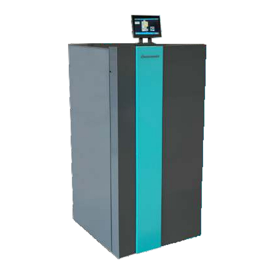
Status of delivery, additional equipment STATUS OF DELIVERY Equipment is delivered seperately: Boiler ZVB II (covered with casing with thermal insulation) on wood pallet with inbuilt and pre-wired: - color touch screen display (7") of boiler control unit (supplied in the boiler ash box) - NTC 5K - PVC l=2000 (26226) - Boiler temperature sensor - PT 1000 - Teflon l=1700 (62330) - Flue gas temperature sensor Additional parts and sensors in basic delivery:(supplied in the boiler ash box):... -
Page 4: Operating Environment
Operating environment This instruction booklet is an integral part of the product: make sure that it always accompanies the appliance, even in case of transfer to another owner or in the case of transfer to another place. In the event of damage or loss, request a copy from the area technician. - Page 5 Operating environment Flue pipes The flue pipe must have internal dimensions not larger than 20x20 cm, or diameter 20 cm. In the event of larger dimensions, or of the flue pipe being in poor condition (for example cracks, poor insulation, etc.), it is advisable to fit a stainless steel pipe of suitable diameter inside the flue pipe throughout its length, right up to the top.
- Page 6 Operating environment Chimney top: The top of the chimney must have the following conditions: • It must have the same diameter and internal shape of the chimney. • It must have a useful outlet diameter not less than twice the diameter of the flue pipe. •...
- Page 7 Operating environment Positioning 40 cm 20 cm The stove is equipped with an electric cable for connecting to a 230V, 50 Hz socket, preferably with a thermal-magnetic switch. Variations in voltage greater than 10% can endanger the operation of the furnace (if not already present, a suitable 40 cm 40 cm differential switch must be provided).
-
Page 8: Technical Specification
Technical specification Technical specification of ZVB II 16 3/4" 3/4" Φ50 Φ80 Ø80¹ - Smoke outlet tube Ø80 Ø50² - Diameter air intake Ø50 3/4"³ - Main flow 3/4" 3/4"⁴ - Return flow 3/4" - all dimensions are in mm - pictures and dimensions are approximate, tolerance may 10 mm Model... - Page 9 Technical specification Technical specification of ZVB II 20 3/4" 3/4" Φ80 Φ50 Ø80¹ - Smoke outlet tube Ø80 Ø50² - Diameter air intake Ø50 3/4"³ - Main flow 3/4" 3/4"⁴ - Return flow 3/4" - all dimensions are in mm - pictures and dimensions are approximate, tolerance may 10 mm Model...
- Page 10 Technical specification Technical specification of ZVB II 24 3/4" 3/4" Φ80 Φ50 Ø80¹ - Smoke outlet tube Ø80 Ø50² - Diameter air intake Ø50 3/4"³ - Main flow 3/4" 3/4"⁴ - Return flow 3/4" - all dimensions are in mm - pictures and dimensions are approximate, tolerance may 10 mm Model...
- Page 11 Technical specification Technical specification of ZVB II 32 3/4" 3/4" Φ100 Φ60 Ø100¹ - Smoke outlet tube Ø100 Ø60² - Diameter air intake Ø60 3/4"³ - Main flow 3/4" 3/4"⁴ - Return flow 3/4" - all dimensions are in mm - pictures and dimensions are approximate, tolerance may 10 mm Model...
-
Page 12: Safety Devices
Safety devices SAFETY DEVICES 1. Pressure switch: It controls the pressure in the smoke duct. It blocks the pellet transporter in case the drain is blocked or there are significant counter pressions, for example in the presence of wind, open combustion chamber door or fume extractor failure. 2. -
Page 13: Operating The System
Operating the system OPERATING THE SYSTEM If the installation of the boiler provides interaction with another existing system complete with a heater (gas boiler, gas boiler, oil boiler, etc..) consult qualifi ed personnel who can then answer the compliance of the system, as envisaged by the law in force. -
Page 14: Flushing The System
Operating the system Flushing the system: Recommendation: Before connecting the boiler to the heating system, it is recommended to flush the system to remove impurities and small residual particles during connection and installation. Connect the boiler to the heating system with removable sealed connections. When connecting the boiler, make one part between the boiler and the installation with flexible pipes, which will enable easier maintenance and, if necessary, moving the boiler. - Page 15 Configuration EXAMPLE OF SENSORS AND PUMPS CONNECTIONS (CONFIGURATION 1) PUMPS CSK1 1.P 2.G 3.T Outdoor Pellet level sensor (Additional equipment) 1 - Boiler ZVB II 4 - Room corrector CSK 1 ((K1) heating circuit 1) / 2 - P1 - (Boiler pump) CSK-Touch / Room thermostat 3 - (K1) Heating circuit 1 - (direct circuit) 5 - Outdoor temperature sensor...
- Page 16 Configuration CONFIGURATION / SCHEME CONFIGURATION 1 PUMPS CSK1 1.P 2.G 3.T Outdoor 1 - Boiler ZVB II 4 - Room corrector CSK 1 ((K1) heating circuit 1) / 2 - P1 - (Boiler pump) CSK-Touch / Room thermostat 3 - (K1) Heating circuit 1 - (direct circuit) 5 - Outdoor temperature sensor Notes: - in this configuration, it is not possible to connect the "CM2K module for regulation 2 heating circuits".
- Page 17 Configuration CONFIGURATION 3 PUMPS PUMPS Circuit 2 PUMPS CSK1 1.P 2.G 3.T Outdoor 1 - Boiler ZVB II 6 - P3 - Recirculation DHW (Heating circuit 2 (K2)) 2 - P1 - (Boiler pump) 7 - (K1) Heating circuit 1 - (direct circuit) 3 - P2 - Diverting valve 8 - Room corrector CSK 1 ((K1) heating circuit 1) / 4 - (K2) Heating circuit 2 (DHW)
- Page 18 Configuration CONFIGURATION 5 PUMPS MIX VALVE CL1 OP1 Return Buffer up Buffer down PUMPS Outdoor CSK-Touch CSKT 1 - Boiler ZVB II 6 - Temperature sensor (UP) - accumulation (buffer) tank - (Boiler pump) 7 - Temperature sensor (DOWN) - accumulation (buffer) tank 3 - MIXING VALVE (3-way mixing valve with actuator) - Recirculation DHW 4 - Temperature sensor (boiler circuit - return flow)
- Page 19 Configuration CONFIGURATION 7 PUMPS Buffer up Buffer down PUMPS Outdoor CSK-Touch CSKT 1 - Boiler ZVB II 5 - Temperature sensor (UP) - accumulation (buffer) tank 2 - P1 - (Boiler pump) 6 - Temperature sensor (DOWN) - accumulation (buffer) tank 3 - Return flow protection (3-way thermostatic valve) 7 - P2 - Recirculation DHW 4 - "CAS-B"...
- Page 20 Configuration CONFIGURATION 9 PUMPS Buffer up Buffer down MIX VALVE CL1 OP1 PUMPS Circuit 1 PUMPS CSK1 1.P 2.G 3.T Outdoor 1 - Boiler ZVB II 8 - P2 - (Heating circuit 1 (K1)) 2 - P1 - (Boiler pump) 9 - Temperature sensor ((K1) Heating circuit 1 - main flow) 3 - Return flow protection (3-way thermostatic valve) 10 - P3 - Recirculation DHW...
- Page 21 Configuration CONFIGURATION 11 PUMPS Buffer up Buffer down PUMPS Circuit 1 PUMPS Outdoor CSK-Touch CSKT 1 - Boiler ZVB II 7 - P2 - DHW (Heating circuit 1 (K1)) 2 - P1 - (Boiler pump) 8 - (K1) Heating circuit 1 (DHW) 3 - Return flow protection (3-way thermostatic valve) 9 - Temperature sensor DHW ((K1) Heating circuit 1) 4 - "CAS"...
- Page 22 Configuration CONFIGURATION 13 PUMPS MIX VALVE CL1 OP1 Return PUMPS Circuit 1 Buffer up Buffer down PUMPS 1 - Boiler ZVB II Temperature sensor DHW ((K1) Heating circuit 1) Outdoor - (Boiler pump) 8 - "CAS" accumulation (buffer) tank CSK-Touch 3 - MIXING VALVE (3-way mixing valve with actuator) 9 - Temperature sensor (UP) - accumulation (buffer) tank CSKT...
- Page 23 Configuration CONFIGURATION 15 PUMPS PUMPS Circuit 2 Buffer up Buffer down MIX VALVE CL1 OP1 PUMPS Circuit 1 CSK1 1.P 2.G 3.T 1 - Boiler ZVB II 10 - MIXING VALVE 1 (3-way mixing valve with actuator - - (Boiler pump) heating circuit 1 (K1)) 3 - Return flow protection (3-way thermostatic valve) Outdoor...
- Page 24 Configuration CONFIGURATION 17 PUMPS PUMPS PUMPS Circuit 1 Buffer up Buffer down Outdoor CSK-Touch CSKT 1 - Boiler ZVB II 7 - Temperature sensor DHW ((K1) Heating circuit 1) 2 - P1 - (Boiler pump) 8 - "CAS" accumulation (buffer) tank 3 - Return flow protection (3-way thermostatic valve) 9 - Temperature sensor (UP) - accumulation (buffer) tank 4 - P2 - BUF (accumulation (buffer) tank)
- Page 25 Configuration CONFIGURATION 19 PUMPS Outdoor CSK-Touch CSKT 1 - Boiler ZVB II 4 - Hydraulic crossover 2 - P1 - (Boiler pump) 5 - Outdoor temperature sensor 3 - Return flow protection (3-way thermostatic valve) Notes: - in this configuration is possible to connect up to 3 unit "CM2K module for regulation 2 heating circuits“. * in this configuration is possible to connect CSK-Touch (additional equipment) only if CM2K is installed.
- Page 26 Configuration CONFIGURATION 21 PUMPS MIX VALVE CL1 OP1 Return PUMPS Circuit 1 PUMPS Outdoor CSK-Touch CSKT 1 - Boiler ZVB II 6 P2 - DHW (Heating circuit 1 (K1)) - (Boiler pump) 7 - (K1) Heating circuit 1 (DHW) 3 - MIXING VALVE (3-way mixing valve with actuator) 8 - Temperature sensor DHW ((K1) Heating circuit 1) 4 - Temperature sensor (boiler circuit - return flow) 9 - P3 - Recirculation DHW (Heating circuit 1 (K1))
- Page 27 Configuration CONFIGURATION 23 PUMPS MIX VALVE CL1 OP1 PUMPS Circuit 1 PUMPS Circuit 2 CSK1 1.P 2.G 3.T Outdoor 1 - Boiler ZVB II 7 - P3 - DHW (Heating circuit 1 (K1)) - (Boiler pump) 8 - (K2) Heating circuit 2 (DHW) 3 - Return flow protection (3-way thermostatic valve) 9 - Temperature sensor DHW ((K2) Heating circuit 2) 4 - MIXING VALVE 1 (3-way mixing valve with actuator -...
-
Page 28: Electrical Wiring
Electrical wiring ELECTRICAL WIRING Back view 1 - CABLE GROMMETS - Devices (230 V) 2 - CABLE GROMMETS - Low-voltage or no-voltage conductors 3 - CABLE GROMMET - UTP cable (connection of additional equipment) 4 - Safety thermostat (STB) 5 - Main switch (0/1) 6 - Connector for connection cable 230 V All input/output cables (230 V and low voltage) must be fastened in the "Place for fastening of cables". - Page 29 Holder and boiler control unit screen installation HOLDER AND BOILER CONTROL UNIT SCREEN INSTALLATION screen holder Rubber grommet 1. The place where the holder with the screen should be mounted. 2. It is necessary to unscrew the two screws (2a) which hold the metal plate and the UTP cable (2b). 3.
- Page 30 Fuses FUSES Main PCB: UniDrive Mark: F2 3,15 A, F Mark: F1 3,15 A, F DEVICES MARK FUSE - Pumps P1, P2, P3, P4 (total max. = 3 A) 3,15 A, F - UniDrive PCB power supply - Electric heater - Flue gas fan (with RPM sensor) 3,15 A, F - Mixing valve...
-
Page 31: Electrical Scheme
Electrical scheme ELECTRICAL SCHEME All electrical connections must be made according to this electrical scheme. Technical instructions ZVB II... - Page 32 Electrical scheme Technical instructions ZVB II...
- Page 33 Electrical scheme Technical instructions ZVB II...
- Page 34 Electrical scheme Technical instructions ZVB II...
- Page 35 Electrical scheme Technical instructions ZVB II...
- Page 36 Electrical scheme Technical instructions ZVB II...
- Page 37 Electrical scheme Technical instructions ZVB II...
- Page 38 Electrical scheme Technical instructions ZVB II...
-
Page 39: Cleaning And Maintenance
Cleaning and maintenance CLEANING AND MAINTENANCE When turning off the boiler, never just pull the plug from the power supply, but let the boiler go through the shutdown phase on its own, otherwise problems may arise during the next start-up. Maintenance and cleaning of the grate and boiler without automatic grate cleaning and automatic ash removal: Important! All cleaning of all parts must be carried out with the Boiler completely cold and unplugged to avoid burns and thermal shock. - Page 40 Cleaning and maintenance Clean the grate using the appropriate tool from the ash and any incrustation which could obstruct the passage of air. In the case of depletion of pellets in the tank may accumulate unburned pellets in the burn pot. Always empty the residuals from the grate before each start.
- Page 41 Cleaning and maintenance Check every 60-90 days Lower ash drawer cleaning Check every 7 days Inside the compartment where there is the ash tray, there is a second cover, fixed by the cockerels, which gives access to the Clean bottom ash from the fallen debris during operation. compartment at the base of the duct dedicated to the flue and You can access the ash pan by loosening the two wing the wall of the fume extractor fan.
- Page 42 Cleaning and maintenance Control of electrical and mechanical parts is carried out by an authorized service. It is recommended to check the following parts at least once a year: • reduction motor • flue gas expulsion fan • flue gas sensor •...
- Page 43 Cleaning and maintenance When turning off the boiler, never just pull the plug from the power supply, but let the boiler go through the shutdown phase on its own, otherwise problems may arise during the next start-up. Maintenance and cleaning of the gate and boiler with automatic grate cleaning and without automatic ash removal: Important! All cleaning of all parts must be carried out with the Boiler completely cold and unplugged to avoid burns and thermal shock.
- Page 44 Cleaning and maintenance Clean the grate using the appropriate tool from the ash and any incrustation which could obstruct the passage of air. In the case of depletion of pellets in the tank may accumulate unburned pellets in the burn pot. Always empty the residuals from the grate before each start.
- Page 45 Cleaning and maintenance When the boiler is not used for a long time When we do not use the boiler for a long time, it must be disconnected from the electricity supply. To be completely safe, it is recommended to remove the power cable (for the safety of the children, etc.) When the boiler is not going to be used for a long time, it is recommended to remove all the pellets from the tank because it can collect moisture, and when we want to start it again, there may be difficulties during ignition and irregularities in operation.
- Page 46 Changing the boiler control unit screen battery (CR 1632) CHANGING THE BOILER CONTROL UNIT SCREEN BATTERY (CR 1632) If there is a significant clock delay or the clock settings are automatically set to 00:00 and the date to 1.1.2020. (after turning OFF/ON the main switch of the boiler or after a power failure) it is necessary to replace the battery located on the bottom side of the screen (battery type CR 1632).
-
Page 47: Correct Disposal Of This Product
Correct disposal of this product CORRECT DISPOSAL OF THIS PRODUCT Your boiler is marked in accordance with Directives: 2006/42/EC, 2014/30/EU, 2014/35/EU and contains electrical components. According to EU Regulation 2015/1189 implementing Directive 2009/125/EC with regard to Eco- Design requirements for solid fuel boilers, we draw your attention to the following: MARK FOR MARKING SEPARATE EE WASTE COLLECTION This marking on the product indicates that the product contains electrical and electronic parts and must be disposed of separately, it must not be mixed with other waste. - Page 48 Company assumes no responsibility for possible inaccuracies in this book originated typographical errors or rewriting, all the pictures and diagrams are principal and it is necessary to adjust each actual situation on the field, in any case the company reserves the right to enter their own products such modifications as considered necessary. Centrometal d.o.o. Glavna 12, 40306 Macinec, Croatia www.centrometal.hr central tel: +385 40 372 600, fax: +385 40 372 611 e-mail: servis@centrometal.hr...
Need help?
Do you have a question about the ZVB II 16-32 and is the answer not in the manual?
Questions and answers