Table of Contents
Advertisement
Quick Links
Advertisement
Table of Contents

Subscribe to Our Youtube Channel
Related Manuals for Centrometal EKO-CUP SV3 2500


Summary of Contents for Centrometal EKO-CUP SV3 2500
- Page 1 HEATING TECHNIQUE Centrometal d.o.o. - Glavna 12, 40306 Macinec, Croatia, tel: +385 40 372 600, fax: +385 40 372 611 TECHNICAL INSTRUCTIONS for installation, use and maintenance of the hot water boiler and installation of the additional equipment EKO-CUP SV3 2500...
- Page 2 Please note that the installation, startup and maintenance can only be performed by a qualified heating contractor or service organization. Any work on electrical installations and fuel carrying components must be done by a qualified service technician. Technical instructions EKO-CUP SV3 2500...
- Page 3 Keep the boiler room door closed. Protect the boiler room and avoid rodents and birds from entering and blocking the air openings. If the above mentined issues are not solved, the boiler cannot be put into operation. Technical instructions EKO-CUP SV3 2500...
-
Page 4: Technical Data
(PSB) (kW) 0.006 Flame operation direct flame operation multi stage Boiler type (Weishaupt WM-GL30-2-ZM-T) DESCRIPTION: values given in the table are test report values issued by SZU s.p., Brno, Czech Republic. GAS/OIL: burner Weishaupt WM-GL30-2-ZM-T Technical instructions EKO-CUP SV3 2500... - Page 5 4 Filling / drainage R” 5 Sensors / gauges R” 6 Min / Max pressure limit switch R” 7 Position for probe - R” exhaust gases emissions Boiler resistance on water side Flow in m /h Technical instructions EKO-CUP SV3 2500...
- Page 6 Boiler EKO-CUP SV3 2500 component parts 2.0. BOILER EKO-CUP SV3 2500 COMPONENT PARTS Position for Min/Max Control Boiler Safety Sensors/ Sensor Main Flue Boiler Boiler door panel outter line Gauges tube flow probe - pressure return with panneling exhaust outlet...
-
Page 7: Boiler Description
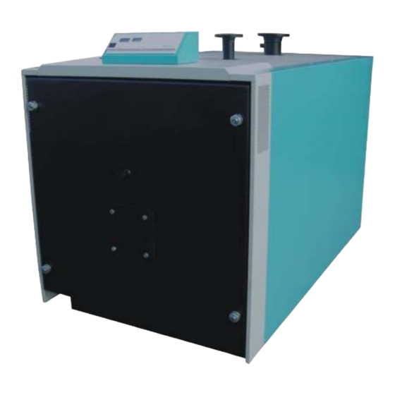
BOILER DESCRIPTION The boiler EKO-CUP SV3 2500 is a triple pass flue gas flow system steel hot water boiler. Flue gases flow from the combustion chamber into the tube of second pass and then into the tube of third pass, where turbulators are placed. - Page 8 Insulation mounting Figure 1: The boiler outer panelling assembly EKO-CUP SV3 2500 M8x15 M8x35 4,2x30 bracket-X PROCES OF PANELLING ASSEMBLY ON THE BOILER: 1. Put side panels onto bracket-X in the order shown on the figure – panels 1 to 12 (panels 1 to 6 are the same and panels 7 to 12 are the same).
-
Page 9: Connection To The Chimney
1m between the boiler and the chimney or wall. Figure 2: Possible way to connect the Figure 3: Possible way to connect the EKO-CUP SV3 2500 boiler to the chimney EKO-CUP SV3 2500 boiler to the chimney Opening for cleaning 10 mm min. 1 m min. - Page 10 3-way mixing valve with motor actuator, that will keep temperature above 60°C. Depending on configuration or controller, this motor actuator may have its own controller or it can be controlled by a boiler controller. Technical instructions EKO-CUP SV3 2500...
-
Page 11: Water Quality
To prevent excessive limescale build-up of calcium carbonate on the boiler heating surfaces, its concentration must be below the permitted maximum values mentioned in the following table: Boiler Total alkaline earths mol/m³ Total hardness °dH EKO-CUP SV3 2500 < 0.02 < 0.11 Technical instructions EKO-CUP SV3 2500... - Page 12 If there are still frequent interruptions during the boiler operation, it is necessary to contact the qualified person to check it out. 7. THERMOMETER The thermometer indicates the boiler water temperature in °C. 8. POSITION FOR MOUNTING HEATING CONTROL UNIT (additional equipment) Technical instructions EKO-CUP SV3 2500...
- Page 13 Control panel Boiler EKO-CUP SV3 2500 The first burner stage thermostat sensor The second burner stage thermostat sensor The safety boiler thermostat (STB) sensor The thermometer sensor (put the sensors into the sensors tube) sensors tube Technical instructions EKO-CUP SV3 2500...
- Page 14 10.2. CONNECTION TO THE ELECTRIC INSTALLATION The boiler EKO-CUP SV3 2500 is equipped with a boiler control panel. During the installation of electrical installations, which must be done by a qualified person it is first necessary to take off the lid on the back side of the basic boiler controller (Figure 4), on which line clamps for the electric supply, burner connection and circulation pumps are positioned.
-
Page 15: Burner Selection
(which is delivered with the boiler). DIMENSIONS (mm) - WM-GL30/2 ZM-T flange connection fresh air supply intake in accordance with DIN EN 1092-1 1146 349 – 374 Technical instructions EKO-CUP SV3 2500... -
Page 16: Boiler Startup
Burner mounting, boiler startup Figure 5: Burner mounting on the boiler EKO-CUP SV3 2500 Mineral wool Insulation panel Gap which must Blind panel be closed Burner tube Boiler door insulation 12.0. BOILER STARTUP Before startup please check if: - the flue gas tube is properly sealed and the boiler is connected to the power supply... -
Page 17: Boiler Use
- See item „BOILER CONTROL PANEL“, use the MAIN SWITCH and the REGULATION THERMOSTAT FOR THE FIRST BURNER STAGE to start the boiler. Use the REGULATION THERMOSTAT FOR THE SECOND BURNER STAGE for boiler regulation temperature. Technical instructions EKO-CUP SV3 2500... -
Page 18: Cleaning And Maintenance Schedule
Heating system check. Before boiler use operation, position and function of important components in the system. Air-vent the heating system and fill it with water if is necessary. Technical instructions EKO-CUP SV3 2500... - Page 19 Notes Technical instructions EKO-CUP SV3 2500...
- Page 20 Centrometal d.o.o. shall not be responsible for possible incorrect data caused by printing errors or error made in transcription and all figures and diagrams are for explanatory purposes only and relevant adjustment have to be made at the spot. In any case, it reserves the right to modify its products as deemed to be required and useful without any prior notification.
Need help?
Do you have a question about the EKO-CUP SV3 2500 and is the answer not in the manual?
Questions and answers