Table of Contents

Related Manuals for Centrometal El-Cm Compact 9


Summary of Contents for Centrometal El-Cm Compact 9
- Page 1 HEATING TECHNIQUE Centrometal d.o.o. - Glavna 12, 40306 Macinec, CROATIA, tel: +385 40 372 600, fax: +385 40 372 611 TECHNICAL MANUAL for assembling, use and maintenance of the electric boiler and additional equipment El-Cm Compact TUELCMC-03/2010-eng...
-
Page 2: Technical Data
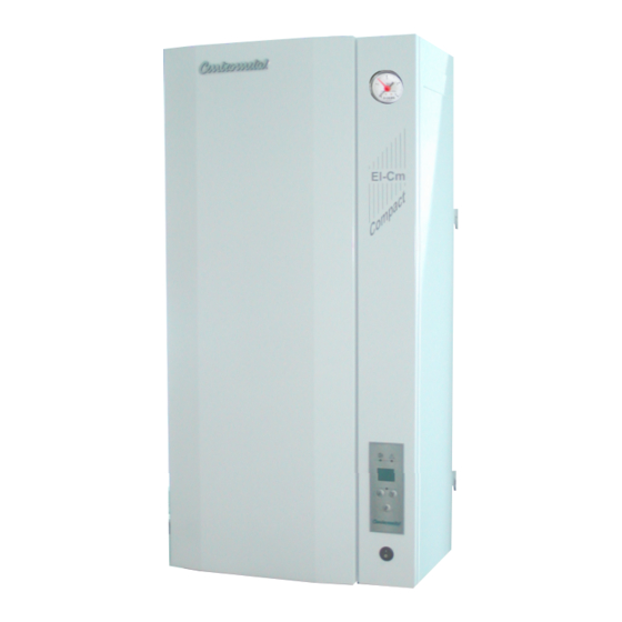
Technical data Picture 1. - Basic technical dimensions of the electrical boiler El-Cm Compact Manometar El-Cm Console of the regulation Front cover Digital modulating regulation TEHNIKA GRIJANJA Main switch TECHNICAL DATA El-Cm Compact (kW) Nom.thermal output (lit.) Capacity (kg) Electric boiler mass (bar) Max. - Page 3 Essential parts Picture 2. - Essential parts of the electric boiler El-Cm Compact Inlet Outlet Wire introducer (room thermostat) Wire introducer (power supply) Regulation box Microswitch Sensor probe 1 2 3 Pressure switch Boiler Safety thermostat Electric heater Expansion vessel Circulation pump Boiler porter Thermal insulation...
-
Page 4: Boiler Description
Boiler description 1.0. INTRODUCTION Hot water electric boiler El-Cm Compact has a modern design and is constructed out of certified high quality materials by applying most modern robot welding technology, it is certified according to domestic and international norms and is therefore suitable for connection to central heating system installation. -
Page 5: Boiler Parts
Boiler parts OUTLET The outlet tube (1”) is marked by the blue coloured sticker and is placed on the upper left side of the electric boiler. It is inserted through the whole length of the electric boiler till its deepest point in order to spread the cooled water inside the electric boilers body and over the electric heater/heaters. - Page 6 Installation of electric boiler 4.0. INSTALLATION OF ELECTRIC BOILER The El-Cm Compact electric boiler is aimed to be hanged on the wall. For the easier setting on the wall, there is a hanging console on its back part which is to be hanged on wall metal dowels of M10 type or even stronger.
- Page 7 Connecting to the central heating system 5.0. CONNECTING THE El-Cm Compact TO THE CENTRAL HEATING SYSTEM Connecting to tube installation of the central heating system and the start-up of the electric boiler has to be executed considering all technical standards and norms, on behalf of the authorized person, who is able to take over the responsibility.
-
Page 8: Electric Connection
Electric connection 6.0. CONNECTION TO THE ELECTRICAL POWER NET All connections to the electrical power net have to be executed in compliance with all norms and standards by an authorized person. The electric boiler is completely prewired. All additional connections (electric boiler supply, room thermostat) are aimed to be connected through the ordinaly terminal on the upper left side of the device, under the front cover of the electric boiler. -
Page 9: Electric Scheme
Electric scheme Scheme 1. - Electric scheme of the El-Cm Compact 6-12 kW (3-phase connection) REGULATION PANEL Connection voltage 3x400V Pump Ordinaly terminal EG EG EG EG EG EG LEGEND: P - main switch K - contactor 1 LED-DISPLAY ST - safety thermostat EG - electric-heater K - contactor RE - electronic of regulation... - Page 10 Electric scheme Scheme 2. - Electric scheme of the El-Cm Compact 15-18 kW (3-phase connection) REGULATION PANEL Connection voltage 3x400V Pump Ordinaly terminal EG EG EG EG EG EG EG EG EG P - main switch K - contactor 1 LEGEND: LED-DISPLAY ST - safety thermostat...
- Page 11 Electric scheme Scheme 3. - Electric scheme of the El-Cm Compact 21-27 kW (3-phase connection) REGULATION PANEL Connection voltage 3x400V Pump Ordinaly terminal EG EG EG EG EG EG EG EG EG EG EG LEGEND: P - main switch K - contactor 1 LED-DISPLAY ST - safety thermostat EG - electric-heater...
- Page 12 Replacement of the el. heaters 7.0. TECHNICAL DATA - tension:.....................400V / 50Hz - el. boiler steering mode:.............modulating regulation - electronic part consumption:...............max. 10 VA - regulation area:..................20-85°C 8.0. REPLACEMENT OF THE ELECTRIC HEATER Before You take off the front cover it is necessary to disconnect the power supply. Then we take off the front cover and lower side of the casing (which are fasten with the screws).
- Page 13 Regulation 9.0. REGULATION The regulator of the El-Cm Compact measures the Picture 5. - Digital regulation temperature and compares it with the set up (desired) temperature. On this basis it searches for the optimal Error (LED-diode) apportionment of the power used for the system heating to the desired temperature.
- Page 14 Table of resistance of the boiler sensor TABLE OF RESISTANCE OF THE NTC 5k/25°C BOILER SENSOR (measuring field from - 20 to + 130 °C) Temperature (°C) Resistance (Ω) 48.535 36.465 27.665 21.158 16.325 12.694 9.950 7.854 6.245 5.000 4.028 3.266 2.663 2.184...
- Page 15 Errors Example: El-Cm Compact 12kW Always after the start-up the electric boiler is warming up intensively, until the desired temperature level has been reached. When the desired temperature level has been reached, the regulator steers the operation of the electric boiler allocating the power of activated heaters depending to the desired temperature to be reached, step by step, i.e.
- Page 16 Centrometal d.o.o. Glavna 12, 40306 Macinec, CROATIA central tel: +385 40 372 600, fax: +385 40 372 611 service tel: +385 40 372 622, fax: +385 40 372 621 www.centrometal.hr e-mail: servis@centrometal.hr HEATING TECHNIQUE...
Need help?
Do you have a question about the El-Cm Compact 9 and is the answer not in the manual?
Questions and answers