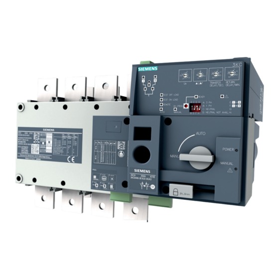
Siemens SENTRON Manual

Transfer switching equipment and load transfer switches
Hide thumbs Also See for SENTRON:
Table of Contents

Advertisement

Advertisement

Table of Contents
loading

Summary of Contents for Siemens SENTRON

  • Page 3 ___________________ Introduction ___________________ General information ___________________ Product information ___________________ Functions ___________________ Mounting ___________________ Connection Manual ___________________ Operation ___________________ Commissioning ___________________ Accessories ___________________ Service and maintenance ___________________ Technical specifications ___________________ Dimension drawings ___________________ Applications ___________________ Appendix ___________________ ESD guidelines ___________________ List of abbreviations 08/2017 L1V30368969104A-02...
  • Page 4: Legal Information

    Note the following: WARNING Siemens products may only be used for the applications described in the catalog and in the relevant technical documentation. If products and components from other manufacturers are used, these must be recommended or approved by Siemens. Proper transport, storage, installation, assembly, commissioning, operation and maintenance are required to ensure that the products operate safely and without any problems.
  • Page 5: Table Of Contents

    Table of contents Introduction ............................. 9 General information ..........................11 Certification ..........................11 Product information ..........................13 Product description ......................... 13 3.1.1 Design of the 3KC4 and 3KC8 transfer switching equipment..........14 3.1.2 Current ratings of the 3KC4 and 3KC8 transfer switching equipment ........18 Product family .........................
  • Page 6 Table of contents Connecting the main circuit ....................39 6.2.1 Connecting terminals of the transfer switching equipment ............ 39 6.2.2 Load connection ........................40 6.2.3 Arrangement of the power supply systems ................40 6.2.4 Connection of transfer switching equipment for current ratings 250 A to 1600 A ....42 6.2.4.1 Connecting bridging bars on the load side ................
  • Page 7 Table of contents Automatic mode - programming of the electronic module (3KC8 only) ........ 132 7.4.1 Step 1: Preset network conditions ..................132 7.4.2 Step 2: Setting the potentiometer ..................134 7.4.3 Step 3: Automatic configuration of the transfer switching equipment (only with potentiometer Un = 0) ......................
  • Page 8 Table of contents Technical specifications ........................183 11.1 Technical specifications 3KC4 and 3KC8 from 250 A to 1000 A ......... 183 11.2 Technical specifications 3KC4 and 3KC8 from 1250 A to 3200 A ........186 11.3 Technical specifications of the electronic module ..............189 Dimension drawings ..........................
  • Page 9: Introduction

    A general knowledge of low-voltage power distribution is required to understand this manual. Technical support You can find further support on the Internet at: Technical support (https://www.siemens.com/lowvoltage/technical-support) Applicable documents You can find more information on the Internet via the following link: Manual "3KC Transfer Switching Equipment up to 3200 A"...
  • Page 10 Introduction Manual, 08/2017, L1V30368969104A-02...
  • Page 11: General Information

    General information The transfer switching equipment and its accessories comply with the following international standards: Standard Designation IEC 60269-1 Low-voltage fuses - Part 1: General requirements IEC 60269-2 Low-voltage fuses - Part 2: Supplementary requirements for fuses for use by qualified electrical technicians or electrically trained persons (fuses pre- dominantly for industrial use) IEC 60947-1 Low-voltage switchgear and controlgear - Part 1: General requirements...
  • Page 12 General information 2.1 Certification Manual, 08/2017, L1V30368969104A-02...
  • Page 13: Product Information

    Product information Product description The following features of the 3KC4 and 3KC8 transfer switching equipment are described in this chapter: ● Design ● Current ratings Manual, 08/2017, L1V30368969104A-02...
  • Page 14: Design Of The 3Kc4 And 3Kc8 Transfer Switching Equipment

    Product information 3.1 Product description 3.1.1 Design of the 3KC4 and 3KC8 transfer switching equipment 3KC4 remotely operated transfer switching equipment (RTSE): Manual, 08/2017, L1V30368969104A-02...
  • Page 15 Product information 3.1 Product description 3KC8 automatic transfer switching equipment (ATSE): ① ⑪ Switching unit Switch for selecting the mode (Manual / ② Automatic) Connecting terminal of the main source ⑫ (source I) Padlock assembly ③ ⑬ Connecting terminal of the alternative source 4 outputs for (source II) "Switch position"...
  • Page 16 Product information 3.1 Product description The 3KC8 automatic transfer switching equipment (ATSE) is based on the 3KC4 (RTSE) transfer switching equipment. In contrast to the 3KC4, an electronic module is additionally integrated into the 3KC8. The electronic module enables monitoring of 2 sources as well as automatic transfer switching.
  • Page 17 Product information 3.1 Product description Indicators (LEDs) Designation Function Meaning ① Availability Shows a continuous green light if source I is available source I and is within the accepted tolerance. ② Availability Shows a continuous green light if source II is available source II and is within the accepted tolerance.
  • Page 18: Current Ratings Of The 3Kc4 And 3Kc8 Transfer Switching Equipment

    Product information 3.1 Product description ⑨ TEST "Test off load" Shows a continuous yellow light if the transfer switching OFF LOAD mode equipment is in "Test off load" mode. ⑩ Position II indication Shows a continuous green light if the switch is in posi- tion II.
  • Page 19 Product information 3.1 Product description Designs The following figures show the different designs of the transfer switching equipment depicted according to current rating using the example of the 3KC8 transfer switching equipment: 3KC8 250 A 3KC8 400 A 3KC8 630 A 3KC8 800 A / 1000 A 3KC8 1250 A 3KC8 1600 A...
  • Page 20 Product information 3.1 Product description 3KC8 2000 A / 2500 A / 3200 A Manual, 08/2017, L1V30368969104A-02...
  • Page 21: Product Family

    3.2 Product family Product family 3.2.1 The product families 3KC4 and 3KC8 from 250 A to 3200 A The Siemens product families 3KC4 and 3KC8 from 250 A to 3200 A encompass two types of transfer switching equipment: Product Type...
  • Page 22: Use Of 3Kc4 And 3Kc8 Transfer Switching Equipment

    Product information 3.2 Product family 3.2.2 Use of 3KC4 and 3KC8 transfer switching equipment The 3KC4 and 3KC8 transfer switching equipment is used to ensure a continuous supply of power. The equipment enables reliable transfer between a main source and an alternative source, thus a power supply is provided by means of an emergency source if the main source is not available.
  • Page 23: Application Areas Of The 3Kc4 And 3Kc8 Transfer Switching Equipment

    Product information 3.2 Product family 3.2.4 Application areas of the 3KC4 and 3KC8 transfer switching equipment The 3KC4 and 3KC8 transfer switching equipment can be used in all areas where a continuous power supply must be ensured. Service sector ● Public facilities ●...
  • Page 24 Product information 3.2 Product family Manual, 08/2017, L1V30368969104A-02...
  • Page 25: Functions

    Functions The 3KC4 and 3KC8 transfer switching equipment offers the following functions for maintaining a power supply: Function 3KC4 3KC8 Remotely operated transfer switching (RTSE) ✓ Automatic transfer switching (ATSE) ✓ Power supply via 2 inputs (internal dual power supply) ✓...
  • Page 26 Functions Manual, 08/2017, L1V30368969104A-02...
  • Page 27: Mounting

    Mounting The following content is described in this chapter: ● Mounting positions for the 3KC4 and 3KC8 transfer switching equipment ● Installation of the 3KC4 and 3KC8 transfer switching equipment Mounting position Current rating Mounting position Motor operator Motor operator Motor operator Motor operator right...
  • Page 28 Mounting 5.2 Installing the 3KC4 and 3KC8 transfer switching equipment Installing the current ratings 250 A to 630 A Figure 5-1 Installing the current ratings 250 A to 630 A The dimensions vary according to the current rating and the number of poles. They can be found in the table below.
  • Page 29 Mounting 5.2 Installing the 3KC4 and 3KC8 transfer switching equipment Installing the current ratings 800 A to 3200 A Proceed as follows to install the 3KC4 and 3KC8 transfer switching equipment of current ratings 800 A to 3200 A: Figure 5-2 Installing the current ratings 800 A to 3200 A The dimensions vary according to the current rating and the number of poles.
  • Page 30: Dimensions Of The Cover Frame For Door Cut-Out

    Mounting 5.3 Dimensions of the cover frame for door cut-out Dimensions of the cover frame for door cut-out The following figures show the dimensions of the cover frame for door cut-out for the 3KC4 and 3KC8 transfer switching equipment. Note On the 3KC8 transfer switching equipment there is an additional electronic module that enables source monitoring.
  • Page 31: Connection

    Connection The following content is described in this chapter: ● Network types ● Connection to the source (connecting terminals, connection instructions for each current rating, required accessories) ● Inputs and outputs of the motor operator and accessories ● Inputs and outputs of the electronic module ●...
  • Page 32: Three-Phase 4-Wire Network With Neutral (3Ph + N)

    Connection 6.1 Network types 6.1.1 Three-phase 4-wire network with neutral (3PH + N) The 3KC4 and 3KC8 transfer switching equipment can be used in a network comprising three phases and a neutral conductor. 6.1.1.1 Circuit diagram for the 3KC4 transfer switching equipment - 4-pole transfer switching equipment Figure 6-1 Three-phase 4-wire network with neutral for the 3KC4 transfer switching equipment...
  • Page 33: Circuit Diagram For The 3Kc8 Transfer Switching Equipment - 4-Pole Transfer Switching Equipment

    Connection 6.1 Network types 6.1.1.2 Circuit diagram for the 3KC8 transfer switching equipment - 4-pole transfer switching equipment Figure 6-2 Three-phase 4-wire network with neutral for the 3KC8 transfer switching equipment The power supply kit accessories 3KC9830-, 3KC9831- can be used for the power supply of the transfer switching equipment.
  • Page 34: Equipment

    Connection 6.1 Network types 6.1.2.1 Circuit diagram for the 3KC4 transfer switching equipment - 3-pole transfer switching equipment Figure 6-3 Three-phase 3-wire network without neutral for the 3KC4 transfer switching equipment 2 x 3NW6002-1 2 A, gG 1 x 3NW7023 1 x 3NW6004-1 4 A, gG 1 x 3NW7013...
  • Page 35: Circuit Diagram For The 3Kc8 Transfer Switching Equipment - 4-Pole Transfer Switching

    Connection 6.1 Network types 6.1.2.2 Circuit diagram for the 3KC8 transfer switching equipment - 4-pole transfer switching equipment Figure 6-4 Three-phase 3-wire network without neutral for the 3KC8 transfer switching equipment (4-pole) 2 x 3NW6002-1 2 A, gG 1 x 3NW7023 1 x 3NW6004-1 4 A, gG 1 x 3NW7013...
  • Page 36: Circuit Diagram For The 3Kc8 Transfer Switching Equipment - 3-Pole Transfer Switching Equipment

    Connection 6.1 Network types 6.1.2.3 Circuit diagram for the 3KC8 transfer switching equipment - 3-pole transfer switching equipment Figure 6-5 Three-phase 3-wire network without neutral for the 3KC8 transfer switching equipment (3-pole) 2 x 3NW6002-1 2 A, gG 1 x 3NW7023 1 x 3NW6004-1 4 A, gG 1 x 3NW7013...
  • Page 37: Single-Phase Network With Neutral (1Ph + N)

    Connection 6.1 Network types 6.1.3 Single-phase network with neutral (1PH + N) The 3KC4 and 3KC8 transfer switching equipment can be used in a single-phase network comprising one phase and a neutral conductor. Since there is no 2-pole design available for the transfer switching equipment, the 3KC4 and 3KC8 transfer switching equipment in 3-pole design is the best choice.
  • Page 38: Circuit Diagram For The 3Kc8 Transfer Switching Equipment - 3-Pole Transfer Switching

    Connection 6.1 Network types 6.1.3.2 Circuit diagram for the 3KC8 transfer switching equipment - 3-pole transfer switching equipment No fuse required if the power supply kit accessories 3KC9833-, 3KC9834- are used Figure 6-7 Single-phase system without 3KC8 transfer switching equipment 1 x 3NW6004-1 4 A, gG 1 x 3NW7013...
  • Page 39: Connecting The Main Circuit

    Connection 6.2 Connecting the main circuit Connecting the main circuit In the following chapter, you will find a description of the connection options for the 3KC4 and 3KC8 transfer switching equipment. 6.2.1 Connecting terminals of the transfer switching equipment The connecting terminals of the 3KC4 and 3KC8 transfer switching equipment differ depending on the current rating.
  • Page 40: Load Connection

    Connection 6.2 Connecting the main circuit 6.2.2 Load connection The following figure shows the two fundamentally possible arrangements for the connected load. It can be connected at the top or bottom. Figure 6-8 Arrangements for load connection 6.2.3 Arrangement of the power supply systems Since both the 3KC4 and the 3KC8 have a flat connector, they can be connected to the power supply system using cable lugs or busbars.
  • Page 41 Connection 6.2 Connecting the main circuit With network/network applications, any arrangement of the connection can be selected. With the 3KC8 transfer switching equipment, prioritization of the source can be implemented via the corresponding inputs. For information, see the section titled Functions of the control inputs for network / generator application (Page 119).
  • Page 42: Connection Of Transfer Switching Equipment For Current Ratings 250 A To 1600 A

    Connection 6.2 Connecting the main circuit 6.2.4 Connection of transfer switching equipment for current ratings 250 A to 1600 A The connection of current ratings 250 A to 1600 A to the main circuit is described in the following section. To connect the 3KC4 and 3KC8 transfer switching equipment properly, you must first mount the bridging bar accessories on the load side.
  • Page 43 Connection 6.2 Connecting the main circuit Requirements ● Power supply is switched off ● Transfer switching equipment is in the "Manual" position Procedure Figure 6-12 Mounting bridging bars for current ratings 250 A to 630 A Current rating 250 A M10 x 20 mm 20 ...
  • Page 44 Connection 6.2 Connecting the main circuit Mounting bridging bars for current ratings 800 A to 1600 A The following steps are necessary for mounting the bridging bars on the transfer switching equipment. Refer to the table for information about the bolts, tools, and tightening torques. The bolts for mounting the bridging bars are included in the scope of supply.
  • Page 45 Connection 6.2 Connecting the main circuit Current rating 800 A ... 1000 A M8 x 35 mm 8.3 ... 13 1250 A M10 x 40 mm 20 ... 26 1600 A M12 x 45 mm 40 ... 45 1. Position the bridging bar on the connecting terminal. 2.
  • Page 46: Connecting Current Ratings 250 A To 1600 A To The Main Circuit

    Connection 6.2 Connecting the main circuit 6.2.4.2 Connecting current ratings 250 A to 1600 A to the main circuit The following steps are necessary for connecting the transfer switching equipment to the main circuit. Refer to the respective table for information about the permissible copper connections, required tools, and tightening torques.
  • Page 47 Connection 6.2 Connecting the main circuit Current ratings 250 A to 630 A Requirements ● Main circuit is disconnected ● Transfer switching equipment is in the "Manual" position Procedure Figure 6-14 Connecting current ratings 250 A to 630 A Current rating 250 A 1 x 30 x 4 ...
  • Page 48 Connection 6.2 Connecting the main circuit Current ratings 800 A to 1600 A Requirements ● Main circuit is disconnected ● Transfer switching equipment is in the "Manual" position Procedure Figure 6-15 Connecting current ratings 800 A to 1600 A Current rating 800 A 2 x 50 x 5 2 x 240 ...
  • Page 49: Connection Of Transfer Switching Equipment For Current Ratings 2000 A To 3200 A

    Connection 6.2 Connecting the main circuit 6.2.5 Connection of transfer switching equipment for current ratings 2000 A to 3200 A The connection of current ratings 2000 A to 3200 A to the main circuit is described in the following section. So that you can connect the 3KC4 and 3KC8 transfer switching equipment to the power supply systems properly, you must first mount the copper bar connection kit accessory.
  • Page 50 Connection 6.2 Connecting the main circuit Figure 6-19 T piece, part C (3KC9811-3) Figure 6-20 Bracket, part D (3KC9811-4) Figure 6-21 Bridging bar, part E (3KC9811-8) The required bolts for the T piece (3KC9811-3), the bracket (3KC9811-4), and the bridging bar (3KC9811-8) are already included with the transfer switch.
  • Page 51 Connection 6.2 Connecting the main circuit Connection options The following connections are possible with the copper bar connection kit: Version Position of the connection Current rating Fig. Line side 2000 A … 2500 A Line side 3200 A Line side 2000 A …...
  • Page 52 Connection 6.2 Connecting the main circuit Version Position of the connection Current rating Fig. Line side 3200 A Load side 2000 A … 2500 A Load side 3200 A Load side 2000 A … 2500 A Manual, 08/2017, L1V30368969104A-02...
  • Page 53 Connection 6.2 Connecting the main circuit Version Position of the connection Current rating Fig. Load side 2000 A … 2500 A Load side 3200 A Load side 3200 A Manual, 08/2017, L1V30368969104A-02...
  • Page 54 Connection 6.2 Connecting the main circuit Dimensions of the 3KC4 and 3KC8 transfer switching equipment with copper bar connection kit Use of the copper bar connection kit changes the dimensions of the 3KC4 and 3KC8 transfer switching equipment. Dimensions version 1 Figure 6-22 Dimensions with copper bar connection kit, version 1 Dimensions version 2...
  • Page 55: Connecting Current Ratings 2000 A To 3200 A To The Main Circuit (On The Line Side)

    Connection 6.2 Connecting the main circuit Dimensions of version 9 to 12 Figure 6-25 Dimensions with copper bar connection kit, versions 9 to 12 6.2.5.2 Connecting current ratings 2000 A to 3200 A to the main circuit (on the line side) The connection of current ratings 2000 A to 3200 A on the line side to the main circuit is described in the following section.
  • Page 56 Connection 6.2 Connecting the main circuit Mounting and connecting version 1 (2000 A to 2500 A) Figure 6-26 Connecting busbar, version 1 The following components of the copper bar connection kit are required in the following quantities for these versions: Figure 6-27 Bolt set, part B, 35 mm short length, 3KC9811-2 Number of poles...
  • Page 57 Connection 6.2 Connecting the main circuit Requirements ● Main circuit is disconnected ● Transfer switching equipment is in the "Manual" position Procedure 1. Mount one busbar on each connecting terminal of the 3KC4 or 3KC8 transfer switching equipment with 6 bolts and 6 washers of the bolt set, part B, 35 mm (3KC9811-2). Figure 6-28 Connecting busbar, version 1 Manual, 08/2017, L1V30368969104A-02...
  • Page 58 Connection 6.2 Connecting the main circuit Mounting and connecting version 2 (3200 A) Figure 6-29 Connecting busbar, version 2 The following components of the copper bar connection kit are required in the following quantities for these versions: Figure 6-30 Bolt set, part B, 35 mm short length, 3KC9811-2 Figure 6-31 Bolt set, part B, 45 mm, 3KC9811-1 Number of...
  • Page 59 Connection 6.2 Connecting the main circuit Requirements ● Main circuit is disconnected ● Transfer switching equipment is in the "Manual" position Procedure 1. Insert the connection, part A (3KC9811-0, already included with the transfer switch) between the two connecting terminals. Figure 6-32 Inserting connection, part A 2.
  • Page 60 Connection 6.2 Connecting the main circuit Mounting and connecting version 3 to 6 (2000 A to 3200 A) Version 4: 2000 A to 2500 A Version 3: 2000 A to 2500 A Version 6: 3200 A Version 5: 2900 A max. Manual, 08/2017, L1V30368969104A-02...
  • Page 61 Connection 6.2 Connecting the main circuit The following components of the copper bar connection kit are required for these versions: Figure 6-34 Connection, part A, 3KC9811-0 (already included with the transfer switch for 3200 A) Figure 6-35 T piece, part C 3KC9811-3 Figure 6-36 Bracket, part D, 3KC9811-4 Number of...
  • Page 62 Connection 6.2 Connecting the main circuit Mounting version 3 to 6 of copper bar connection kit 1. Insert the connection, part A (3KC9811-0) between the two connecting terminals. Figure 6-37 Inserting connection, part A 2. Mount the bracket, part D (3KC9811-4), with the supplied bolts on the outside of the connecting terminals to secure the connection, part A.
  • Page 63 Connection 6.2 Connecting the main circuit Connecting versions 3 to 6 Versions 3 and 5, as well as versions 4 and 6, are connected to the power supply systems in two different ways: ● Version 3 and 5: Vertically aligned ●...
  • Page 64 Connection 6.2 Connecting the main circuit 1. Mount the busbar on the transfer switching equipment. – Version 3 and 5 (vertical alignment) each with 3 bolts, 6 washers and 3 nuts. – Version 4 and 6 (horizontal alignment) each with 5 bolts, 10 washers and 5 nuts. Figure 6-40 Connecting versions 3 and 4 (2000 A to 2500 A) Figure 6-41...
  • Page 65: Connecting Current Ratings 2000 A To 3200 A To The Main Circuit (On The Load Side)

    Connection 6.2 Connecting the main circuit 6.2.5.3 Connecting current ratings 2000 A to 3200 A to the main circuit (on the load side) The load-side connection of current ratings 2000 A to 3200 A to the main circuit is described in the following section.
  • Page 66 Connection 6.2 Connecting the main circuit Mounting and connecting sizes 7 and 8 Version 7: 2000 A to 2500 A Version 8: 3200 A The same components of the copper bar connection kit are required for versions 7 to 8 as for versions 3 to 6.
  • Page 67 Connection 6.2 Connecting the main circuit Connecting versions 7 and 8 Requirements ● Main circuit is disconnected ● Transfer switching equipment is in the "Manual" position ● Copper bar connection kit is mounted Procedure The bolt set required for mounting is not included with the transfer switch. You can find the bolt set requirements in the following table: Version Bolt...
  • Page 68 Connection 6.2 Connecting the main circuit Mounting and connecting version 9 to 12 Version 9: 2000 A to 2500 A Version 10: 2000 A to 2500 A Version 11: 3200 A Version 12: 3200 A Manual, 08/2017, L1V30368969104A-02...
  • Page 69 Connection 6.2 Connecting the main circuit The following components of the copper bar connection kit are required for these versions: Figure 6-43 Connection, part A, 3KC9811-0 Figure 6-44 Bolt set, part B, 45 mm, 3KC9811-1 Figure 6-45 Bridging bar, part E, 3KC9811-8 Number of Current rating Connection, part A...
  • Page 70 Connection 6.2 Connecting the main circuit Mounting versions 9 to 12 copper bar connection kit 1. Insert a connection, part A (3KC9811-0) between every pair of opposite connecting terminals. Figure 6-46 Inserting connection, part A 2. Position the bridging bar, part E (3KC9811-8) as shown in the figure on the already mounted parts A.
  • Page 71 Connection 6.2 Connecting the main circuit 4. Position the T piece, part C (3KC9811-3) as shown in the figure on the mounted bridging bar. Figure 6-48 Mounting the T piece 5. Mount the T piece on the bridging bar with the supplied bolts and washers. Figure 6-49 Mounting copper bar connection kit, versions 9 to 12, complete Connecting versions 9 to 12...
  • Page 72: Connecting The Control Circuit

    Connection 6.3 Connecting the control circuit Connecting the control circuit In the following chapter, you will find a description about the connection of the motor operator of the 3KC4 and 3KC8 transfer switching equipment. Note The procedure when connecting the motor operator differs in part between the 3KC4 and 3KC8 transfer switching equipment.
  • Page 73: Connecting The Inputs And Outputs Of The Motor Operator

    Connection 6.3 Connecting the control circuit 6.3.1.2 Connecting the inputs and outputs of the motor operator The connection of the motor operator of the 3KC4 and 3KC8 transfer switching equipment is described in the following section. The connectors required for this are included in the scope of supply.
  • Page 74 Connection 6.3 Connecting the control circuit Requirements ● Main circuit is disconnected Procedure 1. Check whether the switch on the transfer switching equipment is in the "Manual" position. Figure 6-51 Set the switch to the "Manual" position 2. Connect the supply lines with the connector for the control inputs. For 3KC8 only Figure 6-52 Connecting supply cables...
  • Page 75: Power Supply Of The Motor Operator (3Kc4 Only)

    Connection 6.3 Connecting the control circuit 6.3.2 Power supply of the motor operator (3KC4 only) The control circuit of the 3KC4 transfer switching equipment has two inputs for one power supply. These are located under the cover. Note On the 3KC8 transfer switching equipment, the control circuit including the motor operator is supplied with power via the inputs of the electronic module.
  • Page 76 Connection 6.3 Connecting the control circuit Requirements ● Inputs and outputs are connected Procedure 1. Press the pushbutton. Figure 6-54 Removing the cover cap 2. Slide the flap carefully backwards and remove it. Inputs 301 and 302 are now accessible. 3.
  • Page 77: Mounting And Connecting The Dual Power Supply (Dps)

    Connection 6.3 Connecting the control circuit 7. Connect the connector in accordance with the figure until it audibly engages. Figure 6-57 Connecting the connector with the transfer switching equipment 8. Replace the cover on the transfer switching equipment. Note If the power supply of the 3KC4 transfer switching equipment is not drawn from an external power supply system, separately available accessories are necessary.
  • Page 78 Connection 6.3 Connecting the control circuit Mounting the dual power supply The dual power supply must be mounted on a standard mounting rail. 1. Place the dual power supply (3KC9625-1) from above onto the standard mounting rail using the connection assembly. Figure 6-58 Mounting the dual power supply (DPS) on the standard mounting rail 2.
  • Page 79: Installing And Connecting An Autotransformer (400 V / 230 V)

    Connection 6.3 Connecting the control circuit 1. Connect the dual power supply (3KC9625-1) with the appropriate tool in accordance with the figure. Figure 6-59 Connecting the dual power supply (DPS) 6.3.2.2 Installing and connecting an autotransformer (400 V / 230 V) The 3-pole transfer switching equipment requires a voltage of 230 V AC to supply the transfer switching equipment.
  • Page 80 Connection 6.3 Connecting the control circuit Connecting an autotransformer See the table below for the requirements of the supply lines needed for the connection: 200 VA = 400 / 230 V = 2.5 kV 0.5 ... 2.5 mm 0.5 ... 1.5 mm On the autotransformer, phase L1 is transformed in each case, and phase L3 is used as the conductor.
  • Page 81: Auxiliary Switch Of The Transfer Switching Equipment

    Connection 6.3 Connecting the control circuit 6.3.3 Auxiliary switch of the transfer switching equipment As well as the named outputs, the transfer switching equipment of sizes 2000 A to 3200 A contain further outputs of already installed auxiliary switches that indicate switch positions I and II.
  • Page 82: Installing Auxiliary Switches 250 A To 630 A

    Connection 6.3 Connecting the control circuit 6.3.3.1 Installing auxiliary switches 250 A to 630 A The scope of supply of the 3KC9803-1 auxiliary switch includes the auxiliary switch with connected plug and the bolts required for mounting. You can install no more than 2 auxiliary switches one above the other. Figure 6-64 3KC9803-1 auxiliary switch WARNING...
  • Page 83 Connection 6.3 Connecting the control circuit 3. Fix the auxiliary switch to the transfer switching equipment. – When installing 1 auxiliary switch use 4 short bolts M3 x 18 mm. – When installing 2 auxiliary switches use 4 long bolts M3 x 30 mm. Figure 6-65 Installing auxiliary switches 4.
  • Page 84: Installing Auxiliary Switches Of Current Rating 800 A To 1600 A

    Connection 6.3 Connecting the control circuit 6.3.3.2 Installing auxiliary switches of current rating 800 A to 1600 A The scope of supply of the 3KC9803-2 auxiliary switch includes the auxiliary switch with connected plug and the bolts required for mounting. You can install no more than 2 auxiliary switches one above the other.
  • Page 85 Connection 6.3 Connecting the control circuit Requirements ● Power supply is switched off Procedure 1. Disassemble the motor operator in accordance with the section titled Motor operator (Page 170). 2. Place the auxiliary switch at the corresponding position and secure it to the transfer switching equipment.
  • Page 86 Connection 6.3 Connecting the control circuit 4. Remove the H piece of the transfer switching equipment and drill out the pre-drilled holes. Figure 6-70 Drilling out H piece 5. Mount the terminal of the auxiliary switch in the H piece in accordance with the figure. –...
  • Page 87 Connection 6.3 Connecting the control circuit 7. After installing the auxiliary switch, place the motor operator on the transfer switching equipment again. Figure 6-73 Installing the motor operator on the transfer switching equipment Note Make sure the switch position shown in the auxiliary switch display is identical to that of the transfer switching equipment.
  • Page 88: Inputs And Outputs Of The Electronic Module (3Kc8 Only)

    Connection 6.3 Connecting the control circuit 6.3.4 Inputs and outputs of the electronic module (3KC8 only) The following inputs and outputs are located on the top of the electronic module of the 3KC8 automatic transfer switching equipment. Figure 6-75 Inputs and outputs of the electronic module The description of the inputs and outputs of the electronic module (3KC8 only) can be found in chapter Inputs and outputs of the electronic module (3KC8 only) (Page 115).
  • Page 89: Connecting The Inputs And Outputs Of The Electronic Module (3Kc8 Only)

    Connection 6.3 Connecting the control circuit 6.3.5 Connecting the inputs and outputs of the electronic module (3KC8 only) Additional accessories are required to connect the electronic module of the 3KC8 transfer switching equipment and thus also the transfer switching equipment itself. Different versions can be selected depending on type and requirement.
  • Page 90 Connection 6.3 Connecting the control circuit Installing accessories of sizes 250 A to 3200 A 1. Attach the power supply kit between the connecting terminals of source I and source II. Connect the black cables with the terminals of source I and the red cables with the terminals of source II.
  • Page 91 Connection 6.3 Connecting the control circuit Figure 6-78 Installing size 2000 A to 3200 A (4-pole) 3. Connect the main circuit as described in the sections Connecting current ratings 250 A to 1600 A to the main circuit (Page 46) or Connecting current ratings 2000 A to 3200 A to the main circuit (on the line side) (Page 55).
  • Page 92: Connecting Power Supply Kit 3Kc9830-, 3Kc9831- (4-Pole)

    Connection 6.3 Connecting the control circuit 6.3.5.2 Connecting power supply kit 3KC9830-, 3KC9831- (4-pole) The power supply kit 3KC9830-, 3KC9831- for 4-pole applications with neutral conductor enables voltage measurement and thus automatic transfer of the transfer switching equipment (ATSE). As well as the voltage measurement, the electronic module is supplied with power via inputs 101-102 and 201-202.
  • Page 93 Connection 6.3 Connecting the control circuit The following figure shows a 3KC9830-, 3KC9831- power supply kit for 4-pole applications with neutral. Figure 6-80 3KC9830-, 3KC9831- power supply kit for 4-pole applications (3KC9831- for fastening on top of the transfer switching equipment is shown here) Manual, 08/2017, L1V30368969104A-02...
  • Page 94 Connection 6.3 Connecting the control circuit A typical connection of sources I and II (3PH + N) to the electronic module of the 3KC8 is shown in the circuit diagram below: The F1 fuses are not required when using the 3KC9830-, 3KC9831- power supply kits. Figure 6-81 Circuit diagram for a typical connection of the sources (3PH + N) to the electronic module...
  • Page 95: Connecting The Auxiliary Conductor Terminal 3Kc9822-, 3Kc9832- For A Three-Phase 3-Wire Network (3-Pole)

    Connection 6.3 Connecting the control circuit 6.3.5.3 Connecting the auxiliary conductor terminal 3KC9822-, 3KC9832- for a three-phase 3- wire network (3-pole) The auxiliary conductor terminal connection kit 3KC9822-, 3KC9832- for three-phase 3-wire networks without neutral enables voltage measurement and thus automatic transfer of the transfer switching equipment (ATSE).
  • Page 96 Connection 6.3 Connecting the control circuit The following figure shows the 3KC9822-, 3KC9832- auxiliary conductor terminal connection kit for 3-pole applications without neutral. Figure 6-83 3KC9822-, 3KC9832- auxiliary conductor terminal connection kit for 3-pole applications without neutral (3KC9832- for fastening on top of the transfer switching equipment is shown here) Manual, 08/2017, L1V30368969104A-02...
  • Page 97 Connection 6.3 Connecting the control circuit A typical connection of sources I and II (3PH) to the electronic module of the 3KC8 is shown in the circuit diagram below: The F1 fuses are not required when using the 3KC9822-, 3KC9832- auxiliary conductor terminal connection kits.
  • Page 98: Connecting Power Supply Kit 3Kc9833-, 3Kc9834- For Single-Phase Network

    Connection 6.3 Connecting the control circuit 6.3.5.4 Connecting power supply kit 3KC9833-, 3KC9834- for single-phase network The power supply kit 3KC9833-, 3KC9834- for 2-pole applications consists of one phase and a neutral conductor. On the one hand, it includes voltage measurement by the relevant inputs (103 and 106 as well as 203 and 206), and on the other, it supplies the electronic module with power.
  • Page 99 Connection 6.3 Connecting the control circuit The following figure shows a 3KC9833-, 3KC9834- power supply kit for a single-phase network Figure 6-86 3KC9833-, 3KC9834- power supply kit for a single-phase network (3KC9834- for fastening on top of the transfer switching equipment is shown here) Manual, 08/2017, L1V30368969104A-02...
  • Page 100 Connection 6.3 Connecting the control circuit A typical connection of sources I and II (1PH + N) to the electronic module of the 3KC8 is shown in the circuit diagram below: The F1 fuses are not required when using the 3KC9833-, 3KC9834- power supply kits. Figure 6-87 Circuit diagram for a typical connection of the sources (1PH + N) to the electronic module...
  • Page 101: Operation

    ● Names and descriptions of the functions of the inputs and outputs ● Programming the electronic module (3KC8 transfer switching equipment only) Operating modes of the transfer switching equipment The performance range of the Siemens 3KC4 and 3KC8 transfer switching equipment encompasses in principle 3 operating modes: Figure 7-1...
  • Page 102: Remote Mode

    Operation 7.1 Operating modes of the transfer switching equipment 7.1.1 Remote mode Remote mode of the 3KC4 and 3KC8 transfer switching equipment is enabled by inputs 312 - 317 on the motor operator. The transfer switching equipment is switched to the different switch positions by means of these inputs.
  • Page 103: Manual Operation

    Operation 7.1 Operating modes of the transfer switching equipment 7.1.2 Manual operation In "Manual operation" mode, the transfer switching equipment can be changed manually to a switch position using the handle included. You can read the direction of rotation using the marking on the handle.
  • Page 104: Padlocking Mode

    Operation 7.1 Operating modes of the transfer switching equipment 7.1.3 Padlocking mode The 3KC4 and 3KC8 transfer switching equipment can be secured in position O (OFF) using a padlock. This can effectively prevent operation of the transfer switching equipment by unauthorized persons.
  • Page 105: Automatic Mode (3Kc8 Only)

    Operation 7.1 Operating modes of the transfer switching equipment 7.1.4 Automatic mode (3KC8 only) In automatic mode, the 3KC8 transfer switching equipment is controlled by the automatic system of the electronic module. This switches the transfer switching equipment to the different switch positions depending on source availability.
  • Page 106: Functions Of The Inputs And Outputs

    Operation 7.2 Functions of the inputs and outputs Functions of the inputs and outputs In this section, the functions of the inputs and outputs described in the section titled Connecting the control circuit (Page 72) are explained in more detail. Note Some points in this chapter are only relevant for the 3KC4 or 3KC8 transfer switching equipment.
  • Page 107 Operation 7.2 Functions of the inputs and outputs Note In the case of the 3KC8 transfer switching equipment, the inputs for the power supply are located on the electronic module. These are described in the section titled Inputs for voltage measurement and power supply (Page 115).
  • Page 108 Operation 7.2 Functions of the inputs and outputs Functions of the inputs for the power supply of the motor operator (3KC4 only) Inputs 301 and 302 Inputs 301 and 302 are used for supplying power to the motor operator. This must be between the following ranges: ●...
  • Page 109 Operation 7.2 Functions of the inputs and outputs Pin 312 - Enable Ctrl: Activating remote mode This input enables remotely operated transfer switching for the 3KC4 and 3KC8 transfer switching equipment. To activate the remote control, pin 312 must be closed with pin 317, and the switch on the motor operator must be turned to the "Auto"...
  • Page 110 Operation 7.2 Functions of the inputs and outputs Pin 316 - O: Command for transfer to position O Closing of this contact has the result that the transfer switching equipment is switched to the O position. This command is activated if the following requirements are met: ●...
  • Page 111: Outputs Of The Motor Operator

    Operation 7.2 Functions of the inputs and outputs 7.2.1.1 Outputs of the motor operator The outputs of the motor operator are located in the following position: Figure 7-10 Outputs of the motor operator Designation Meaning Explanation Properties Recommended cable cross-section Outputs Auxiliary contact position O –...
  • Page 112 Operation 7.2 Functions of the inputs and outputs Functions of the outputs of the motor operator Outputs 04, 13, 14, 24 The device contains three auxiliary contacts for indicating switch positions O-I-II. These contacts 04, 14 and 24 are auxiliary contacts for the corresponding positions and are controlled via three microswitches.
  • Page 113 Operation 7.2 Functions of the inputs and outputs The table below provides an overview of fault states that result in opening of the 63A-64A outputs. To guarantee high safety standards, these outputs are used for information purposes only; they do not prevent switching. When requested, the transfer switching equipment will always attempt to switch.
  • Page 114: Auxiliary Switches

    Operation 7.2 Functions of the inputs and outputs 7.2.2 Auxiliary switches In this section, the functions of the auxiliary switches described in the section titled Auxiliary switch of the transfer switching equipment (Page 81) are explained in more detail. A leading changeover (CO) contact is included for switch positions I and II for each auxiliary switch.
  • Page 115: Inputs And Outputs Of The Electronic Module (3Kc8 Only)

    Operation 7.2 Functions of the inputs and outputs 7.2.3 Inputs and outputs of the electronic module (3KC8 only) The 3KC8 transfer switching equipment contains inputs and outputs on the electronic module in addition to the two inputs and outputs of the motor operator. 7.2.3.1 Inputs for voltage measurement and power supply The inputs for voltage measurement and power supply on the electronic module are located...
  • Page 116 Operation 7.2 Functions of the inputs and outputs Inputs source I The inputs for the power supply and voltage measurement of source I are listed in the table below: Designation Typical Explanation Properties Recommended connec- cable cross- tion section Power supply 101 - Power supply through 208 –...
  • Page 117 Operation 7.2 Functions of the inputs and outputs Functions of the inputs for the power supply and voltage measurement of the motor operator Inputs 101-102 and 201-202 Inputs 101-102 and 201-202 are used for supplying power to the electronic module and the transfer switching equipment.
  • Page 118: Control Inputs Of The Electronic Module

    Operation 7.2 Functions of the inputs and outputs Functions of the inputs depending on the network Monitoring of the parameters on inputs 103-106 and 203-206 depends on the network. The table below contains a list of the functions depending on the network. Network Detection of the net- Detection of whether...
  • Page 119: Functions Of The Control Inputs For Network / Generator Application

    Operation 7.2 Functions of the inputs and outputs Technical specifications for the control inputs of the electronic module The table below contains the technical specifications for the control inputs of the electronic module. These are valid both with network / network applications and with network / generator applications.
  • Page 120 Operation 7.2 Functions of the inputs and outputs NOTICE Damage to the device Do not connect inputs 207 to 209 to the power supply. Do not connect inputs 413 to 417 to the power supply. Pin 207: Common control terminal for inputs 208-209 Pin 207 is used as the common control terminal for inputs 208-209.
  • Page 121: Functions Of The Control Inputs For Network / Network Application

    Operation 7.2 Functions of the inputs and outputs Pin 415: Manual return transfer This command prevents automatic return transfer of source II to source I. In other words, even if source I is available again, the 3KC8 transfer switching equipment remains in switch position II and must be switched back manually.
  • Page 122 Operation 7.2 Functions of the inputs and outputs Pin 207: Common control terminal of inputs 208-209 Pin 207 is used as the common control terminal for inputs 208-209. Pin 208: Inactive Pin 209: Selection of the prioritized source This command enables the selection of a prioritized source (if contacts 413 and 417 are open): ●...
  • Page 123: Outputs Of The Electronic Module

    Operation 7.2 Functions of the inputs and outputs 7.2.3.5 Outputs of the electronic module The following outputs are located on the electronic module: ① Output – relay of the operational readiness of the device ② Output – 3KC9823-0 display (optional) ③...
  • Page 124 Operation 7.2 Functions of the inputs and outputs Functions of the outputs Outputs 63B and 64B These outputs provide permanent feedback about the functional capability of the electronic module and about the product availability of the motor operator Outputs 63B-64B are closed when the transfer switching equipment is in automatic mode and ready (not a fault state).
  • Page 125 Operation 7.2 Functions of the inputs and outputs The user can evaluate outputs 63A-64A of the motor operator as well as outputs 63B-64B of the electronic module so that it is easy to localize the fault in the electronic module or motor operator: outputs 63A-64A only show the state of the motor operator, whereby outputs 63B- 64B show the state of both the electronic module and the motor operator.
  • Page 126: Remote Mode

    Operation 7.3 Remote mode Remote mode Remote mode of the 3KC4 and 3KC8 transfer switching equipment is enabled by inputs 312 - 317 on the motor operator. ● With both the 3KC4 transfer switching equipment and the 3KC8 transfer switching equipment, you start remote mode by turning the switch from the "Manual"...
  • Page 127 Operation 7.3 Remote mode The 3KC4 and 3KC8 transfer switching equipment is switched over by a pulse to a position and remains in this position until a new pulse occurs: ● Contact 312 must be short-circuited with contact 317 and the corresponding PIN (I or II or O) so that a transfer can occur.
  • Page 128 Operation 7.3 Remote mode Figure 7-14 Control logic of the 3KC4 / 3KC8 transfer switching equipment in the case of impulse logic Manual, 08/2017, L1V30368969104A-02...
  • Page 129: Continuous Operation Logic

    Operation 7.3 Remote mode 7.3.2 Continuous operation logic The figure below shows an example of the control logic of the 3KC4 and 3KC8 transfer switching equipment in the case of continuous operation logic: The 3KC4 and 3KC8 transfer switching equipment is switched over to a specific position (I or II) and remains there while the signal is active: ●...
  • Page 130 Operation 7.3 Remote mode 3 x toggle switch (with 5 x contact blocks with 1 x toggle switch 2 switch positions 0-I), one contact element, (with 3 switch positions 0-I-II), 3SB3000-2KA11 3SB3400-0BA 3SB3000-2DA11 Note Contact blocks with gold-plated internal contacts must be used. Manual, 08/2017, L1V30368969104A-02...
  • Page 131 Operation 7.3 Remote mode Figure 7-15 Control logic of the 3KC4 / 3KC8 transfer switching equipment in the case of continuous operation logic Manual, 08/2017, L1V30368969104A-02...
  • Page 132: Automatic Mode - Programming Of The Electronic Module (3Kc8 Only)

    Operation 7.4 Automatic mode - programming of the electronic module (3KC8 only) Automatic mode - programming of the electronic module (3KC8 only) The electronic module of the 3KC8 of the transfer switching equipment can be programmed directly on the module in five steps. Programming is described below. Figure 7-16 Electronic module 7.4.1...
  • Page 133 Operation 7.4 Automatic mode - programming of the electronic module (3KC8 only) 2. Set the position of the DIP switch manually with the screwdriver. The different default options are explained, as well as the DIP switch. ① DIP switch ② Explanation of the defaults Figure 7-18 DIP switch default...
  • Page 134: Step 2: Setting The Potentiometer

    Operation 7.4 Automatic mode - programming of the electronic module (3KC8 only) 7.4.2 Step 2: Setting the potentiometer In this step, the potentiometer settings must be defined. In doing so, you can choose between 14 different settings respectively. A screwdriver is required for this. 1.
  • Page 135 Operation 7.4 Automatic mode - programming of the electronic module (3KC8 only) Note Defined timer settings for network / generator applications When switching from the main source to the generator, an additional delay of 5 s is set after the generator has become available. This can be disabled with pin 414. After return transfer to the main source, a generator cooling time is fixed at 3 mins (command to generator remains active).
  • Page 136: Step 3: Automatic Configuration Of The Transfer Switching Equipment (Only With Potentiometer Un = 0)

    Operation 7.4 Automatic mode - programming of the electronic module (3KC8 only) 7.4.3 Step 3: Automatic configuration of the transfer switching equipment (only with potentiometer Un = 0) Note You only have to carry out this step if you set the potentiometer Un to the "0" position in Step 2: Setting the potentiometer (Page 134).
  • Page 137: Step 4: Saving The Configuration

    Operation 7.4 Automatic mode - programming of the electronic module (3KC8 only) 7.4.4 Step 4: Saving the configuration ① 1. Press the "OK-Prog" button for approximately 60 ms to save the configured parameters. ① "OK-Prog" pushbutton ② "Ready" LED Figure 7-21 Saving the configuration ②...
  • Page 138 Operation 7.4 Automatic mode - programming of the electronic module (3KC8 only) Manual, 08/2017, L1V30368969104A-02...
  • Page 139: Commissioning

    Commissioning The following content is described in this chapter: ● Commissioning the 3KC4 transfer switching equipment ● Commissioning the 3KC8 transfer switching equipment Commissioning the 3KC4 transfer switching equipment After the 3KC4 transfer switching equipment has been connected to the main circuits, and the control circuits have been successfully connected according to type and source, you can commission the transfer switching equipment.
  • Page 140 Commissioning 8.1 Commissioning the 3KC4 transfer switching equipment ● All cable lugs / busbars have been properly mounted Figure 8-3 Fastening the cable lugs / busbars ● All connectors have been fastened properly Procedure 1. Switch on the power supply. Figure 8-4 Switching on the power supply "Power"...
  • Page 141: Commissioning The 3Kc8 Transfer Switching Equipment

    Commissioning 8.2 Commissioning the 3KC8 transfer switching equipment Commissioning the 3KC8 transfer switching equipment After the 3KC8 transfer switching equipment has been connected to the main circuits, and the control circuits have been successfully connected according to type and source, you can commission the transfer switching equipment.
  • Page 142 Commissioning 8.2 Commissioning the 3KC8 transfer switching equipment ● All connectors have been fastened properly Figure 8-9 Securing the connectors ● The electronic module has been correctly connected Figure 8-10 Electronic module connections Manual, 08/2017, L1V30368969104A-02...
  • Page 143 Commissioning 8.2 Commissioning the 3KC8 transfer switching equipment Procedure 1. Switch on the power supply. Figure 8-11 Switching on the power supply The "Power" and warning LEDs on the motor operator and on the electronic module light The LEDs for indicating source availability light up (depending on source availability). 2.
  • Page 144 Commissioning 8.2 Commissioning the 3KC8 transfer switching equipment Manual, 08/2017, L1V30368969104A-02...
  • Page 145: Accessories

    Accessories The following content is described in this chapter: ● Accessories for the 3KC4 and 3KC8 transfer switching equipment and their scope of supply ● Using and installing the accessories Generally valid installation instructions WARNING Hazardous voltage! Ensure there is no live voltage before mounting an accessory. Note Some points in this chapter are relevant either for the 3KC4 transfer switching equipment or the 3KC8 transfer switching equipment.
  • Page 146: Terminal Covers

    Accessories 9.1 Terminal covers Terminal covers To ensure maximum safety standards, optional covers for the connecting terminals are available for current ratings 250 A to 630 A. These ensure IP2X protection against direct contact of the terminals or bridging bars. Figure 9-1 Terminal covers The scope of supply includes 3 or 4 terminal covers depending on the number of poles.
  • Page 147: Mounting Terminal Covers

    Accessories 9.1 Terminal covers 9.1.1 Mounting terminal covers The following steps are necessary for fitting the terminal covers on the 3KC4 and 3KC8 transfer switching equipment of current ratings 250 A to 630 A. Note If bridging bars are used, mount them first. Requirements ●...
  • Page 148: Phase Barriers

    Accessories 9.2 Phase barriers Phase barriers Phase barriers are used for safe insulation between the connecting terminals. They are available for current ratings 250 A to 630 A For current ratings 800 A to 3200 A, the phase barriers are already included in the scope of supply.
  • Page 149: Mounting Phase Barriers

    Accessories 9.2 Phase barriers 9.2.1 Mounting phase barriers The following steps are necessary for fitting the phase barriers on the 3KC4 and 3KC8 transfer switching equipment of current ratings 250 A to 630 A. Note If bridging bars are used, mount them first. Requirements ●...
  • Page 150: Terminal Plates

    Accessories 9.3 Terminal plates Terminal plates As well as the terminal covers, terminal plates can also be used to protect the terminals against direct touch. The terminal plates are mounted on the front side to protect the upper and lower connecting terminals. Figure 9-5 Terminal plate For current ratings 250 A to 630 A, a terminal plate is required for the overall protection of...
  • Page 151: Mounting Terminal Plates

    Accessories 9.3 Terminal plates 9.3.1 Mounting terminal plates Current ratings 250 A to 630 A The following steps are necessary for mounting the terminal plates on the 3KC4 and 3KC8 transfer switching equipment. Requirements ● Main circuit is disconnected ● Transfer switching equipment is in the "Manual" position ●...
  • Page 152 Accessories 9.3 Terminal plates Figure 9-8 Mounting terminal plates for current ratings 2000 A to 3200 A 1. Attach the terminal plate or plates (800 A and higher) to the transfer switching equipment in accordance with the figure. 2. Fit the terminal plate(s) on the transfer switching equipment using the supplied bolts. Note If you have fitted the phase barrier accessories (you can find information on this in the section titled Phase barriers (Page 148)), they can no longer be removed after the terminal...
  • Page 153: Mounting Spacers

    Accessories 9.4 Mounting spacers Mounting spacers Mounting spacers are available separately for current ratings 250 A to 630 A. These are used to increase the space between the mounting rail and the cabinet rear panel or the mounting frame by 10 mm. They can also be used as a replacement for the mounting spacers already fitted to the transfer switching equipment.
  • Page 154: Bridging Bars

    Accessories 9.5 Bridging bars Replacing mounting spacers The following steps are necessary for replacing additional mounting spacers. 1. Remove the bolts from the existing mounting spacers of the transfer switching equipment. 2. Remove the existing mounting spacers. 3. Fit the new mounting spacers with the available bolts. Bridging bars For current ratings 250 A to 1600 A, bridging bars can be mounted for implementing an upstream or downstream connection point.
  • Page 155: Copper Bar Connection Kit

    Accessories 9.6 Copper bar connection kit The bridging bars are listed in the table below. Current rating Number of poles Position Product number 250 A 3 poles Top, bottom 3KC9818-2 4 poles 3KC9818-2 400 A 3 poles 3KC9818-3 4 poles 3KC9818-3 630 A 3 poles...
  • Page 156 Accessories 9.6 Copper bar connection kit Figure 9-15 Bolt set, part B, 35 mm short length (3KC9811-2) Figure 9-16 T piece, part C (3KC9811-3) Figure 9-17 Bracket, part D (3KC9811-4) Figure 9-18 Bridging bar, part E (3KC9811-8) Different connection variants can be created from these components. These are described in the section titled Copper bar connection kit (Page 49).
  • Page 157: Autotransformer

    Accessories 9.7 Autotransformer Autotransformer With the autotransformer, the necessary rated voltage of 230 V AC can be generated in a three-phase 3-wire network without neutral. The method of mounting and connecting the autotransformer can be seen in the section titled Installing and connecting an autotransformer (400 V / 230 V) (Page 79).
  • Page 158: Dual Power Supply (Dps, 3Kc4 Only)

    Accessories 9.8 Dual power supply (DPS, 3KC4 only) Dual power supply (DPS, 3KC4 only) With the dual power supply, the power supply on the 3KC4 remotely operated transfer switching equipment is implemented by means of 2 x 230 V AC sources. The section Mounting and connecting the dual power supply (DPS) (Page 77) describes the design and installation of the dual power supply.
  • Page 159: Power Supply Kit 3Kc9830-, 3Kc9831- (4-Pole, 3Kc8 Only)

    Accessories 9.9 Power supply kit 3KC9830-, 3KC9831- (4-pole, 3KC8 only) Power supply kit 3KC9830-, 3KC9831- (4-pole, 3KC8 only) The power supply kit for a three-phase 4-wire network with neutral consists of 3 phases and a neutral conductor. This enables monitoring of the phases and the neutral conductor as well as the power supply of the 3KC8 transfer switching equipment.
  • Page 160: Auxiliary Conductor Terminal 3Kc9822-, 3Kc9832- (3-Pole, 3Kc8 Only)

    Accessories 9.10 Auxiliary conductor terminal 3KC9822-, 3KC9832- (3-pole, 3KC8 only) 9.10 Auxiliary conductor terminal 3KC9822-, 3KC9832- (3-pole, 3KC8 only) The auxiliary conductor terminal kit for a three-phase 3-wire network without neutral consists of 3 phases without neutral. This is used to implement the monitoring of the three phases. The auxiliary conductor terminal kit is described in the section titled Connecting the auxiliary conductor terminal 3KC9822-, 3KC9832- for a three-phase 3-wire network (3-pole) (Page 95).
  • Page 161: Power Supply Kit 3Kc9833-, 3Kc9834- (2-Pole, 3Kc8 Only)

    Accessories 9.11 Power supply kit 3KC9833-, 3KC9834- (2-pole, 3KC8 only) 9.11 Power supply kit 3KC9833-, 3KC9834- (2-pole, 3KC8 only) The power supply kit for a single-phase network with neutral consists of one phase and a neutral conductor. This enables monitoring of the phase and the neutral conductor as well as the power supply of the 3KC8 transfer switching equipment.
  • Page 162: Cover Frame (3Kc8 Only)

    Accessories 9.12 Cover frame (3KC8 only) 9.12 Cover frame (3KC8 only) The cover frame helps to implement a clean and safe door cut-out to enable access to the front of the 3KC8 transfer switching equipment (electronic module and operation of the motor operator).
  • Page 163: Auxiliary Switches

    Accessories 9.13 Auxiliary switches 9.13 Auxiliary switches The auxiliary switches are optionally available for current ratings 250 A to 1600 A. Only 2 auxiliary switches can be installed per transfer switching equipment. For current ratings from 2000 A to 3200 A, the auxiliary switches are already included and mounted on the transfer switching equipment.
  • Page 164: Display (3Kc8 Only)

    Accessories 9.14 Display (3KC8 only) 9.14 Display (3KC8 only) The display is intended for applications where the switch indicator and source availability also have to be visible outside the control cabinet, e.g. on the control cabinet door. The maximum distance of the connection is 3 m. Figure 9-26 Display 3KC9823-0 The 3KC9823-0 display shows the following states:...
  • Page 165 Accessories 9.14 Display (3KC8 only) 2. Drill two holes with a diameter of 22.5 mm at the point in the door where you would like to mount the display. Note the dimensions in the figure: Figure 9-28 Cabinet door drill holes 3.
  • Page 166 Accessories 9.14 Display (3KC8 only) Connecting the display The 3KC9823-2 connection cable is required for connecting the display to the transfer switching equipment (see also the section titled Connection cable (3KC8 only) (Page 167)). 1. Connect one end of the 3KC9823-2 connection cable with the connection socket on the rear of the display.
  • Page 167: Connection Cable (3Kc8 Only)

    Accessories 9.15 Connection cable (3KC8 only) 9.15 Connection cable (3KC8 only) With the connection cable, a simple connection can be established between the 3KC8 transfer switching equipment and the external display. Technical specifications ● Type RJ45 8-core ● Straight wires, not shielded and not crossed ●...
  • Page 168: Sealable Cover (3Kc8 Only)

    Accessories 9.16 Sealable cover (3KC8 only) 9.16 Sealable cover (3KC8 only) The sealable cover for the electronic module of the 3KC8 transfer switching equipment prevents unauthorized access to the electronic module. The sealing ribbons and the bolt set are included in the delivery content. Figure 9-33 Sealable cover Current rating...
  • Page 169 Accessories 9.16 Sealable cover (3KC8 only) Note The sealing ribbons are also available separately as spare parts in a packet of 10 (3KC9621- Current rating Product number 250 A … 3200 A 3KC9621-2 Manual, 08/2017, L1V30368969104A-02...
  • Page 170: Motor Operator

    Accessories 9.17 Motor operator 9.17 Motor operator The motor operator of the 3KC4 and 3KC8 transfer switching equipment can be replaced with a new motor operator in the event of a defect. It is possible to replace the motor operator without disassembling the transfer switching equipment. Figure 9-34 Motor operator The required motor operator depends on the current rating.
  • Page 171 Accessories 9.17 Motor operator Replacing the motor operator of the 3KC4 transfer switching equipment WARNING Danger! High voltage Turn off and lock out all power supplying this device before working on this device. Installation and maintenance work on this device must be carried out by authorized persons with the appropriate electrical training only.
  • Page 172 Accessories 9.17 Motor operator 8. Remove the bolts in accordance with the figure. Figure 9-38 Disassembling and disposing of the motor operator of the 3KC4 transfer switching equipment 9. Remove the motor operator from the transfer switching equipment. 10.Dispose of the motor operator in an environmentally friendly way. 11.To mount a new motor operator, follow steps 1 to 8 in the reverse order.
  • Page 173 Accessories 9.17 Motor operator 3. Remove the control inputs (pins 312-317). Figure 9-41 Removing control inputs and outputs 4. Remove the outputs (pins 63, 64, 24, 14, 04, 13). 5. Remove the bolts in accordance with the figure. Figure 9-42 Disassembling the motor operator of the 3KC8 transfer switching equipment 6.
  • Page 174 Accessories 9.17 Motor operator 9. Lift the electronic module to reach the connections. Figure 9-44 Disconnecting the power supply 10.Disconnect the power supply of the transfer switching equipment (pin 301 and 302). 11.Release the clip assembly to remove the electronic module from the motor operator. 12.Dispose of the motor operator in an environmentally friendly way.
  • Page 175: Electronic Module (3Kc8 Only)

    Accessories 9.18 Electronic module (3KC8 only) 9.18 Electronic module (3KC8 only) The electronic module of the 3KC8 transfer switching equipment can be replaced with a new electronic module in the event of a defect. Figure 9-46 Electronic module 3KC9826-0 Current rating Product number 250 A …...
  • Page 176 Accessories 9.18 Electronic module (3KC8 only) Manual, 08/2017, L1V30368969104A-02...
  • Page 177: Service And Maintenance

    Service and maintenance 10.1 Fault rectification The following content is described in this chapter: ● Fault states and fault detection on the 3KC4 transfer switching equipment ● Fault states and fault detection on the 3KC8 transfer switching equipment 10.1.1 Fault states and fault detection on the 3KC4 transfer switching equipment Fault state Procedure for fault rectification The transfer switching equipment does not transfer automat-...
  • Page 178 OFF position) and 317 are closed. This is a normal state. If the LED lights up for other reasons, contact Technical • Support (http://www.siemens.com/lowvoltage/technical- support). The transfer switching equipment cannot be locked. Check whether the transfer switching equipment is in the •...
  • Page 179: Fault States And Fault Detection On The 3Kc8 Transfer Switching Equipment

    Service and maintenance 10.1 Fault rectification 10.1.2 Fault states and fault detection on the 3KC8 transfer switching equipment Fault state Procedure for fault rectification The transfer switching equipment does not transfer automat- Check whether the power supply inputs of terminals 101 •...
  • Page 180 If the LED lights up for other reasons, contact Technical • Support (http://www.siemens.com/lowvoltage/technical- support). The fault indicator on the electronic module lights up To reset the state, switch the transfer switching equipment from automatic mode to manual operation. Then switch back again to automatic mode.
  • Page 181: Regular Service And Maintenance

    Service and maintenance 10.2 Regular service and maintenance 10.2 Regular service and maintenance This chapter describes the procedure and intervals for service and maintenance. Qualified personnel The product/system associated with this documentation may be handled only by personnel qualified for the respective assignment, while observing the appropriate documentation for the associated task, in particular the safety and warning notices provided in the documentation.
  • Page 182 Service and maintenance 10.2 Regular service and maintenance Manual, 08/2017, L1V30368969104A-02...
  • Page 183: Technical Specifications

    Technical specifications The technical specifications of the 3KC4 and 3KC8 transfer switching equipment in accordance with IEC 60947-3 and IEC 60947-6-1 are described in this chapter: 11.1 Technical specifications 3KC4 and 3KC8 from 250 A to 1000 A 3KC4.38 3KC4.42 3KC4.46 3KC4.48 3KC4.50...
  • Page 184 Technical specifications 11.1 Technical specifications 3KC4 and 3KC8 from 250 A to 1000 A 3KC4.38 3KC4.42 3KC4.46 3KC4.48 3KC4.50 3KC8.38 3KC8.42 3KC8.46 3KC8.48 3KC8.50 Operational power in compliance with IEC 60947-3 AC-23 A/B 415 V • AC-23 A/B 690 V •...
  • Page 185 Technical specifications 11.1 Technical specifications 3KC4 and 3KC8 from 250 A to 1000 A 3KC4.38 3KC4.42 3KC4.46 3KC4.48 3KC4.50 3KC8.38 3KC8.42 3KC8.46 3KC8.48 3KC8.50 Main conductor connections 1 x (95 ... 1 x (185 ... 2 x (150 ... 2 x (185 ... 2 x 240 ...
  • Page 186: Technical Specifications 3Kc4 And 3Kc8 From 1250 A To 3200 A

    Technical specifications 11.2 Technical specifications 3KC4 and 3KC8 from 1250 A to 3200 A 11.2 Technical specifications 3KC4 and 3KC8 from 1250 A to 3200 A 3KC4.52 3KC4.54 3KC4.56 3KC4.58 3KC4.60 3KC8.52 3KC8.54 3KC8.56 3KC8.58 3KC8.60 Uninterrupted current 1250 1600 2000 2500 3200...
  • Page 187 Technical specifications 11.2 Technical specifications 3KC4 and 3KC8 from 1250 A to 3200 A 3KC4.52 3KC4.54 3KC4.56 3KC4.58 3KC4.60 3KC8.52 3KC8.54 3KC8.56 3KC8.58 3KC8.60 Short-circuit behavior Short-circuit current ratings in compliance with IEC 60947-6-1 Short-time withstand current • , 60 ms, 415 V) 52.5 67.2 Short-circuit current making...
  • Page 188 Technical specifications 11.2 Technical specifications 3KC4 and 3KC8 from 1250 A to 3200 A 3KC4.52 3KC4.54 3KC4.56 3KC4.58 3KC4.60 3KC8.52 3KC8.54 3KC8.56 3KC8.58 3KC8.60 Main conductor connections 4 x 185 6 x 185 Cu conductor, solid • 4 x 185 6 x 185 Cu conductor, stranded •...
  • Page 189: Technical Specifications Of The Electronic Module

    Technical specifications 11.3 Technical specifications of the electronic module 11.3 Technical specifications of the electronic module Electronic module for the 3KC8 transfer switching equipment up to 3200 A Unit 3KC8 (250 to 3200 A) ATS settings 1 + N; 3; 3 + N Network variants •...
  • Page 190 Technical specifications 11.3 Technical specifications of the electronic module Unit 3KC8 (250 to 3200 A) Digital input Motor operator: O position, I position, II position, O position with priority, release for remote control mode Electronic module: inhibition of automatic mode, inhibition of automatic return transfer, priority and selection of system, test off load,...
  • Page 191: Dimension Drawings

    Dimension drawings The following content is described in this chapter: ● Dimensions of the 3KC4 transfer switching equipment 250 A to 3200 A ● Dimensions of the 3KC8 transfer switching equipment 250 A to 3200 A Manual, 08/2017, L1V30368969104A-02...
  • Page 192: Dimension Drawings Of The 3Kc4 Transfer Switching Equipment

    Dimension drawings 12.1 Dimension drawings of the 3KC4 transfer switching equipment 12.1 Dimension drawings of the 3KC4 transfer switching equipment The dimension drawings of the 3KC4 transfer switching equipment are shown below. The dimension drawings are arranged according to current rating. Current rating 250 A to 630 A Figure 12-1 Dimension drawing current rating 250 A to 630 A...
  • Page 193 Dimension drawings 12.1 Dimension drawings of the 3KC4 transfer switching equipment 250 A 400 A 630 A 264.6 264.6 264.6 264.6 341.1 341.1 42.5 37.5 39.5 39.5 39.5 39.5 133.5 133.5 133.5 133.5 Manual, 08/2017, L1V30368969104A-02...
  • Page 194 Dimension drawings 12.1 Dimension drawings of the 3KC4 transfer switching equipment Current rating 800 A to 1600 A Figure 12-2 Dimension drawing current rating 800 A to 1600 A, front view Figure 12-3 Dimension drawing current rating 800 A to 1600 A, side view Manual, 08/2017, L1V30368969104A-02...
  • Page 195 Dimension drawings 12.1 Dimension drawings of the 3KC4 transfer switching equipment 800 A 1000 A 1250 A 1600 A 60.5 60.5 60.5 60.5 47.5 47.5 47.5 47.5 47.5 47.5 66.5 66.5 66.5 66.5 66.5 66.5 67.5 67.5 Manual, 08/2017, L1V30368969104A-02...
  • Page 196 Dimension drawings 12.1 Dimension drawings of the 3KC4 transfer switching equipment Current rating 2000 A to 3200 A Figure 12-4 Dimension drawing current rating 2000 A to 3200 A, front view Figure 12-5 Dimension drawing current rating 2000 A to 3200 A, side view Manual, 08/2017, L1V30368969104A-02...
  • Page 197 Dimension drawings 12.1 Dimension drawings of the 3KC4 transfer switching equipment 2000 A 2500 A 3200 A 67.5 67.5 67.5 67.5 67.5 67.5 Manual, 08/2017, L1V30368969104A-02...
  • Page 198: Dimension Drawings Of The 3Kc8 Transfer Switching Equipment

    Dimension drawings 12.2 Dimension drawings of the 3KC8 transfer switching equipment 12.2 Dimension drawings of the 3KC8 transfer switching equipment The dimension drawings of the 3KC8 transfer switching equipment are shown below. The dimension drawings are arranged according to current rating. Current rating 250 A to 630 A Figure 12-6 Dimension drawing current rating 250 A to 630 A...
  • Page 199 Dimension drawings 12.2 Dimension drawings of the 3KC8 transfer switching equipment 250 A 400 A 630 A 264.6 264.6 264.6 264.6 341.1 341.1 42.5 37.5 39.5 39.5 39.5 39.5 133.5 133.5 133.5 133.5 Manual, 08/2017, L1V30368969104A-02...
  • Page 200 Dimension drawings 12.2 Dimension drawings of the 3KC8 transfer switching equipment Current rating 800 A to 1600 A Figure 12-7 Dimension drawing current rating 800 A to 1600 A, front view Figure 12-8 Dimension drawing current rating 800 A to 1600 A, side view Manual, 08/2017, L1V30368969104A-02...
  • Page 201 Dimension drawings 12.2 Dimension drawings of the 3KC8 transfer switching equipment 800 A 1000 A 1250 A 1600 A 60.5 60.5 60.5 60.5 47.5 47.5 47.5 47.5 47.5 47.5 66.5 66.5 66.5 66.5 66.5 66.5 67.5 67.5 Manual, 08/2017, L1V30368969104A-02...
  • Page 202 Dimension drawings 12.2 Dimension drawings of the 3KC8 transfer switching equipment Current rating 2000 A to 3200 A Figure 12-9 Dimension drawing current rating 2000 A to 3200 A, front view Figure 12-10 Dimension drawing current rating 2000 A to 3200 A, side view Manual, 08/2017, L1V30368969104A-02...
  • Page 203 Dimension drawings 12.2 Dimension drawings of the 3KC8 transfer switching equipment 2000 A 2500 A 3200 A 67.5 67.5 67.5 67.5 67.5 67.5 Manual, 08/2017, L1V30368969104A-02...
  • Page 204 Dimension drawings 12.2 Dimension drawings of the 3KC8 transfer switching equipment Manual, 08/2017, L1V30368969104A-02...
  • Page 205: Applications

    Applications The application areas for the 3KC4 and 3KC8 transfer switching equipment are described in this chapter. The innovative solutions offered by the transfer switching equipment for complex source requirements are described here. An appropriate, separate transfer switching controller must be used with the 3KC4 transfer switching equipment for the purpose of source monitoring and control.
  • Page 206: Transfer Between Two Sources With One Outgoing Load

    Applications 13.1 Transfer between two sources with one outgoing load Advantages of the 3KC8 series ● Plug and play solutions ● Compactness of the transfer switching equipment ● Reduced number of products through all-In-one solutions ● Installed mechanical and electrical locks The sequence tables below apply for transfer switching equipment with electronic module (3KC8) and 3KC4 transfer switching equipment with an appropriate, separate transfer switching controller.
  • Page 207: Transfer Between Two Sources With Two Outgoing Loads

    Applications 13.2 Transfer between two sources with two outgoing loads 13.2 Transfer between two sources with two outgoing loads Transfer with T1 (kVA) > T2/G (kVA) With this application, the power of source I is greater than that of source II (T1 (kVA) >...
  • Page 208 Applications 13.2 Transfer between two sources with two outgoing loads Transfer with T1 (kVA) = T2 (kVA) The transfer switching equipment also offers innovative approaches for connection to two non-differentiated transformers with equal power (T1 (kVA) = T2 (kVA)). Figure 13-3 Transfer T1 (kVA) = T2 (kVA) Switching state of the Loads...
  • Page 209: Transfer Between Three Sources With One Outgoing Load

    Applications 13.3 Transfer between three sources with one outgoing load 13.3 Transfer between three sources with one outgoing load Transfer with T1 (kVA) = T2 (kVA) = G The transfer switching equipment can be used for transfer between 3 sources comprising two transformers T1 and T2 as well as one generator G with an outgoing load.
  • Page 210: Transfer Between Three Sources With Two Outgoing Loads

    Applications 13.4 Transfer between three sources with two outgoing loads 13.4 Transfer between three sources with two outgoing loads Transfer with T1 (kVA) = T2 (kVA) > TG - variant 1 Applications with one generator (G) and two transformers (T1 and T2) are described below for the case where the power of the two transformers is greater than that of the generator (T1 (kVA) = T2 (kVA) >...
  • Page 211 Applications 13.4 Transfer between three sources with two outgoing loads Transfer with T1 (kVA) = T2 (kVA) > G - variant 2 The application can also be implemented for the following configuration. Three transfer switches are required for this application. This configuration ensures high source reliability and thus minimum fault susceptibility.
  • Page 212 Applications 13.4 Transfer between three sources with two outgoing loads Transfer with T1 (kVA) < T2 (kVA) and T2 (kVA) > T3 (kVA) As well as the previously described applications, applications comprising 3 transformers (T1, T2, T3) where the power of the transformer T2 is greater than that of the other two (T1 (kVA) <...
  • Page 213: Transfer Between Two Loads With One Incoming Source (With 3Kc4 Transfer Switching Equipment Only)

    Applications 13.5 Transfer between two loads with one incoming source (with 3KC4 transfer switching equipment only) 13.5 Transfer between two loads with one incoming source (with 3KC4 transfer switching equipment only) The 3KC4 transfer switching equipment can be used for transfer between 2 loads with 1 incoming source.
  • Page 214 Applications 13.5 Transfer between two loads with one incoming source (with 3KC4 transfer switching equipment only) Manual, 08/2017, L1V30368969104A-02...
  • Page 215: Appendix

    Appendix The following content is described in this chapter: ● Environmental conditions ● Operating conditions ● Storage conditions Environmental conditions IP degree of protection ● IP20 protection against direct contact of the motor operator ● IP20 protection against direct contact of the interfaces when the terminal covers are mounted correctly and according to regulations ●...
  • Page 216: Operating Conditions

    The simplified method of calculating the derating is used here: ≤ I In a few cases, specific requirements demand precise derating calculations. Contact Siemens for this. A.2.2 Humidity ● At 80 % air humidity and 55 °C, condensation does not take place ●...
  • Page 217: Storage Conditions

    Appendix A.3 Storage conditions Storage conditions A.3.1 Temperature The transfer switching equipment must be stored between -40 °C and +70 °C. A.3.2 Storage conditions ● Maximum storage time up to 12 months ● Storage in a dry, non-corrosive, salt-free environment is recommended A.3.3 Storage position At current rating ≤...
  • Page 218 Appendix A.3 Storage conditions Dimensions and weight of the packed 3KC4 transfer switching equipment Current rating Number of poles Weight Volume (cm) including Gross packaging 250 A 3-pole 360 x 480 x 370 4-pole 10.7 360 x 480 x 370 400 A 3-pole 10.0...
  • Page 219 Appendix A.3 Storage conditions Dimensions and weight of the packed 3KC8 transfer switching equipment Current rating Number of poles Weight Volume (cm) including Gross packaging 250 A 3-pole 11.0 360 x 480 x 370 4-pole 11.8 360 x 480 x 370 400 A 3-pole 11.1...
  • Page 220 Appendix A.3 Storage conditions Manual, 08/2017, L1V30368969104A-02...
  • Page 221: Esd Guidelines

    ESD guidelines In this chapter, you will find the ESD guidelines that must be observed when handling the 3KC4 and 3KC8 transfer switching equipment. Electrostatic sensitive devices (ESD) ESD components are destroyed by voltage and energy far below the limits of human perception.
  • Page 222 ESD guidelines B.1 Electrostatic sensitive devices (ESD) The diagrams below illustrate the required ESD protective measures for electrostatic sensitive devices. ESD seat ESD standing position ESD seat and ESD standing position Protective measures Conductive floor ESD table ESD footwear ESD smock ESD bracelet Cubicle ground connection Figure B-1...
  • Page 223: List Of Abbreviations

    List of abbreviations Table C- 1 Meaning of abbreviations used in this document Abbreviation Meaning 1PH + N Single-phase network with 1 phase and neutral Three-phase 3-wire network with 3 phases without neutral 3PH + N Three-phase 4-wire network with 3 phases and with neutral Alternating voltage Automatic transfer switch (electronic module) ATSE...
  • Page 224 Adressblock nach oben im vorgegebenen Abstand nach oben verschoben. Änderungen vorbehalten. Subject to change. 3ZW1012-3KC83-0AB1 3ZW1012-3KC83-0AC1 © Siemens AG 2016 © Siemens AG 2017 Rückseite U4 OHNE Beschnitt in RGB Alle Schriften sind als Absatzformat hinterlegt!!! Stone gray 100% EM LP...

This manual is also suitable for:

3kc83kc4

Table of Contents