Table of Contents
Advertisement
Quick Links
Advertisement
Table of Contents

Related Manuals for Ruijie RG-AP530-I V2 Series


Summary of Contents for Ruijie RG-AP530-I V2 Series
- Page 1 RG-AP530-I V2 Series Access Point Hardware Installation and Reference Guide V1.0...
- Page 2 Ruijie Networks reserves all copyrights of this document. Any reproduction, excerption, backup, modification, transmission, translation or commercial use of this document or any portion of this document, in any form or by any means, without the prior written consent of Ruijie Networks is prohibited. Exemption Statement This document is provided “as is”.
- Page 3 It is intended for the users who have some experience in installing and maintaining network hardware. At the same time, it is assumed that the users are already familiar with the related terms and concepts. Obtaining Technical Assistance Ruijie Networks Website: http://www.ruijienetworks.com/ Service Email: service_rj@ruijienetworks.com ...
-
Page 4: Product Overview
1.1 Technical Specifications RG-AP530-I V2 wireless access point is one of the fruits of Ruijie’s independent research and development. It can be used as a Fit AP for networking, together with a wired and wireless integrated switch/ wireless controller. Also, it can be used to form a network independently so as to provide wireless access service to users of a wireless VLAN. -
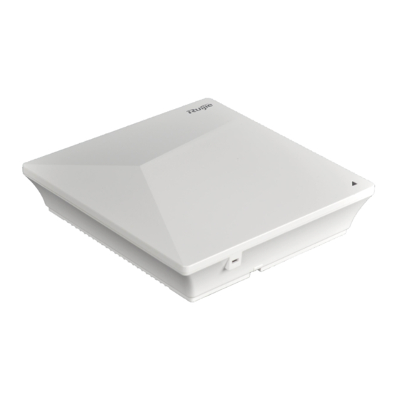
Page 5: Product Image
· Supports local power supply, DC 48V. (The power adapter is optional.) Power Supply supports the IEEE 802.3af standard Power Consumption Maximum: 12.95W Operating temperature: -10 º C to 50 º C Storage temperature: -40 º C to 70 º C Environment Operating humidity: 5% to 95%(non-condensing) Storage humidity: 5% to 95% (non-condensing) - Page 6 · Fit AP LED State Blinking Frequency Meaning The AP is NOT receiving power/ in the do-not-disturb status. This state can be disabled via software. Blinking green 3 Hz Initialization in progress. Blinking red 3 Hz Initialization is complete, but no Ethernet activity on either Ethernet port.
-
Page 7: Power Sources
· Remarks ④ 1000BASE-T/100BASE-TX/10BASE-T auto-sensing Ethernet port (PoE-capable) 1.3 Power Sources The AP can be powered either with a power adapter or through Power over Ethernet (PoE). To use a PoE device, make sure it supports the IEEE 802.3af/at PoE standard. 1.4 Cooling Solution The AP adopts fanless design. - Page 8 · Figure 1-4 Preferred Ceiling-Mount and Wall-Mount Orientations of the RG-AP530-I V2 (in the 5 GHz Band)
-
Page 9: Preparing For Installation
· 2 Preparing for Installation Precautions To prevent device damage and bodily injury, please read carefully the safety recommendations described in this chapter. The recommendations do not cover all possible hazardous situations. Installation Safety Do not expose the AP to high temperature, dusts, or harmful gases. ... -
Page 10: Temperature And Humidity
· Keep the AP away from radio stations, radar stations, high-frequency high-current devices, and microwave ovens. Any nonstandard and inaccurate electrical operation can cause an accident such as fire or electric shock, thus causing severe even fatal damages to human bodies and device. Direct or indirect touch through a wet object on high voltage and power line can bring a fatal danger. -
Page 11: Power Supply
PoE injector: IEEE 802.3af/802.3at compliant The DC input power should be greater than the power actually consumed by the system. The input power for the RG-AP530-I should not be lower than 12.95 W. Please use Ruijie certified PoE injectors. 2.7 Installation Tools Common Tools... - Page 12 · Verify that all parts are installed and debugged. Screws Items Mounting brackets Product quick installation guide Packing list The above listed items are for general situations, which may vary in the actual shipment. The purchase order shall prevail in any case. Please check each item carefully according to the packing list or purchase order. If any item is damaged or missing, notify the sales person.
-
Page 13: Installing The Access Point
· 3 Installing the Access Point Before installing the AP, make sure you have carefully read the requirements described in Chapter 2, and the requirements are met. 3.1 Installation Flowchart Figure 3-1 Installation Flowchart of the RG-AP530-I V2 3.2 Before You Begin Before you install the AP, verify that: ... - Page 14 · Install the device indoors. Do not expose the device in a thunderstorm or strong electric field. Keep the device clean and dust-free. Disconnect the device before cleaning it. Do not wipe the device with a damp cloth. ...
- Page 15 · Figure 3-3 Mounting the AP on the Bracket The AP can be installed in any of four directions on the mounting bracket depending on how you route your Ethernet cable. The square feet should fit easily into the mounting slots. Do not forcibly push the AP into the slots. After installation, verify that the AP is securely fastened.
-
Page 16: Optional) Securing The Access Point
Figure 3-6 Mounting the AP on the Bracket When mounting the AP on the wall, keep the logo of Ruijie point upward. The square feet should fit easily into the mounting slots. Do not forcibly push the AP into the slots. -
Page 17: Removing The Access Point
· Before mounting the AP on the bracket, you must first install the Ethernet cables. Install the padlock. Figure 3-9 Installing the padlock The padlocks are optional and customer-supplied. 3.6 Removing the Access Point If a padlock is installed, unlock it first. Figure 3-10 Unlocking the padlock Hold the AP in your hands and push it upward in the LAN port direction. -
Page 18: Connecting Cables
AP. The console port is used only when you want to configure the AP manually. Avoid bending the cable to a small radius close to the connector. Ruijie recommends you not use Ethernet cables with protective sleeves that may cause inconvenience to installation of Ethernet cables. -
Page 19: Checking After Installation
· Extend the cables under the AP and run in straight line. 3.9 Checking after Installation Checking the Cabinet Make sure the external power supply matches the specifications of the patch panel in the cabinet. After installation, make sure you can close the front and rear cabinet doors. ... -
Page 20: System Debugging
· 4 System Debugging 4.1 Setting up a Debugging Environment Use a power adapter or PoE to power the AP. Setting up the Environment Verify that the AP is properly connected to the power source. Connect the AP to an AC through a twisted pair cable. ... -
Page 21: Monitoring And Maintenance
Hardware Installation and Reference Guide Monitoring and Maintenance · 5 Monitoring and Maintenance 5.1 Monitoring You can observe the LED to monitor the AP in operation. Blinking green: The AP is being initialized. Blinking red: The AP completes initialization but has no Ethernet activity. ... -
Page 22: Troubleshooting Flowchart
Hardware Installation and Reference Guide Troubleshooting · 6 Troubleshooting 6.1 Troubleshooting Flowchart 6.2 Troubleshooting LED does not light up after the AP is powered on If you use PoE power supply, verify that the power source is IEEE 802.11af compliant, and then verify that the cable is connected properly. - Page 23 Hardware Installation and Reference Guide Troubleshooting Follow the above-mentioned two steps. · Verify that the AP is configured correctly. Adjust the angle of antennas. Move the client device to adjust the distance between the client and the AP. LED keeps blinking red The LED stays blinking red for a long time, indicating the Ethernet port is not connected.
-
Page 24: Appendix A Connectors And Media
Hardware Installation and Reference Guide Appendix A Connectors and Media · 7 Appendix A Connectors and Media 1000BASE-T/100BASE-TX/10BASE-T The 1000BASE-T/100BASE-TX/10BASE-T is a 10/100/1000 Mbps auto-negotiation port that supports auto MDI/MDIX. Compliant with IEEE 802.3ab, 1000BASE-T requires Category 5e 100-ohm UTP or STP (STP is recommended) with a maximum distance of 100 meters (328 feet). -
Page 25: Appendix B: Cabling Recommendations
Hardware Installation and Reference Guide Appendix Cabling Recommendations · 8 Appendix B: Cabling Recommendations During installation, route cable bundles upward or downward along the sides of the rack depending on the actual situation in the equipment room. All cable connectors should be placed at the bottom of the cabinet rather than be exposed outside of the cabinet. - Page 26 Hardware Installation and Reference Guide Appendix Cabling Recommendations Cut off excess cable tie cleanly with no sharp edges after bundling cables, as shown in Figure D-2. · Figure D-2 Cutting off Excess Cable Tie If cables are to be bent, bind them first but do not tie cable ties within the bend to avoid stress on the cables, which may otherwise cause the wires inside to break, as shown in Figure D-3.
- Page 27 Hardware Installation and Reference Guide Appendix Cabling Recommendations · Spring washer Flat washer Note Flat washer When using a stiff cable, fix it near the cable lug to avoid stress on the lug and cable. Do not use self-tapping screws to fasten terminals. ...
Need help?
Do you have a question about the RG-AP530-I V2 Series and is the answer not in the manual?
Questions and answers