Table of Contents
Advertisement
Advertisement
Table of Contents

Related Manuals for Ruijie RG-AP740-I Series


Summary of Contents for Ruijie RG-AP740-I Series
- Page 1 RG-AP740-I Series Access Point Hardware Installation and Reference Guide V1.0...
-
Page 2: Copyright Statement
Ruijie Networks reserves all copyrights of this document. Any reproduction, excerption, backup, modification, transmission, translation or commercial use of this document or any portion of this document, in any form or by any means, without the prior written consent of Ruijie Networks is prohibited. are registered trademarks of Ruijie Networks. -
Page 3: Obtaining Technical Assistance
It is intended for the users who have some experience in installing and maintaining network hardware. At the same time, it is assumed that the users are already familiar with the related terms and concepts. Obtaining Technical Assistance Ruijie Networks Website: http://www.ruijienetworks.com/ Service Email: service_rj@ruijienetworks.com ... -
Page 4: Chapter 1 Product Overview
· Chapter 1 Product Overview Onboard with Ruijie’s highly acclaimed Smart Antenna, the RG-AP740-I AP tops the class by supporting 802.11ac Wave 2. Featuring 4 spatial streams and MU-MIMO, the AP implements a leading tri-radio, dual-band design. The two main radios deliver up to 1,733Mbps + 800Mbps access rates and the third offers frequency spectrum scanning. - Page 5 Hardware Installation and Reference Guide Product Overview 11ac HT160(80+80): -74dBm (MCS0), -50dBm (MCS9) · ≤100mw (20dBm) Transmit Power Transmit Power 1 dBm Adjustment Physical Dimensions 230mm x 230mm x 47mm (W x D x H) Weight 1.3 kg (host and bracket) Two 10/100/1000BASE-T Ethernet uplink ports (PoE-capable);...
- Page 6 Hardware Installation and Reference Guide Product Overview encryption mechanism, and VLAN attributes · for each SSID WDS (bridge mode) Support Remote Intelligent Perception Technology Support (RIPT) X-speed Support Intelligent load balancing based on the number Support of users or traffic STA control SSID/radio-based Bandwidth control...
-
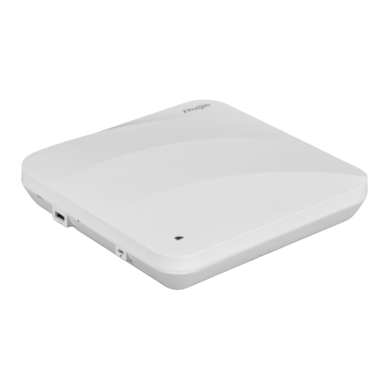
Page 7: Product Image
Hardware Installation and Reference Guide Product Overview · Product Image The AP provides two 10/100/1000Base-T Ethernet ports (PoE-capable), one Console port, one power port for external power supply, one USB port and one reset button. Figure 1-1 Image of RG-AP740-I Note 1. -
Page 8: Power Sources
The AP can be powered either with a power adapter or through Power over Ethernet (PoE). The AP requires Ruijie power adapters (If needed, you can buy them from Ruijie). To use a PoE device, make sure it supports the IEEE 802.3af/at PoE standard. -
Page 9: Radiation Pattern
· Radiation Pattern RG-AP740-I adopts the Ruijie’s Patent X-Sense Smart Antenna. Regardless of the high mobility of smart device, the AP always provides the best signal path with the revolutionary change brought by Ruijie X-Sense Smart Antenna technology. Three radio patterns are shown in the following disgrams.. Because the antennas focus gains in front of the AP, signal strength in the front is stronger. - Page 10 Hardware Installation and Reference Guide Product Overview ·...
-
Page 11: Chapter 2 Preparing For Installation
Hardware Installation and Reference Guide Preparing for Installation · Chapter 2 Preparing for Installation To prevent device damage and bodily injury, please read carefully the safety recommendations described in this chapter. The recommendations do not cover all possible hazardous situations. Installation The AP must be installed indoors. -
Page 12: Temperature And Humidity
Hardware Installation and Reference Guide Preparing for Installation Find out the location of the emergency power supply switch in the room before installation. First cut off the power · supply in case of an accident. Be sure to make a careful check before you shut down the power supply. ... -
Page 13: Power Supply
The DC input power should be greater than the power actually consumed by the system. The input power for the RG-AP740-I should not be lower than 25.5 W. Please use Ruijie recommended power adapters. Please use Ruijie certified PoE injectors. -
Page 14: Unpacking The Access Point
Hardware Installation and Reference Guide Preparing for Installation · Unpacking the Access Point Package Contents Verify that all parts are installed and debugged. Screws Mounting brackets Items Product quick installation guide Packing list The above listed items are for general situations, which may vary in the actual shipment. The purchase order shall prevail in any case. -
Page 15: Chapter 3 Installing The Access Point
Installing the Access Point · Chapter 3 Installing the Access Point The RG-AP740-I series must be fixed and installed indoors. Before installing the AP, make sure you have carefully read the requirements described in Chapter 2. Installation Flowchart Before You Begin Before you install the AP, verify that: ... - Page 16 Hardware Installation and Reference Guide Installing the Access Point Disconnect the device before cleaning it. · Do not wipe the device with a damp cloth. Do not wash the device with liquid. Do not open the enclosure when the AP is working. ...
- Page 17 Hardware Installation and Reference Guide Installing the Access Point · Before mounting the AP on the bracket, you must first install the Ethernet cables. Slide the AP onto the bracket in the reverse direction against the arrow on the mounting bracket until it clicks into place.
- Page 18 Slide the AP into the holes in the reverse direction against the arrow on the mounting bracket until it clicks into place. Note: the “Ruijie” logo is facing up. See Figure 3-6. Figure 3-6 Mounting the AP on the Bracket...
-
Page 19: (Optional) Securing The Access Point
Installing the Access Point · When mounting the AP on the wall, keep the logo of Ruijie point upward. The square feet should fit easily into the mounting slots. Do not forcibly push the AP into the slots. After installation, verify that the AP is securely fastened. -
Page 20: Removing The Access Point
Hardware Installation and Reference Guide Installing the Access Point · Before mounting the AP on the bracket, you must first install the Ethernet cables. Removing the Access Point If the AP is locked, insert the key to the bottom of a lock slot, and drive the AP in the corresponding direction as shown in Figure 3-9. -
Page 21: Connecting Cables
AP. The console port is used only when you want to configure the AP manually. Avoid bending the cable to a small radius close to the connector. Ruijie recommends you not use Ethernet cables with protective sleeves that may cause inconvenience to installation of Ethernet cables. -
Page 22: Bundling Cables
Hardware Installation and Reference Guide Installing the Access Point · Bundling Cables Precautions Make sure the cable bundles are neat and orderly. Bend twisted pairs naturally or to a large radius close to the connector. Do not over tighten cable bundle as it may reduce the cable life and performance. Bundling Steps Bundle the drop UTP/STP cables and route them to the LAN1/PoE port. -
Page 23: Chapter 4 System Debugging
Hardware Installation and Reference Guide System Debugging · Chapter 4 System Debugging Setting up a Debugging Environment Use a power adapter or PoE to power the AP. Setting up the Environment Verify that the AP is properly connected to the power source. ... -
Page 24: Chapter 5 Monitoring And Maintenance
Hardware Installation and Reference Guide Monitoring and Maintenance · Chapter 5 Monitoring and Maintenance Monitoring You can observe the LED to monitor the AP in operation. Blinking green: The AP is being initialized. Blinking red: The AP completes initialization but has no Ethernet activity. ... -
Page 25: Chapter 6 Troubleshooting
Hardware Installation and Reference Guide Troubleshooting · Chapter 6 Troubleshooting Troubleshooting Flowchart Troubleshooting LED does not light up after the AP is powered on If you use PoE power supply, verify that the power source is IEEE 802.11af compliant, and then verify that the cable is connected properly. - Page 26 Hardware Installation and Reference Guide Troubleshooting Wireless client cannot find the AP · Follow the above-mentioned two steps. Verify that the AP is configured correctly. Adjust the angle of antennas. Move the client device to adjust the distance between the client and the AP. LED keeps blinking red The LED stays blinking red for a long time, indicating the Ethernet port is not connected.
-
Page 27: Appendix A Connectors And Media
Hardware Installation and Reference Guide Appendix A Connectors and Media · Appendix A Connectors and Media 1000BASE-T/100BASE-TX/10BASE-T The 1000BASE-T/100BASE-TX/10BASE-T is a 10/100/1000 Mbps auto-negotiation port that supports auto MDI/MDIX. Compliant with IEEE 802.3ab, 1000BASE-T requires Category 5e 100-ohm UTP or STP (STP is recommended) with a maximum distance of 100 meters (328 feet). - Page 28 Hardware Installation and Reference Guide Appendix A Connectors and Media ·...
-
Page 29: Appendix B: Cabling Recommendations
Hardware Installation and Reference Guide Appendix B: Cabling Recommendations · Appendix B: Cabling Recommendations During installation, route cable bundles upward or downward along the sides of the rack depending on the actual situation in the equipment room. All cable connectors should be placed at the bottom of the cabinet rather than be exposed outside of the cabinet. - Page 30 Hardware Installation and Reference Guide Appendix B: Cabling Recommendations · If cables are to be bent, bind them first but do not tie cable ties within the bend to avoid stress on the cables, which may otherwise cause the wires inside to break, as shown in Figure B-3. Figure B-3 Do Not Tie Cable Ties within the Bend ...
- Page 31 Hardware Installation and Reference Guide Appendix B: Cabling Recommendations · 3. Spring washer 1. Flat washer Note 4. Flat washer 2. Nut When using a stiff cable, fix it near the cable lug to avoid stress on the lug and cable. ...
Need help?
Do you have a question about the RG-AP740-I Series and is the answer not in the manual?
Questions and answers