
Related Manuals for Ruijie RG-AP820-L(V2) Series


Summary of Contents for Ruijie RG-AP820-L(V2) Series
- Page 1 Ruijie RG-AP820-L(V2) Series Access Points Hardware Installation and Reference Guide V1.00...
- Page 2 Ruijie Networks reserves all copyrights of this document. Any reproduction, excerption, backup, modification, transmission, translation or commercial use of this document or any portion of this document, in any form or by any means, without the prior written consent of Ruijie Networks is prohibited. Exemption statement This document is provided “as is”.
- Page 3 It is intended for the users who have some experience in installing and maintaining network hardware. At the same time, it is assumed that the users are already familiar with the related terms and concepts. Obtaining Technical Assistance Ruijie Networks Website: https://www.ruijienetworks.com/ Technical Support Website: https://ruijienetworks.com/support...
-
Page 4: Product Overview
· 1 Product Overview Featuring leading 802.11ax, Ruijie RG-AP820-L(V2) delivers up to 575Mbps@2.4G and 1.2Gbps@5G. The overall dual-radio, dual-band performance speeds up to 1.775Gbps per device, totally eliminating Gigabit wireless bottlenecks. 1.1 Technical Specifications Table 1-1 Technical Specifications of RG-AP820-L(V2) -
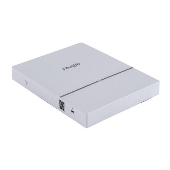
Page 5: Product Image
· Dimensions 193 mm x153 mm x 26 mm (7.60 in x 6.02 in x 1.02 in) (W x D x H) ≤ 1 kg (2.20 lbs) Weight One 10/100/1000BASE-T Ethernet port (802.3af PoE-capable) Service Ports Management Ports One RJ45 Console port supports 9600bps, 57600bps and 115200bps. Button One Reset button Anti-Theft Lock... -
Page 6: Led Indicators
· Note 1. Reset button 4. RJ45 Console port 2. LED indicator 5. LAN/PoE port 3. Anti-Theft lock hole 6. 48V DC power port 1.3 LED Indicators Fit AP State Frequency Meaning The AP is NOT receiving power. Or the AP is in Do Not Disturb mode, which can be disabled by software. -
Page 7: Power Sources
The AP can be powered either with a DC power adapter or through Power over Ethernet (PoE). The AP requires Ruijie power adapters (If needed, you can buy them from Ruijie). To use a PoE device, make sure it supports the IEEE 802.3af PoE standard. -
Page 8: Preparing For Installation
· 2 Preparing for Installation To prevent device damage and bodily injury, please read carefully the safety recommendations described in this chapter. The recommendations do not cover all possible hazardous situations. 2.1 Installation The AP must be installed indoors. To ensure its normal operation, the installation site must meet the following requirements. -
Page 9: Temperature And Humidity
· Be sure to make a careful check before you shut down the power supply. Do not place the device in a damp/wet location. Do not let any liquid enter the chassis Keep the AP far away from the grounding or lightning protection devices of power equipment. ... -
Page 10: Power Supply
· Table 2-3 Average (mg/m Maximum (mg/m 0.006 0.03 0.04 0.15 0.05 0.15 0.01 2.7 Power Supply DC power adapter: 48V/0.3A Specifications of Connector Internal Diameter External Diameter Depth Polarity 2.1mm 5.5mm 10mm Internal: positive External: negative 2.8 Installation Tools Common Tools Phillips screwdriver, related copper and fiber cables, bolts, diagonal pliers, cable ties Special Tools... - Page 11 · The above listed items are for general situations, which may vary in the actual shipment. The purchase order shall prevail in any case. Please check each item carefully according to the packing list or purchase order. If any item is damaged or missing, notify the sales person.
-
Page 12: Installing The Access Point
· 3 Installing the Access Point The RG-AP820-L(V2) series must be fixed and installed indoors. Before installing the AP, make sure you have carefully read the requirements described in Chapter 2. 3.1 Installation Flowchart 3.2 Before You Begin Before you install the AP, verify that: ... - Page 13 · Disconnect the device before cleaning it. Do not wipe the device with a damp cloth. Do not wash the device with liquid. Do not open the enclosure when the AP is working. Fasten the device tightly. 3.4 Installing the Access Point ...
- Page 14 · Figure 3-2 Aligning the Square Feet with the Mounting Holes Before mounting the AP on the bracket, you must first install the Ethernet cables. Slide the AP onto the bracket in the reverse direction against the arrow on the mounting bracket until it clicks into place.
- Page 15 · Figure 3-4 Attaching the Mounting Bracket on the Wall Align the square feet on the rear of the AP over the mounting holes on the bracket. See Figure 3-5. Figure 3-5 Aligning the Square Feet with the Mounting Holes Before mounting the AP on the bracket, you must first install the Ethernet cables.
-
Page 16: Removing The Access Point
Figure 3-6 Mounting the AP on the Bracket When mounting the AP on wall, keep the “Ruijie” logo upright during the installation. The square feet should fit easily into the mounting slots. Do not forcibly push the AP into the slots. -
Page 17: Connecting Cables
· Figure 3-11 Removing the Ceiling-Mount AP 3.6 Connecting Cables Connect UTP/STP to the LAN/PoE port on the AP. See Appendix A for supported wiring of twisted pairs. By default, baud rate is set to 9600, data bit 8, parity none, stop bits 1 and flow control none on the console port of the AP. - Page 18 · Make sure the device and all cables are securely fastened in the rack. Checking Cable Connection Make sure the UTP/STP cable matches the interface type. Make sure cables are properly bundled. Checking the Power Supply Make sure all power cables are properly connected and safe.
-
Page 19: System Debugging
· 4 System Debugging 4.1 Setting up a Debugging Environment Use a power adapter or PoE to power the AP. Setting up the Environment Verify that the AP is properly connected to the power source. Connect the AP to an AC through a twisted pair cable. ... -
Page 20: Monitoring And Maintenance
· 5 Monitoring and Maintenance 5.1 Monitoring You can observe the LED to monitor the AP in operation. CLI Commands You can run related commands on the command line interface (CLI) on the AC to remotely monitor the configurations and status of the AP. -
Page 21: Troubleshooting Flowchart
· 6 Troubleshooting 6.1 Troubleshooting Flowchart 6.2 Troubleshooting LED does not light up after the AP is powered on If you use PoE power supply, verify that the power source is IEEE 802.11af compliant, and then verify that the cable is connected properly. - Page 22 · Follow the above-mentioned two steps. Verify that the AP is configured correctly. Adjust the angle of antennas. Move the client device to adjust the distance between the client and the AP. LED keeps blinking red The LED stays blinking red for a long time, indicating the Ethernet port is not connected. Verify the Ethernet connection. LED keeps blinking green The AP performs initialization after power on.
-
Page 23: Appendix A: Connectors And Media
· Appendix A: Connectors and Media 1000BASE-T/100BASE-TX/10BASE-T The 1000BASE-T/100BASE-TX/10BASE-T is a 10/100/1000 Mbps auto-negotiation port that supports auto MDI/MDIX. Compliant with IEEE 802.3ab, 1000BASE-T requires Category 5e 100-ohm UTP or STP (STP is recommended) with a maximum distance of 100 meters (328 feet). 1000BASE-T requires all four pairs of wires be connected for data transmission, as shown in Figure A-1. -
Page 24: Appendix B: Cabling Recommendations
· Appendix B: Cabling Recommendations During installation, route cable bundles upward or downward along the sides of the rack depending on the actual situation in the equipment room. All cable connectors should be placed at the bottom of the cabinet rather than be exposed outside of the cabinet. - Page 25 · If cables are to be bent, bind them first but do not tie cable ties within the bend to avoid stress on the cables, which may otherwise cause the wires inside to break, as shown in Figure B-3. Figure B-3 Do Not Tie Cable Ties within the Bend ...
- Page 26 · 3. Spring washer 1. Flat washer Note 4. Flat washer 2. Nut When using a stiff cable, fix it near the cable lug to avoid stress on the lug and cable. Do not use self-tapping screws to fasten terminals. ...
Need help?
Do you have a question about the RG-AP820-L(V2) Series and is the answer not in the manual?
Questions and answers