Table of Contents
Advertisement
Quick Links
Advertisement
Table of Contents

Subscribe to Our Youtube Channel
Related Manuals for Ruijie RG-AP520 Series


Summary of Contents for Ruijie RG-AP520 Series
- Page 1 RG-AP520 Series Access Point Hardware Installation and Reference Guide V1.0...
-
Page 2: Copyright Statement
Ruijie Networks reserves all copyrights of this document. Any reproduction, excerption, backup, modification, transmission, translation or commercial use of this document or any portion of this document, in any form or by any means, without the prior written consent of Ruijie Networks is prohibited. are registered trademarks of Ruijie Networks. -
Page 3: Obtaining Technical Assistance
It is intended for the users who have some experience in installing and maintaining network hardware. At the same time, it is assumed that the users are already familiar with the related terms and concepts. Obtaining Technical Assistance Ruijie Networks Website: http://www.ruijienetworks.com/ Service Email: service_rj@ruijienetworks.com ... -
Page 4: Chapter 1 Product Overview
Chapter 1 Product Overview RG-AP520 is a wireless LAN access point (AP) designed by Ruijie Networks for demanding indoor deployments. It can serve as a Fit AP and operate in conjunction with a unified wired/wireless switch or a wireless controller; or it can serve as a standalone Fat AP and provide wireless access for mobile clients. - Page 5 · 1 LED (red, green, blue, orange, and flashing modes, breathing flashing mode for smart device access, and the indicator can be switched off to silent mode) Power Supply Adapter: DC 12V (optional) PoE: IEEE 802.3af/802.3at-compliant (compatible). Power Consumption Maximum: 12.95W Operating: -10 to 55℃...
-
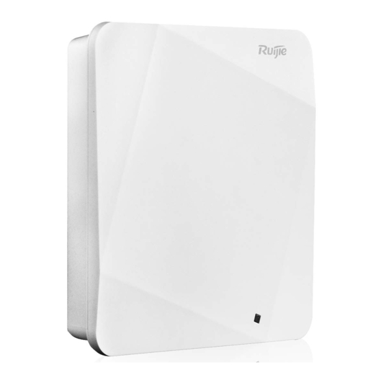
Page 6: Product Image
· Fault detection and alarm Support Statistics and logs Support FAT/FIT switching Support 128 (The actual number of users depends on Maximum stations per AP environmental factors.) The recommended number of stations per AP Virtual AP A maximum of 32 SSIDs SSID hiding Support Configuring the authentication mode,... -
Page 7: Led Indicators
· LED Indicators Fit AP State Frequency Meaning The AP is NOT receiving power. Or the AP is in Do Not Disturb mode, which can be disabled by software. Blinking green Initialization in progress Solid green Initialization in progress Blinking red Initialization is complete, but no Ethernet activity. -
Page 8: Power Sources
The AP can be powered either with a power adapter or through Power over Ethernet (PoE). The AP requires Ruijie power adapters (If needed, you can buy them from Ruijie). To use a PoE device, make sure it supports the IEEE 802.3af/at PoE standard. -
Page 9: Chapter 2 Preparing For Installation
· Chapter 2 Preparing for Installation To prevent device damage and bodily injury, please read carefully the safety recommendations described in this chapter. The recommendations do not cover all possible hazardous situations. Installation The AP must be installed indoors. To ensure its normal operation, the installation site must meet the following requirements. -
Page 10: Temperature And Humidity
· Find out the location of the emergency power supply switch in the room before installation. First cut off the power supply in case of an accident. Be sure to make a careful check before you shut down the power supply. ... -
Page 11: Power Supply
The DC input power should be greater than the power actually consumed by the system. The input power for the RG-AP520 should be greater than 12.95 W. Please use Ruijie recommended power adapters. Please use Ruijie certified PoE injectors. Installation Tools... -
Page 12: Unpacking The Access Point
· Unpacking the Access Point Package Contents Verify that all parts are installed and debugged. Screws Mounting brackets Items Product quick installation guide Packing list The above listed items are for general situations, which may vary in the actual shipment. The purchase order shall prevail in any case. -
Page 13: Chapter 3 Installing The Access Point
· Chapter 3 Installing the Access Point The RG-AP520 series must be fixed and installed indoors. Before installing the AP, make sure you have carefully read the requirements described in Chapter 2. Installation Flowchart Before You Begin Before you install the AP, verify that: ... - Page 14 · Disconnect the device before cleaning it. Do not wipe the device with a damp cloth. Do not wash the device with liquid. Do not open the enclosure when the AP is working. Fasten the device tightly. Installing the Access Point ...
- Page 15 · The AP can be installed in any of four directions on the mounting bracket depending on how you route your Ethernet cable. The square feet should fit easily into the mounting slots. Do not forcibly push the AP into the slots. After installation, verify that the AP is securely fastened.
-
Page 16: Securing The Access Point
Figure 3-6 Mounting the AP on the Bracket When mounting the AP on the wall, keep the logo of Ruijie point upward. The square feet should fit easily into the mounting slots. Do not forcibly push the AP into the slots. - Page 17 · Press the button and unplug the lock hasp. Align the lock loop protruding from the AP with the lock hasp hole. Figure 3-2 Aligning the Lock Loop with the Lock Hasp Before mounting the AP on the bracket, you must first install the Ethernet cables. Install the padlock.
-
Page 18: Removing The Access Point
· Install the padlock as needed. Padlocks are customer supplied. Removing the Access Point Remove the padlock if there is one. Figure 3-4 Removing the Padlock If the AP is installed on the wall, hold the AP in your hands and push it upward and away from the bracket in the LAN port direction. -
Page 19: Connecting Cables
AP. The console port is used only when you want to configure the AP manually. Avoid bending the cable to a small radius close to the connector. Ruijie recommends you not use Ethernet cables with protective sleeves that may cause inconvenience to installation of Ethernet cables. -
Page 20: Checking The Power Supply
· Make sure the external power supply matches the specifications of the patch panel in the cabinet. After installation, make sure you can close the front and rear cabinet doors. Make sure the cabinet is stable and level. ... -
Page 21: Chapter 4 System Debugging
· Chapter 4 System Debugging Setting up a Debugging Environment Use a power adapter or PoE to power the AP. Setting up the Environment Verify that the AP is properly connected to the power source. Connect the AP to an AC through a twisted pair cable. ... -
Page 22: Chapter 5 Monitoring And Maintenance
· Chapter 5 Monitoring and Maintenance Monitoring You can observe the LED to monitor the AP in operation. Blinking green: The AP is being initialized. Blinking red: The AP completes initialization but has no Ethernet activity. Blinking blue: The AP completes initialization and is establishing a CAPWAP connection with the AC. ... -
Page 23: Chapter 6 Troubleshooting
· Chapter 6 Troubleshooting Troubleshooting Flowchart Troubleshooting LED does not light up after the AP is powered on If you use PoE power supply, verify that the power source is IEEE 802.11af compliant, and then verify that the cable is connected properly. If you use a power adapter, verify that the power adapter is connected to an active power outlet, and then verify that the power adapter works properly. - Page 24 · Wireless client cannot find the AP Follow the above-mentioned two steps. Verify that the AP is configured correctly. Adjust the angle of antennas. Move the client device to adjust the distance between the client and the AP. LED keeps blinking red The LED stays blinking red for a long time, indicating the Ethernet port is not connected.
-
Page 25: Appendix A Connectors And Media
· Appendix A Connectors and Media 1000BASE-T/100BASE-TX/10BASE-T The 1000BASE-T/100BASE-TX/10BASE-T is a 10/100/1000 Mbps auto-negotiation port that supports auto MDI/MDIX. Compliant with IEEE 802.3ab, 1000BASE-T requires Category 5e 100-ohm UTP or STP (STP is recommended) with a maximum distance of 100 meters (328 feet). 1000BASE-T requires all four pairs of wires be connected for data transmission, as shown in Figure A-1. - Page 26 ·...
-
Page 27: Appendix B: Cabling Recommendations
· Appendix B: Cabling Recommendations During installation, route cable bundles upward or downward along the sides of the rack depending on the actual situation in the equipment room. All cable connectors should be placed at the bottom of the cabinet rather than be exposed outside of the cabinet. - Page 28 · If cables are to be bent, bind them first but do not tie cable ties within the bend to avoid stress on the cables, which may otherwise cause the wires inside to break, as shown in Figure B-3. Figure B-3 Do Not Tie Cable Ties within the Bend ...
- Page 29 · 3. Spring washer 1. Flat washer Note 4. Flat washer 2. Nut When using a stiff cable, fix it near the cable lug to avoid stress on the lug and cable. Do not use self-tapping screws to fasten terminals. ...
Need help?
Do you have a question about the RG-AP520 Series and is the answer not in the manual?
Questions and answers