
Related Manuals for Circutor CVM-BDM


Summary of Contents for Circutor CVM-BDM
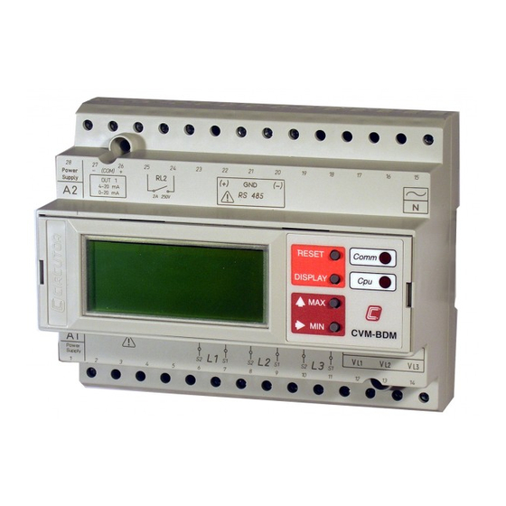
- Page 1 SUPPLY NETWORK ANALYZER CVM-BDM SERIES INSTRUCTION MANUAL ( M98153001-03 / 06C ) CIRCUTOR S.A.
-
Page 2: Table Of Contents
2.1.- Other features ..................6 2.2.- Types of CVM-BDM ................7 INSTALLATION AND STARTUP ............7 3.1.- Installation..................... 8 3.2.- CVM-BDM Connection terminal (see side labels) ....... 10 3.3.- Connection drawing for the CVM-BDM: ..........11 OPERATION MODE................15 SETUP PROCEDURE ................. 17 5.1.- Phase-to-Phase or Phase-to-Neutral voltages........ - Page 3 12.3.- MODBUS © protocol................ 47 13.- APPENDIX................... 53 13.1.- Appendix A: Four quadrant measuring method in the CVM-BDM..53 13.2.- Appendix B: Second SETUP of the CVM-BDM......... 54 13.3.- Appendix C: Internal memory reading and setting procedures ..56 13.3.1.- Description .................. 56 13.3.2.- Internal memory setting for data collection purposes....
-
Page 4: Basic Instructions
1.- BASIC INSTRUCTIONS 1.1.- Delivery spot check This manual is issued to help all the CVM-BDM users to install and use it in order to get the best from it. After receiving the unit please check the following points: (a) Does this device corresponds to your order specifications? (b) Check if any damage was done during the shipment process. -
Page 5: Main Characteristics
Before power supplying the instrument, read the CONNECTIONS and SETUP sections and choose the most suitable operation mode for getting your desired data. The CVM-BDM is an instrument which measures, calculates, displays and memorizes all the main electrical parameters at any electrical network (balanced or not). - Page 6 (+) and (--) Reactive energy (capacitive), two indep. meters kvarh.C (+) and (--) CVM-BDM permits above enumerated parameters to be view in a three-line alphanumeric display. Three parameters are shown in every screen. (a) Phase-to-neutral or phase-to-phase voltage of every phase.
-
Page 7: Other Features
"now". --------------------------------------------------------------------------------------------- CVM-BDM is equipped with an internal memory for the collection of main parameters from the electric network. By means of the PC see, the user can select the parameters to be save into memory among all measured by the power meter (instantaneous, maximum and minimum values). -
Page 8: Types Of Cvm-Bdm
7 70 293 CVM-BDM-420 CVM-BDM + 2 analog outputs Different CVM-BDM... provide more parameters to be displayed (additional SETUP). 3.- INSTALLATION AND STARTUP The manual you hold in your hands contains information and warnings that the user should respect in order to guarantee a proper operation of all the instrument functions and keep its safety conditions. -
Page 9: Installation
Maximum voltage at the voltage measuring circuit: Standard: 500 V a.c. phase-neutral / 866 V c.a. between phases A special model CVM-BDM for 110 V measurement is also available: 100 V a.c. phase-neutral / 173 V a.c. between phases c.- Maximum admissible current : Transformer of In / 5 A a.c. - Page 10 CVM-BDM supply network analyzer ----- -------- --- Page Nº Installation : The instrument is to be fit onto a DIN 46277 (EN 50022) rail . All connections keep inside the cabinet. Note that with the instrument powered on, the terminals could be dangerous to touching and cover opening actions or elements removal may allow accessing dangerous parts.
-
Page 11: Cvm-Bdm Connection Terminal (See Side Labels)
.../ 5 A 9 - 8 I L2: s1 - s2 Current phase L2 .../ 5 A 7 - 6 I L1: s1 - s2 Current phase L1 ... / 5 A NOTE: Current inputs are isolated in the CVM-BDM model... -
Page 12: Connection Drawing For The Cvm-Bdm
CVM-BDM supply network analyzer ----- -------- --- Page Nº 3.3.- Connection drawing for the CVM-BDM: a.- CVM-BDM: Three-phase network.- 4 wires (low voltage) : CVM-BDM P1 S2 P1 S2... - Page 13 CVM-BDM supply network analyzer ----- -------- --- Page Nº b.- CVM-BDM: 3 current transformers + 2 voltage transformer : POWER SUPPLY CVM-BDM 10 11 12 13 14...
- Page 14 CVM-BDM supply network analyzer ----- -------- --- Page Nº c.- CVM-BDM: 2 current transformers + 2 voltage transformer. S2 of the current transformer grounded to earth POWER SUPPLY CVM-BDM 10 11 12 13 14...
- Page 15 CVM-BDM supply network analyzer ----- -------- --- Page Nº S1 of the current transformer grounded to earth POWER SUPPLY CVM-BDM 10 11 12 13 14...
-
Page 16: Operation Mode
----- -------- --- Page Nº 4.- OPERATION MODE The instrument has a display with three lines (10 characters every line). When you switch on the power supply of the CVM-BDM you will see on the display: Card Circ Where: xxxxx utor xxxx = hardware configuration. - Page 17 CVM-BDM supply network analyzer ----- -------- --- Page Nº Pressing the "max" key, the maximum values for the parameters being shown appear in the displays. xxxx xxxx xxxx This function is only valid while you keep pressing the "max" key. If you stop pressing the key the instantaneous values appear again.
-
Page 18: Setup Procedure
-------- --- Page Nº 5.- SETUP PROCEDURE The setup procedure of the CVM-BDM is performed by means of several SETUP options. For accessing the setup menu the keys max & min must be simultaneously pressed once the instrument is at the main screen. -
Page 19: Phase-To-Phase Or Phase-To-Neutral Voltages
CVM-BDM supply network analyzer ----- -------- --- Page Nº 5.1.- Phase-to-Phase or Phase-to-Neutral voltages After the word "set" you will see on the three displays the voltages of the phases L1, L2, L3. Phase to Neutral Voltages: U1 , U2 , U3... -
Page 20: Voltage Transformation Ratio
CVM-BDM supply network analyzer ----- -------- --- Page Nº 5.2.- Voltage transformation ratio. 5.2.1.- Voltage Transformer Primary. On the screen we read the word "SET U P" followed by 6 digits. They allow us setting the primary of the voltage transformer. -
Page 21: Voltage Transformer Secondary
The procedure is the same one done at the previous sections with the "max", "min" and "display" keys. If the CVM-BDM is directly connected to the mains (without voltage transformer) the values of primary and secondary must be the same, for instance 000001/001. -
Page 22: Network Specifications
CVM-BDM supply network analyzer ----- -------- --- Page Nº 5.4.- Network specifications 5.4.1.- Rated voltage The message "SET n" is on screen, together with three digits to set the rated voltage of the monitored power system. Whether the voltage measurement is carried out through the secondary of voltage transformers, then the rated voltage of the transformer secondary must be set. -
Page 23: Integration Period Of Voltage And Frequency Signals
"display" keys. For the calculation of the average, maximum and minimum voltage and frequency values, the CVM-BDM obtains one value every second. These values equal the average of the values calculated within the time window set by the user (time constant). If the time value is 1 second, then the viewed value equals the... -
Page 24: Parameter Setup
This option allows to program until 45 optional parameters that you can see on 15 programmable pages (3 parameters every page). The CVM-BDM asks first if you want to program the default parameters. "max" key : you can select YES or NO. The “display” key allows the validation of the selected option. - Page 25 % THD V2 % THD V3 Current THD % THD I1 % THD I2 % THD I3 Flicker WA_V1 WA_V2 WA_V3 PST_V1 PST_V2 PST_V3 - For passing to the next page , press "display". In this case the CVM-BDM ask again:...
-
Page 26: First
This option allows selecting among fixed or rotary page: a.- Fixed page: the page is changed pressing the "display" key. The page among the available ones that we want to see when the CVM-BDM is supplied (or a reset is made) can be selected. -
Page 27: Maximum Power Demand
CVM-BDM supply network analyzer ----- -------- --- Page Nº 5.8.- Maximum power demand Push the key "display" and the following screens will appear by display: 1) PARAMETER TO CONTROL ("SET Pd xx") None Three phase active power kW III Three phase apparent power... -
Page 28: Date / Time Setup
CVM-BDM supply network analyzer ----- -------- --- Page Nº 5.9.- DATE / TIME SETUP Pressing the "display" key we will see in the CVM-BDM screen the following: 1.- DAY : MONTH ("SET day dd:mm") 2.- YEAR ("SET YEAR xxxx " ) 4 digits 3.- HOURS : MINUTES ("SET HOUR hh:mm") -
Page 29: Clearing Energy Counters
CVM-BDM supply network analyzer ----- -------- --- Page Nº 5.10.- Clearing energy counters On display we see "CLR ENER no" (Clear energy counters). - "max" : To select "YES" or "no" - "display" : To validate the selected option. Once finishing this option, all the modifications that we have done are saved into memory and the setup process is finished. -
Page 30: Memory Setup
CVM-BDM supply network analyzer ----- -------- --- Page Nº 5.11.- Memory SETUP Once the setup for the analyzer performance is completed, the memory is then configured. Firstly set the recording period: Per data 001 min. Recording period Recording period must be set within 1 s & 240 min. -
Page 31: Thd Or D Setting
CVM-BDM supply network analyzer ----- -------- --- Page Nº 5.12.- THD or D setting dHAR dHAR Two modes for the harmonic distortion calculation can be selected: d % : total value of the harmonic distortion referred to the fundamental value. -
Page 32: Additional Screen With The Relay Output
--- Page Nº 5.13.- Additional screen with the relay output. CVM-BDM-C2 (2 relays ) & CVM-BDM-C420 (1 relay ) With these outputs the CVM-BDM can be configured for: A.- Pulse every certain kW.h or kvar.h (ENERGY). You can define the value corresponding to the energy consumed for generating a pulse (0.5 sec. - Page 33 "max" key 0.500 kW. - For passing to the next option, press "display": setup options for the second relay will appear (only with the CVM-BDM type CVM-BDM-C2 ). OUT 2 RELAY 2...
- Page 34 MAXIMUM value MINIMUM value Delay for the conditions These screens are successively displayed by the CVM-BDM once the parameter has been selected (for the setup of each option proceed as in the Section a.-): b.1.- Programming the maximum value to be controlled:...
- Page 35 CVM-BDM supply network analyzer ----- -------- --- Page Nº ALARM ACTIVATION: The alarms depend on the programmed values of MAXIMUM and MINIMUM. MIN + MAX + Ì=======¹ max > min MIN + MAX + max < min ========¹Ì====== MIN -- MAX + Ì======¹...
- Page 36 Energies kW.h, kvar.h Power factor x.xx - 0.7 = - 0.70 Frequency xx.x 50.0 = 50 Hz Connections of the RELAY OUTPUTS : a.- CVM-BDM-C2 ( 2 relays ) : Out1 Terminals Signal Out2 Terminals Signal 27 - 26 N.O.
-
Page 37: Additional Screen With The 4 - 20 Ma Outputs
CVM-BDM-C420 (1 relay +1 analog output). With this outputs we can configure the CVM-BDM to give an output of 4 - 20 mA d.c. or of 0 - 20 mA d.c. ( resolution of 4.000 points ) proportional to any of the parameters measured by the CVM-BDM, with the ability of setting the scale (offset and full scale). - Page 38 (four digits with floating decimal point) Proceed as in the previous section. - For passing to the next option, press "display": the setup for the second output will appear (only with a CVM-BDM type CVM-BDM-420). dA 2 OUTPUT D/A No.2...
- Page 39 -------- --- Page Nº 1.- Connections of the 4- 20 mA outputs : a.- CVM-BDM-420 (Two 4-20 mA outputs : channel 1 and channel 2 ) and b.- CVM-BDM-C420 ( One 4-20 mA output : channel 1 ) Terminals Signal...
-
Page 40: Data Collection Into Memory
6.- DATA COLLECTION INTO MEMORY 6.1.- Characteristics The CVM-BDM power meter is equipped with an internal memory to store some all the electrical parameters measured or calculated by the analyzer. Data collection into memory is automatically carried out every user-defined period. -
Page 41: Memory Capacity
Parameters 6.4.- Setting the memory up from PC. The choice of parameters to be stored by the CVM-BDM must be carried out through a PC by means of the Power-Vision software. This software permits to read the SETUP saved into the own CVM-BDM, and... -
Page 42: Contrast
CVM-BDM supply network analyzer ----- -------- --- Page Nº 7.- CONTRAST. For a correct visualization of the display, you can set the display’s contrast by pressing the buttons DISPLAY+Máx to increase, and DISPLAY + Min to decrease. -
Page 43: Specifications
CVM-BDM supply network analyzer ----- -------- --- Page Nº 8.- SPECIFICATIONS Power supply : see specifications on the own CVM-BDM rear - CVM-BDM: Single phase 230 V a.c. Voltage tolerance: +10 % / -15 % Frequency: 50 ... 60 Hz Power consumption ..... -
Page 44: Safety Considerations
CVM-BDM supply network analyzer ----- -------- --- Page Nº Dimensions : 9.- SAFETY CONSIDERATIONS All installation specification described at the previous chapters named INSTALLATION AND STARTUP, INSTALLATION MODES and SPECIFICATIONS. Note that with the instrument powered on, the terminals could be dangerous to touching and cover opening actions or elements removal may allow accessing dangerous parts. -
Page 45: Maintenance
-------- --- Page Nº 10.- MAINTENANCE The CVM-BDM does not require any special maintenance. No adjustment, maintenance or repairing action should be done over the instrument open and powered and, should those actions are essential, high-qualified operators must perform them. -
Page 46: Cvm-Bdm
- PROTOCOL: MODBUS © (Question / Answer) - CVM-BDM DEFAULT CONFIGURATION : 001 / 9.600 / 8 bits / N / 1 bit - Available baud rates: 1.200 - 2.400 - 4.800 - 9.600 - 19.200 bauds - RS-485 type output: −... -
Page 47: Rs-485 Type Connection To A Rs-232 Type Input Of A Pc
CVM-BDM supply network analyzer ----- -------- --- Page Nº 12.2.- RS-485 type connection to a RS-232 type input of a PC DB-9 RS-232 CONVERTIDOR RS-232 / RS-485 RS-485 CVM-BDM *If the RS485/232 converter with RTS control ability (code 770208) is used, then... -
Page 48: Modbus © Protocol
The CVM-BDM analyzer can communicate by means of the MODBUS © protocol, as it is following described: When the CVM-BDM communicates with MODBUS protocol, it uses the RTU mode (Remote Terminal Unit ). Each 8-bits byte in a message contains two 4-bits hexadecimal characters. - Page 49 CVM-BDM supply network analyzer ----- -------- --- Page Nº a.- Registers assigned to different parameters measured by the CVM-BDM: MODBUS REGISTERS (longs) HEXA-DECIMAL PARAMETER Units PRESENT MAXIMUM MINIMUM Value Value Value Phase voltage - V 1 V x 10 00-01...
- Page 50 CVM-BDM supply network analyzer ----- -------- --- Page Nº MODBUS REGISTERS (longs) HEXA-DECIMAL PARAMETER Units PRESENT MAXIMUM MINIMUM Value Value Value Frequency (L1) - Hz Hz x 10 30-31 130-131 230-231 Three-phase apparent power kVA III 32-33 132-133 232-233 Line-to-line voltage L1-L2 - V12...
- Page 51 CVM-BDM supply network analyzer ----- -------- --- Page Nº MODBUS REGISTERS (longs) HEXA-DECIMAL PARAMETER Units PRESENT MAXIMUM MINIMUM Value Value Value Flicker WA - L1 %x10 76-77 176-177 276-277 Flicker WA - L2 %x10 78-79 178-179 278-279 Flicker WA - L3...
- Page 52 CVM-BDM supply network analyzer ----- -------- --- Page Nº EXAMPLE QUESTION 0A 03 00 24 00 10 05 76 CVMk number, 10 in decimal Reading function 00 24 Starting address (first register ) 00 10 Number of registers for reading...
- Page 53 CVM-BDM supply network analyzer ----- -------- --- Page Nº b.- Reading of digital outputs - Function 01 : Question PP0100000008CRC (PP = Peripheral No.) Answer : PP0101XXCRC where XX (hexadecimal byte) translated to binary b7 b6 b5 b4 b3 b2 b1 b0 bit b0 = relay 1 ( 1 = ON ;...
-
Page 54: Appendix
CVM-BDM supply network analyzer ----- -------- --- Page Nº 13.- APPENDIX 13.1.- Appendix A: Four quadrant measuring method in the CVM-BDM Example of the phase Active power Reactive power difference between P. F. kW or kW.h kvar or kvar. h voltage and current 30º... -
Page 55: Appendix B: Second Setup Of The Cvm-Bdm
A second SETUP menu is accessible in order to perform the configuration of the CVM-BDM with other features different from factory-supplied ones. To access this menu proceed as follows: - Being the CVM-BDM powered off, simultaneously press "display", "max" and "min" keys. - Holding these keys pressed, power the CVM-BDM on. - Page 56 CVM-BDM supply network analyzer ----- -------- --- Page Nº c.- SETUP locking or unlocking Unlo Loc (locked SETUP ) or Unloc (unlocked) Use the key "max" to modify the choice. If LOC is set, when the SETUP is accessed configuration parameters can be then visualized but cannot be modified.
-
Page 57: Appendix C: Internal Memory Reading And Setting Procedures
− EVE file: 1 kbyte capacity. File which contains all incidents referred to the CVM-BDM power supply (power supply on/off) Parameters to be recorded by the CVM-BDM into the STD file are user- programmable, thus, the memory autonomy will depend both on the number of... -
Page 58: Internal Memory Setting For Data Collection Purposes
CVM-BDM supply network analyzer ----- -------- --- Page Nº 13.3.2.- Internal memory setting for data collection purposes The PC software permits the user to precisely set the power meter to optimize the use of its internal memory for data collection purposes. -
Page 59: 3.- Trigger
CVM-BDM supply network analyzer ----- -------- --- Page Nº 13.3.2.3.- Trigger You can set certain conditions (Trigger) so that values are saved into memory only when these conditions are met. Two types of trigger conditions are available: 1. Level trigger: Setting of a parameter to be used as a trigger condition, as well as its maximum and minimum range-limiting values. - Page 60 CVM-BDM supply network analyzer ----- -------- --- Page Nº • TIME TRIGGER: Setting of dates and times for the starting and ending actions of the recording process Start: Starting date for the recording process into the STD file. End: Ending date for the recording process into the STD file.
Need help?
Do you have a question about the CVM-BDM and is the answer not in the manual?
Questions and answers