Table of Contents
Advertisement
Quick Links
Advertisement
Table of Contents

Related Manuals for Circutor CVM-NET4+-MC


Summary of Contents for Circutor CVM-NET4+-MC
- Page 1 Power analyzer CVM-NET4+-MC INSTRUCTION MANUAL (M056B01-03-21A)
- Page 2 CVM-NET4+-MC Instruction Manual...
-
Page 3: Safety Precautions
CIRCUTOR, SA reserves the right to make modifications to the device or the unit specifications set out in this instruction manual without prior notice. CIRCUTOR, SA on its web site, supplies its customers with the latest versions of the device specifica- tions and the most updated manuals. -
Page 4: Table Of Contents
CVM-NET4+-MC CONTENTS SAFETY PRECAUTIONS ���������������������������������������������������������������������������������������������������������������������������������������������������������3 DISCLAIMER ��������������������������������������������������������������������������������������������������������������������������������������������������������������������������3 CONTENTS �����������������������������������������������������������������������������������������������������������������������������������������������������������������������������4 REVISION LOG �����������������������������������������������������������������������������������������������������������������������������������������������������������������������5 SYMBOLS �������������������������������������������������������������������������������������������������������������������������������������������������������������������������������5 1�- VERIFICATION UPON RECEPTION ������������������������������������������������������������������������������������������������������������������������������������6 2�- PRODUCT DESCRIPTION �������������������������������������������������������������������������������������������������������������������������������������������������6 3�- DEVICE INSTALLATION ����������������������������������������������������������������������������������������������������������������������������������������������������7 3�1�- PRELIMINARY RECOMMENDATIONS ������������������������������������������������������������������������������������������������������������������������7 3�2�- INSTALLATION ���������������������������������������������������������������������������������������������������������������������������������������������������������7 3�3�- UNIT TERMINALS �����������������������������������������������������������������������������������������������������������������������������������������������������8 3�4�- CONNECTION DIAGRAMS �����������������������������������������������������������������������������������������������������������������������������������������9 3�4�1�- 3 THREE-PHASE CHANNELS AND 3 SINGLE PHASE CHANNELS ����������������������������������������������������������������������9... -
Page 5: Revision Log
CVM-NET4+-MC REVISION LOG Table 1: Revision log� Date Revision Description 09/15 M056B01-03-14A Initial Version 10/15 M056B01-03-15A Changes in the following sections: 4 Changes in the following sections: 01/20 M056B01-03-20A 2.- 3.4. - 8. Changes in the following sections: 04/21 M056B01-03-21A 4.5.1.1. -
Page 6: 1�- Verification Upon Reception
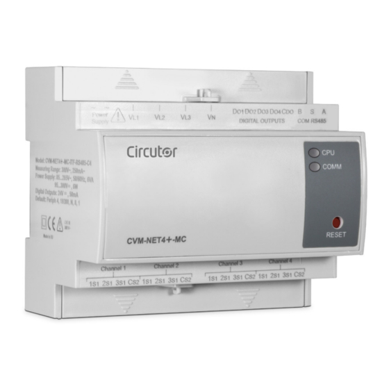
CIRCUTOR's after-sales service. 2.- PRODUCT DESCRIPTION CVM-NET4+-MC is an instrument that measures and calculates the main electrical parameters of three-phase (balanced or unbalanced) and single-phase industrial power networks. It measures effective (RMS) values, using three alternating and neutral voltage inputs and can measure up to 4 circuits with three current inputs (through current transformers In / 0.250 A) . -
Page 7: 3�- Device Installation
The CVM-NET4+-MC device must be installed by authorised and qualified personnel. The power supply plug must be disconnected and measuring systems switched off before handling, al- tering the connections or replacing the device. -
Page 8: 3�3�- Unit Terminals
CVM-NET4+-MC 3�3�- DEVICE TERMINALS Table 3:List of CVM-NET4+-MC terminals Device terminals 1: Auxiliary Power Supply 16: 2 Channel 1 current input s 1, 2: Auxiliary Power Supply 17: 3 Channel 1 current input s 1, 3: V 18: C L1 voltage input... -
Page 9: 3�4�- Connection Diagrams
CVM-NET4+-MC 3�4�- CONNECTION DIAGRAMS 3�4�1�- 3 THREE-PHASE CHANNELS AND 3 SINGLE PHASE CHANNELS Power Supply DIGITAL OUTPUTS COM RS485 COMM RESET Channel 1 Channel 2 Channel 3 Channel 4 Figure 2: 3 three-phase channels and 3 single phase channels Instruction Manual... -
Page 10: 3�4�2�- 4 Three-Phase Channels With Mc1 And Mc3
CVM-NET4+-MC 3�4�2�- 4 THREE-PHASE CHANNELS WITH MC1 and MC3 Power Supply DIGITAL OUTPUTS COM RS485 COMM RESET Channel 1 Channel 2 Channel 3 Channel 4 Figure 3: 4 three-phase channels with MC1 and MC3 Instruction Manual... -
Page 11: 4�- Operation
The parameters that are measured and calculated are shown in: Table 22 Table 23 Table 24 4�1�- KEYBOARD CVM-NET4+-MC has a single button: RESET, used to restore the device's default communication pa- rameters. 4�2�- LEDs The device features 2 LEDs: -CPU, indicates that the device is powered up�... -
Page 12: 4�3�- Digital Output
4�4�- CONFIGURATION As the device has no keypad, the setup parameters must be sent to the device via Modbus/RTU© commands, or using the CIRCUTOR PowerStudio Software, which can be downloaded for free from the web site www.circutor.es. All MODBUS map addresses are hexadecimal. -
Page 13: 4�4�2�- Configuration Of The Transformation Ratios
RX: Time Out 4�4�2�- CONFIGURATION OF THE TRANSFORMATION RATIOS The CVM-NET4+-MC can perform indirect measurements (using voltage and current transformers). For this reason, it has an input table to set the voltage and current transformation ratio configuration. If the voltage measurement is performed directly, the ratio is 1/1. - Page 14 CVM-NET4+-MC Table 7 (Cont�) : Configuration of Channel 2��� 4 transformation ratios Channel 2��� 4 transformation ratios Modbus Variable Valid data margin Address 0 to 7530 (30000) 2B34 Primary of Channel 3 1S1 Single-phase 2B35 Primary of Channel 3 2S1 Single-phase...
-
Page 15: 4�4�3�- Configuration Of Maximum Demand
CVM-NET4+-MC 4�4�3�- CONFIGURATION OF MAXIMUM DEMAND The CVM-NET4+-MC can calculate the maximum demand using the scrolling or fixed window method, depending on the selection. The maximum demand is simultaneously calculated in kW, kVA, A and phase current. Table 9:Maximum demand configuration... -
Page 16: 4�4�5�- Resetting The Maximum Demand
CVM-NET4+-MC 4�4�5�- RESETTING THE MAXIMUM DEMAND When the maximum demand is calculated on the static window, its parameter can be reset, allowing the calculation to be restarted. Table 10:Resetting the maximum demand Modbus Address Variable Data margin 0839 Maximum Demand – Channel 1 083 A Maximum Demand –... -
Page 17: 4�4�8�- Configuration And Use Of Digital Outputs
CVM-NET4+-MC Table 12 (Cont�): Deleting energies Modbus Address Variable Data margin 089B Deleting Channel 2- 1S1 Single phase Energies 089C Deleting Channel 2- 2S1 Single phase Energies 089D Deleting Channel 2- 3S1 Single phase Energies 089E Deleting Channel 3- 1S1 Single phase Energies... - Page 18 CVM-NET4+-MC 4�4�8�3�- Configuration of digital outputs Digital outputs, in addition to being remotely managed, can be used as alarm elements, associated with an electric variable by a maximum or minimum value, or can carry out the power impulse function associated with any power consumption parameter (active or reactive).
-
Page 19: 4�4�9�- Configuration Of Acquisition Channels
0 to 270F (9999 Decimal) 4�4�9�- CONFIGURATION OF ACQUISITION CHANNELS The CVM-NET4+-MC can configure the 3 current inputs of its 4 channels as three-phase or single phase. If configured as three-phase, the currents will be automatically associated with the voltages, as fol- lows: 1S1 to VL1, 2S1 to VL2 and 3S1 to VL3. - Page 20 CVM-NET4+-MC Table 19:Modbus Address 0BC3� Configuration of Channels 3 and 4 Modbus Address 0BC3� Configuration of Channels 3 and 4 Bit 15 Bit 14 Bit 13 Bit 12 Bit 11 Bit 10 Bit 9 Bit 8 Bit 7 Bit 6...
-
Page 21: 4�5�- Modbus Communications
CVM-NET4+-MC 4�5�- MODBUS COMMUNICATIONS One or several CVM-NET4+-MC analyzers can be connected to a computer or PLC. This system makes it possible to centralise the data in a single record point, in addition to the normal operation of each of them (PowerStudio®... -
Page 22: 4�5�1�- Modbus Memory Map
CVM-NET4+-MC 4�5�1�- MODBUS MEMORY MAP 4�5�1�1�- Instantaneous and energy electric variables Table 22:Instantaneous and energy electric variables (Table 1) MODBUS VARIABLES SYMBOL CODE INSTANTANEOUS MAXIMUM MINIMUM UNITS HEXADECIMAL RECORDS Phase voltage 0000-0001 0144-0145 0248-0249 V x10 Phase voltage 0002-0003 0146-0147... - Page 23 CVM-NET4+-MC Table 22 (Cont�) : Instantaneous and energy electric variables (Table 1) MODBUS VARIABLES SYMBOL CODE INSTANTANEOUS MAXIMUM MINIMUM UNITS HEXADECIMAL RECORDS Inductive energy generated kvarLhIII (-) 005A-005B W•h Capacitive energy generated kvarChIII (-) 005C-005D W•h Apparent energy generated kVAhIII (-) 005E-005F W•h...
- Page 24 CVM-NET4+-MC Table 22 (Cont�) : Instantaneous and energy electric variables (Table 1) MODBUS VARIABLES SYMBOL CODE INSTANTANEOUS MAXIMUM MINIMUM UNITS HEXADECIMAL RECORDS Reactive power kvar2 00BA-00BB 01DE-01DF 02CA-02CB Apparent power kVA 2 00BC-00BD 01E0-01E1 02CC-02CD Power factor PF 2 00BE-00BF...
- Page 25 CVM-NET4+-MC Table 22 (Cont�) : Instantaneous and energy electric variables (Table 1) MODBUS VARIABLES SYMBOL CODE INSTANTANEOUS MAXIMUM MINIMUM UNITS HEXADECIMAL RECORDS Three-phase capacitive power kvarC III 011A-011B 022E-022F 030E-030F Apparent three-phase power kVAIII 011C-011D 0230-0231 0310-0311 Three-phase cos φ...
- Page 26 CVM-NET4+-MC Table 23 (Cont�) : Instantaneous electric and energy variables (Table 2) MODBUS VARIABLES SYMBOL CODE INSTANTANEOUS UNITS HEXADECIMAL RECORDS Apparent energy generated kVAh 3 (-) 034A-034B W•h Active energy kWh1 034C-034D W•h Inductive reactive energy kvarhL 1 034E-034F W•h...
- Page 27 CVM-NET4+-MC Table 23 (Cont�) : Instantaneous electric and energy variables (Table 2) MODBUS VARIABLES SYMBOL CODE INSTANTANEOUS UNITS HEXADECIMAL RECORDS Active energy kWh1 03AC-03AD W•h Inductive reactive energy kvarhL 1 03AE-03AF W•h Capacitive reactive energy kvarhC 1 03B0-03B1 W•h Three-phase apparent energy...
- Page 28 CVM-NET4+-MC Table 24 (Cont�) : Voltage and current harmonics MODBUS VARIABLES L1 VOLTAGE / L2 VOLTAGE / L3 VOLTAGE / SYMBOL UNITS HEXADECIMAL RECORDS 1S1 CURRENT 2S1 CURRENT 3S1 CURRENT Base THDA % 0A58-0A59 0A68-0A69 0A78-0A79 mA x10 Harmonic 2 in current...
- Page 29 CVM-NET4+-MC Table 24 (Cont�) : Voltage and current harmonics MODBUS VARIABLES L1 VOLTAGE / L2 VOLTAGE / L3 VOLTAGE / SYMBOL UNITS HEXADECIMAL RECORDS 1S1 CURRENT 2S1 CURRENT 3S1 CURRENT Base THDA % 0AE8-0AE9 0AF8-0AF9 0B08-0B09 mA x10 Harmonic 2 in current...
-
Page 30: 5�- Technical Features
CVM-NET4+-MC 5.- TECHNICAL FEATURES AC Power supply Rated voltage 85 ... 265 V ~ Frequency 50 ... 60 Hz Consumption 2.9...6 VA Installation category CAT III 300 V DC Power supply Rated voltage 95 ...300 V Consumption 3 ... 6 W... - Page 31 CVM-NET4+-MC Environmental features Operating temperature -10ºC... +50ºC Storage temperature -10ºC ... +60ºC Relative humidity (with no condensation) 5 ... 95% Maximum altitude 2,000 m IP31 Protection degree Front panel: IP51 Mechanical features Dimensions (Figure 7) 105x70x90 mm Weight 250 g...
- Page 32 CVM-NET4+-MC Figure 7:CVM-NET4+-MC dimensions Instruction Manual...
-
Page 33: 6�- Maintenance And Technical Service
CVM-NET4+-MC 6.- MAINTENANCE AND TECHNICAL SERVICE In the case of any query in relation to device operation or malfunction, please contact the CIRCUTOR, SA Technical Support Service. Technical Assistance Service Vial Sant Jordi, s/n, 08232 - Viladecavalls (Barcelona) Tel: 902 449 459 ( España) / +34 937 452 919 (outside of Spain) email: sat@circutor.com... -
Page 34: 8�- Ce Certificate
CVM-NET4+-MC 8.- CE CERTIFICATE Instruction Manual... - Page 35 CVM-NET4+-MC Instruction Manual...
- Page 36 CVM-NET4+-MC Instruction Manual...
- Page 37 CVM-NET4+-MC Instruction Manual...
- Page 38 CIRCUTOR, SA Vial Sant Jordi, s/n 08232 -Viladecavalls (Barcelona) Tel.: (+34) 93 745 29 00 - Fax: (+34) 93 745 29 14 www.circutor.es central@circutor.es...
Need help?
Do you have a question about the CVM-NET4+-MC and is the answer not in the manual?
Questions and answers