Table of Contents
Advertisement
Quick Links
CVMk2
NETWORK ANALYZERS CVMk2
The CVMk2 is an instrument which measures, calculates and displays the main
electrical parameters for three-phase industrial systems (balanced or unbalanced).
Measurements are in true effective value, via three AC voltage inputs and three
AC. current inputs. (via IN /5A or IN /1A current transformers). The parameters
measured and calculated are shown in the variables table..
This manual is a quick guide to the use and operation of the CVMk2. For more
information, the whole manual may be downloaded from CIRCUTOR's web
page: www.circutor.es
Before any maintenance, modification to the connections,
repair, etc., the equipment must be disconnected from the
supply. If any operation or protection fault is suspected the
equipment must remain out of service ensuring against any
accidental reconnection. The equipment is designed to be
changed quickly in the event of any breakdown.
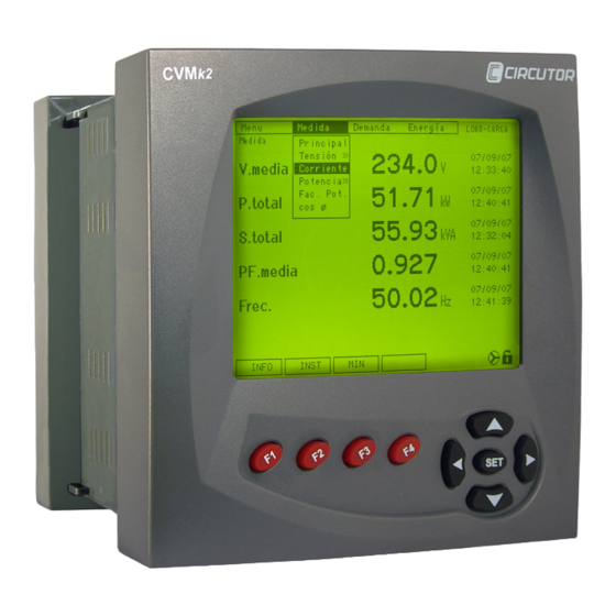
1 DISPLAY DESCRIPTION.
The display can show the values, measured, calculated and stored by the
measuring modules. Display has the screen, the function buttons and movement
buttons.
MENUS
DISPLAY
FUNCTIONS
FUNCTION BUTTONS
MOVEMENT BUTTONS
•
Function buttons: Are identified with F1, F2, F3, F4 and serve to select the
function that appears in the low part of the display.
•
Movement buttons: They serve to move through the upper menu, into the setup
screen and graphic screen.
To move through the options menu and select the wished options, use the
movement buttons and press SET. The selected options, always appears in black
bottom.
2 DISPLAY SETTINGS.
In this group of menus, you will be able to set all the parameters related to the
display.
M98206401-03-13A
Page 1 / 2
2.1
Display options
MENU → SYSTEM → PREFEREN. → DISPLAY
Here you will find all the options related to display's options.
•
Contrast: In this menu you can set the contrast in order to obtain a correct
visualization.
•
LCD OFF: It's possible to switch off automatically the display. Option YES, the
display will switch off at the same time with the backlight. Option NO means that
the display never will switch off.
•
Backlight: To connect or disconnect the backlight, option NO disconnects
permanently the backlight, option YES, switch on permanently the backlight, the
others (20-90-180) are the seconds that will wait the backlight to switch off.
•
Language: allows to set the language device.
2.2
Clock
MENU → SYSTEM → PREFEREN → CLOCK
This screen allows to set the date and time of the device.
•
Time: Allows to set the time of device, the hour format will we always of 24h.
•
Date Type: Allows to set the date format in DD/MM/AA (day / month / year) or
MM/DD/AA, (month / day / year)
•
Date: Allows to set the actual date, the format will be the same that you edited
into the previous option.
2.3
Security
MENU → SYSTEM → PREFEREN → SECURITY
In this screen, you can set the preferences to block the access to unauthorized
persons into setup screens.
•
Lock: The option YES set a password blocking, that only allows to change the
configuration to the authorized persons.
•
Password: In case the a lock is set, you will need to introduce here the current
password. The default password is 1234.
•
New: If you want to change the password for a new one, you will need to set
here the new value.
•
Repeat: This field assures the correct introduction of the password. The
introduced value must be equal than the introduced one in the previous option.
2.4
Device
MENU → SYSTEM → TOOLS → DEVICE
•
Reset: Makes a complete RESET of the equipment, the same function than take
off the power supply.
•
UPDATE: This option set the device in BOOT mode, that allows to update the
device.
•
Baud disp.: Display communicates with the measuring modules through a
RS485 network. Longs networks or with many devices, may be necessary to
reduce the baud rate for good communications.
2.5
Connected measuring modules list
MENU → SYSTEM → MODULES
In this screen you will see the different measuring modules connected to the
display.
3 BASIC
SETTINGS
FOR
MEASURING
MODULES.
The CVMk2 makes the measurement of multiple electric parameters., then we
have to form different options of the device. This quick guide only tells the
necessary to configure correctly.
3.1
Transformer relation
MENU → CONFIG → MEASURE → TRAN. REL
In this menu, we accede to the programming the primary and secondary relation of
the voltage and current ratios.
•
Prim. V: Allows programming the primary of voltage transformer. In case that
transformer is not used, you should program "1".
•
Sec. V: Allows programming the secondary of voltage transformer. In case that
transformer is not used you should program "1".
•
Prim. I: Allows programming the primary value of current transformer.
•
Sec. I: Allows programming the secondary value of current transformer, the
programmable values are... /5 or... /1.
3.2
Quality
MENU → CONFIG → MEASURE → QUALITY
•
THD Calc.: Allows to set the THD calculation using the fundamental wave or the
RMS value.
3.3
Demand
MENU → CONFIG → MEASURE → DEMAND
The CVMk2 calculates the maximum demand of the following values, triphasic
active power, triphasic apparent power, intensity of the three phases and also the
triphasic one. Different aspects for the calculation of the demand can be set, and
are the following ones.
•
Period: It's the time, in minutes, of maximeter function integration, can bet set
from a minimum value of 1 minute and a maximum of 60.
•
Window: Three types of window for demand calculation can be established,
FIXED, SLIDING, THERMAL
•
Syncro: Synchronism, the calculations of demand can be synchronized using an
input of external impulses or by means of synchronization with an internal clock
of equipment, an option selecting EXTERNAL or CLOCK can be chosen
respectively.
•
Input num: In the case that you had selected an impulse for external
synchronism in the previous section, in this point you should indicate which input
will receive the synchronism impulse.
3.4
Tariff
MENU → CONFIG → MEASURE → TARIFF
The CVMk2 allows the configuration of tariffs for the use of for example, energy
meters.
•
Tariff Num: Specifies how many different tariffs will be set.
•
Calendar: Specifies if the CVMk2 uses the internal clock to manage the tariffs,
(option CLOCK) or uses the inputs for it, (the impulse to change the tariffs would
make another external equipment like for example a meter) EXTERNAL option.
•
Input num: If you selected in CALENDAR, an external management of tariffs, in
this point you should specify the input that will receive the impulse.
3.5
Clear
MENU → CONFIG → MEASURE → CLEAR
This screen allows delete the following values:
•
All: All stored values.
•
Maximums: Maximum values, dates and hours.
•
Minimums: Minimum values, dates and hours
•
Energy: Energy and Tariff accountants.
•
Demand: The values of Maxima demand, including those of tariff.
•
Ext. Count: The values of the input's impulses.
3.6
Comm
MENU → CONFIG → COMM → COMM
To program the communication's parameters of measurement modules. If you
want to use a network RS-485, The parameters to program are:
•
Periph num: It is the number of peripheral you want to use.
•
Baud: Baud rate or communication speed that you will use.
•
Parity: The parity used in the communications (NO-ODD-EVEN).
•
Data bit: Numbers of data bits in the frame.
•
Stop bit: Stop bits 1 - 2
•
Protocol: MODBUS protocol.
4 TECHNICAL FEATURES
Product to be protected by an external fuse, model KTK-1 by Bussmann, or similar,
rated 600V, 1A.
Power supply circuit:
Single-phase:
85...265 Vac / 100...300 Vcc.
CD model: 24VDC
Voltage tolerance:
-15 % / +10 %
Frequency:
50 ~ 60 Hz
Maximum consumption:
30 VA, 25W
Operating temperature:
-10ºC .....+ 50 º C
Humidity (without condensation):
5% ..... 95%
Maximum altitude
2.000 m
Mechanical features:
Casing material:
Self extinguishing V0 plastic
Protection:
Assembled
equipment
(DISPLAY):
IP 51
Non assembled equipment (MEASURING
IP 31
MODULE):
For use on a Flat Surface of a Type 1 Enclosure (only for the display module)
Measure module dimensions (mm):
144 x 144 x 70 mm
Screen dimensions (mm):
144 x 144 x 45 mm
Weight:
0.750 kg
Supply and voltage measure wires
minimum section 1 mm²
Secondary C. transformers wires
minimum section 2,5 mm²
Field Wiring terminals to use Copper Conductors only, wire size AWG 14,
minimum temperature rating 60º
Accuracy class:
405 MODEL
402 MODEL
Voltage:
0,5 % ± 1 digit
0,2 % ± 1 digit
Current :
0,5 % ± 1 digit
0,2 % ± 1 digit
Power / Energy:
0,5 % ± 1 digit
0,2 % ± 1 digit
Power factor:
0.5...1
Scale range measurement margin:
0,4%...120% / 0.2%...120%
Measurement circuit:
Rated voltage:
300 Vac Ph-n / 520 Vac Ph-ph
Frequency:
45...65 Hz
Rated current:
In/ 5 A or In/ 1 A.
Permanent overload:
1.2 In
Power consumption voltage circuit:
0.5 VA
Power consumption current circuit
ITF / Shunt
0.9 VA / 0,75 VA
Safety:
Category III - 300 V AC. / 520 AC. EN-61010 Class II double isolation against
electric shock
Standards:
IEC 664, VDE 0110, UL 94, IEC 801, IEC 348, IEC 571-1, EN 61000-6-3,
EN 61000-6-1, EN 61010-1, EN 61000-4-11, EN 61000-4-2, EN 61000-4-3,
EN 61000-4-4, EN 61000-4-5, EN 55011
5 TECHNICAL SERVICE
In case of any equipment failure or any operational queries please contact the
technical service of CIRCUTOR S.A.
TECHNICAL ASSITANCE SERVICE (TAS): (+34) 902449459.
CIRCUTOR S.A. - After sales service
Vial Sant Jordi, s/n
08232 -Viladecavalls (Barcelona)
Tel.: (+34) 93 745 29 00
Fax: (+34) 93 745 29 14
e-mail: central@circutor.es
Advertisement
Table of Contents

Related Manuals for Circutor CVMk2


Summary of Contents for Circutor CVMk2
- Page 1 50 ~ 60 Hz Maximum consumption: 30 VA, 25W This manual is a quick guide to the use and operation of the CVMk2. For more Operating temperature: -10ºC …..+ 50 º C information, the whole manual may be downloaded from CIRCUTOR's web Humidity (without condensation): 5% …..
- Page 2 CVMk2 Page 2 / 2 M98206401-03-13A...
Need help?
Do you have a question about the CVMk2 and is the answer not in the manual?
Questions and answers