Table of Contents

Related Manuals for Check-line CTM2


Summary of Contents for Check-line CTM2
- Page 1 CHECK LINE ® • BY ELECTROMATIC CTM2 - Quick Check Cable Tension Meter Distributed by: ABQ Industrial LP USA Tel: +1 (281) 516-9292 / (888) 275-5772 eFax: +1 (866) 234-0451 Web: https://www.abqindustrial.net E-mail: info@abqindustrial.net...
- Page 2 Dillon is part of Avery Weigh-Tronix. Avery Weigh-Tronix is a trademark of the Illinois Tool Works group of companies whose ultimate parent company is Illinois Tool Works Inc ("Illinois Tool Works"). Copyright © 2014 Illinois Tool Works. All rights reserved. No part of this publication may be reproduced by making a facsimile copy, by the making of a copy in three dimensions of a two-dimensional work and the making of a copy in two dimensions of a three-dimensional work, stored in any medium by electronic means, or transmitted in any form or by any means, including electronic, mechanical, broadcasting, recording or otherwise without the prior written consent of the...
- Page 3 Table of Contents Chapter 1 General Information and Warnings ..................5 About this Manual ......................5 Text Conventions ......................5 Special Messages ....................... 5 Safe Handling of Equipment with Batteries ..............6 Routine Maintenance ......................6 Cleaning the Machine ......................6 Training ..........................
- Page 4 Quick Check Red User Instructions...
-
Page 5: Chapter 1 General Information And Warnings
General Information and Warnings 1.1 About this Manual This manual is divided into chapters by the chapter number and the large text at the top of a page. Subsections are labeled as shown by the 1 and 1.1 headings shown above. The names of the chapter and the next subsection level appear at the top of alternating pages of the manual to remind you of where you are in the manual. -
Page 6: Safe Handling Of Equipment With Batteries
1.1.3 Safe Handling of Equipment with Batteries CAUTION: Danger of explosion if battery is incorrectly replaced. Replace only with the same or equivalent type recommended by the manufacturer. Dispose of used batteries according to the manufacturer’s instructions. ATTENTION: Il y a danger d'explosion s'il y a remplacement incorrect de la batterie, remplacer uniquement avec une batterie du même type ou d'un type équivalent recommandé... -
Page 7: Fcc And Emc Declarations Of Compliance
1.6 FCC and EMC Declarations of Compliance United States This equipment has been tested and found to comply with the limits for a Class A digital device, pursuant to Part 15 of the FCC Rules. These limits are designed to provide reasonable protection against harmful interference when the equipment is operated in a commercial environment. -
Page 8: Declaration Of Conformity (Quick Check Red)
1.7 Declaration of Conformity (Quick Check Red) Quick-Check Red User Instructions... -
Page 9: Declaration Of Conformity (Edx Psu)
1.8 Declaration of Conformity (EDX PSU) Quick-Check Red User Instructions... -
Page 10: Chapter 2 Introduction
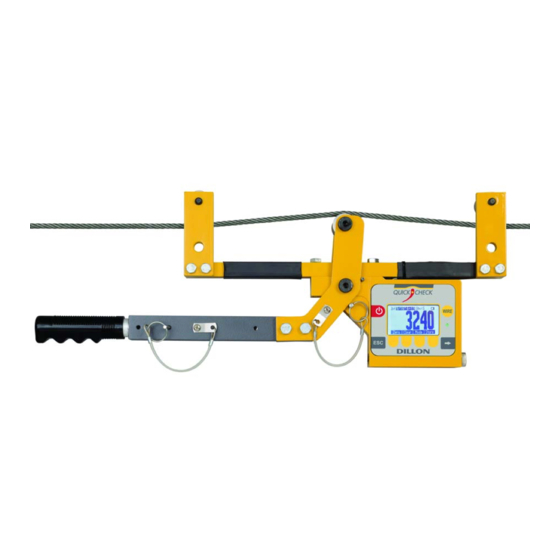
Introduction This manual covers the setup and operation of the Quick-Check Clamp Line Tensiometer from Dillon. The Quick-Check is a simple, accurate strand dynamometer. It is can be clamped onto a cable, accurately determine the wire tension and be removed in seconds. The Quick-Check can handle multiple wire diameters, it can display live tension, dual live/peak tension, average tension captured from several tests, and a check-tensioning graphical display. -
Page 11: Front Panel And Keys
2.2 Front Panel and Keys The front panel of the Quick-Check is shown in Figure 2.2. The light located under the WIRE button illuminates green when changes in the menu are stored, purple when in diagnostics or uploading firmware and red when powering the unit down. Figure 2.2 Quick-Check Front Panel Following are descriptions of the keys and their functions: ON/OFF key. -
Page 12: Important Features
2.3 Important Features Quick to use Attaches and removes from tensioned line in seconds. Quick-tensioning readout for ultra fast line tensioning. Direct tension readings No more complicated lookup charts! Save time and improve accuracy. Portable & rugged Designed for outdoor use. ®... -
Page 13: External Power Supply
2.4.2 External Power Supply Plug the 4-pin end of the power supply cable into the Quick Check 4-pin connector located on the side of the unit. Plug the power supply adapter into an AC power outlet. Refer to Figure 2.4 for a photo of the external power supply. -
Page 14: Chapter 3 Operation
Operation Typical operation of the Quick-Check is covered below, followed by explanations of the various display modes, how to change wire size, how to change the unit of measure, etc. 3.1 Typical Operation To perform a typical tension measurement, see the note below and follow these steps: Take readings at three different places along the cable, moving the tension meter at least four inches for each reading. -
Page 15: Measurement Practices
Release the lever arm and you are ready to perform another measurement. Figure 3.2 Quick-Check Attached to Cable 3.2 Measurement Practices For best measurement, install the Quick-Check at least 2 feet (0.6 m) from terminations, clamps or other hardware. Do not install over the top of wire wrappings. Take readings at three different places along the cable, moving the tension meter at least four inches for each reading. -
Page 16: Softkey Functions
Insure sheaves installed agree with sheaves noted in the Wire calibration. Exception: Sheaves match the wire diameter of the cable to be measured and alternate calibration is selected as per section 5.2. The Quick-Check has an internal temperature sensor inside the electronics cavity. Dramatic temperature changes (such as moving from a warm vehicle to cooler outdoors) requires time for the sensor to reach the same temperature. - Page 17 Mode Press the Mode key to scroll through the four display modes. These are explained below: Live Tension Mode: The display shows the live tension. Dual Peak Mode: The display shows the live tension on the top display and the peak force achieved on the bottom display.
- Page 18 Store Press the Store softkey to store and add a displayed tension to the average of other entered readings. Follow the onscreen prompts. When Multi Leg/Wire is enabled in Log>Setup menu, each leg is identified by a letter rather than a number (A - I). Each tension wire (guy wire) is identified by a number. When the Store softkey is pressed, leg with be displayed.
- Page 19 Note: All Log Modes will record Date and Time along with it's force and peak reading. Setup: Setup allows the user to configure how the Quick Check stores data internally. This stored data can be downloaded via the 4 pin Lemo to a PC via a keyboard wedge or other device.
- Page 20 Comm Port: This allows you to choose where to export the "ON PRINT" logged data. Cell = Setup Cell for data export (4 pin Lemo) Com1 = Not used RADIO = Future development Disabled = to turn off Timed: This is used when the operator wants to record a live load/pull and store it internally.
- Page 21 Comm Port: This allows you to choose where to export the "ON PRINT" logged data. Cell = Setup Cell for data export (4 pin Lemo) Com1 = Not used RADIO = Future development Disabled = to turn off Multi Leg / Wire: This is used to measure tension on tower guyed wires. The readings can be stored (refer to page 18).
- Page 22 The data will be exported to a computer via RS-232. Dillon recommends using “WedgeLink” software as a keyboard wedge. The data needs to be comma delimited and can be exported to an Excel spreadsheet. Refer to Figure for an example. Figure 3.6 Example of Tower Data An operater can key in either a User ID number or a Lift ID assigned to a particular product.
- Page 23 Setup Press the Setup softkey and you will see these choices; Power, PtFmt, Misc, About, Test and Clock. These are described below: Setup Power PtFmt Misc. About Test Clock Choose default Batt Disp Keys Comm Setpts print format: 1 - 5 Peak Capture Rate: (100Hz –...
- Page 24 Enable Auto-Shutdown - Auto-Shutdown powers off the instrument automatically. If Yes is chosen, the following options will be displayed: Shutdown Timer (Min): Program to shut down after a period of inactivity. Shutdown Type: Select a method of shutdown. Fixed: Set the amount of time for the unit to shut off No Load: No load of the tension meter No Change: No change in weight PtFmt:...
- Page 25 About: Press this softkey to see the following information: Device - Press this softkey to show a list of information about the Quick- Check; serial number, capacity rating, hardware and software revision levels. Press any key to return to the previous softkey set. Calib - Press this softkey to show Calibration Points and the calibration information for the current wire size.
-
Page 26: Chapter 4 Configuration Mode
Configuration Mode 4.1 Accessing the Configuration Mode You need to access the Configuration mode to perform certain tasks. Access to some of these tasks may be restricted by a supervisor password. To access Configuration mode: From normal operating mode, press the Right Arrow softkey… A new softkey set, shown below, appears: Shv:S 7/16 6X19... - Page 27 The unit is now in the Configuration mode. To see the rest of the softkeys available in this mode, press the Right Arrow key. All the Config softkeys are shown below. The softkeys in the Configuration mode are Wire, Setup, Reso, Comm, Mode, Units, Power, ChPwd, and Reset.
- Page 28 Comm Communication output (COM1) and RADIO are not supported at this time in the Quick- Check. Press the COMM key to select Cell. Cell - Press this key to configure the RS-232 port (4 pin Lemo) COM1 - Not used RADIO - For specials and future development Mode Press this softkey to set the display mode on power up.
- Page 29 Fixed - The unit will shutdown after the set number of minutes no matter what happens. No Load - The unit will shutdown after the set number of minutes only if there is no load on the unit. This prevents shutdown in the middle of line tensioning.
-
Page 30: Chapter 5 Changing Sheaves
Changing Sheaves Do not use the Quick-Check with cable larger than indicated on the sheaves. Overload and damage to the instrument may result. Do not mix sheave sizes. This will result in inaccurate measurement and possible overload. As you use the Quick-Check on different diameter cables you must change to the correct sheave size. -
Page 31: Chapter 6 Achieving Best Accuracy
Achieving Best Accuracy 6.1 Accuracy The Quick-Check is an instrument designed to give accuracy that typically exceeds normal requirements for wire tensioning. You should have an understanding of what factors affect tension measurement accuracy. 6.2 Calibration to Specific Wire Type While it is best to have the instrument calibrated to the specific wire size(s) and type(s) used, the Quick-check can often work adequately in other situations. -
Page 32: Non-Linearity
6.5 Non-linearity Most three-point tension meters employ only linear characterization and have large errors at the midpoints (up to 15%). The Quick check uses multi-point segmenting to correct for non-linearity, reducing it to less than 0.2%. 6.6 Wire Characteristics Creep Every material including steel exhibits creep under load. -
Page 33: Chapter 7 Troubleshooting
Troubleshooting 7.1 Quick Check Problem Possible Cause Solution Powers on momentarily and turns off Low battery Replace with high quality alkaline batteries Bad keypad Have unit serviced Does not power on Low battery Replace with high quality alkaline batteries Batteries installed Insure that positive terminals of both batteries (nub) face backwards or no spring inward –... - Page 34 7.2 EDX PSU Problem Possible Cause Solution Quick Check powers on Low battery Replace with high quality alkaline batteries. Do not use rechargeable momentarily and turns off batteries. Bad keypad Have unit serviced. Quick Check does not power Low battery Replace with high quality alkaline batteries.
-
Page 35: Chapter 8 Specifications
Specifications Power 2 AA, common alkaline batteries. Display Dot graphic LCD display Operational Keys Power, Wire, Escape/Clear (ESC), Next ( ) and four softkeys with changing function and label, depending on the specific menu in use Operational Annunciators Unit of measure, battery level Display Resolution 2,000 lbf/ 10 kN/ 1000 kgf Quick-Check instrument: Displayed resolution setting... -
Page 36: Edx Psu Power Supply Specifications
Available Options Varied wire sizes Operating Environment Suitable for outdoor use Dimensions 10˝ x 23˝ x 3˝ (25 cm x 59 cm x 8 cm) approximately Weight 11 lb (5 kg) approximately 8.1 EDX PSU Power Supply Specifications Enclosure Designed for indoor use Input Voltage 100-240 VAC 50-60Hz, 0.55A Output Voltage...
Need help?
Do you have a question about the CTM2 and is the answer not in the manual?
Questions and answers