Table of Contents
Advertisement
Advertisement
Table of Contents

Related Manuals for Check-line DTS-200


Summary of Contents for Check-line DTS-200
- Page 1 CHECK •LINE ® BY ELECTROMATIC MODEL DTS DIGITAL TENSION METER Operating Manual...
-
Page 2: Table Of Contents
TABLE OF CONTENTS 1.0 Introduction ......................... 02 2.0 Overview of Operating And Display Elements ............03 3.0 Set-up ........................06 Charging the battery Turning the tension meter ON and OFF 4.0 Tension Meter Settings ....................07 Procedure Setting chart Material menu Password Factory Reset 5.0 Operation ........................ -
Page 3: Introduction
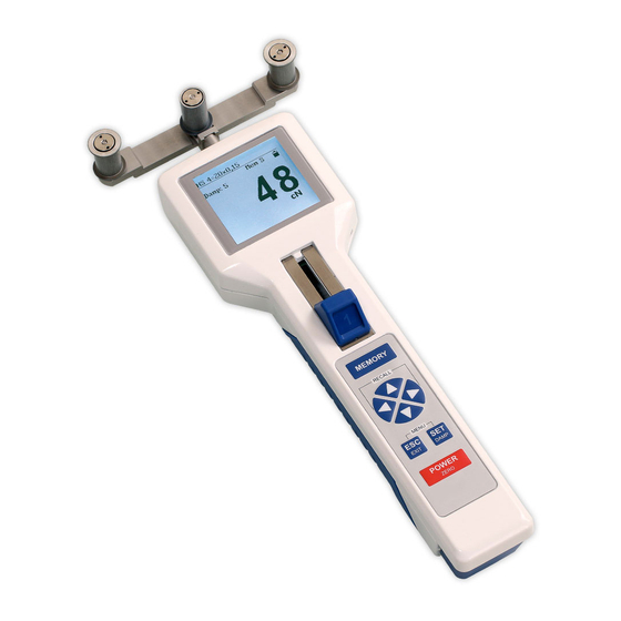
1.0 INTRODUCTION The DTS is supplied as a complete kit that includes: (1) Tension meter with accumulator and AC adapter with country adapters (EU, US, UK) (1) Certificate of compliance with the order 2.1 under EN 10204 (1) Operating Instructions (1) Carrying case NOTE: Unpack the tension meter and inspect it for shipping damage. - Page 4 Numeric display Adjusted material Info on material Battery status indicator diameter Damping Memory mode (data stored in the memory) Current reading Measurement unit MIN/MAX Alarm FIG. 2 Display with Bargraph Adjusted material Info on material Battery status indicator diameter Damping Memory mode (data stored in the memory) Current reading...
- Page 5 Graphic display Adjusted material diameter Battery status indicator Info on material Damping Memory mode (data Tension range stored in the memory) Measured values MAX.-alarm value as graph MIN.-alarm value Current reading Measurement unit MIN/MAX Alarm Alarm values FIG. 4 The Y-axis can be scaled with the buttons.
-
Page 6: Setup
3.0 SETUP The tension meter is delivered with a built-in rechargeable LiPo battery, which has been charged at the factory. The tension meter can only be switched on if the battery is still working, i.e. if the battery has enough charge. If the instrument does not power up or if the battery level indicator shows only one bar after power-up switching the tension meter on, the battery needs to be recharged. -
Page 7: Tension Meter Settings
4.0 TENSION METER SETTINGS Thumbpiece positions Pos. 2 Pos. 0 Pos. 1 FIG. 5 2 = Measurement position 0 = Adjustment position 1 = Threading position (guide rollers in their forward position Menu settings can be changed with the thumbpiece in Pos. - Page 8 Tension Meter settings chart Main Menu Submenu Settings Menu Description Material [1] to [11] Section 4.3 Material set up Cal. — [–10%] – [+10%] Section 5.7 Adjustment [numeric] • Measured value displayed as number and alarm monitoring [Bargraph] • Measured value displayed as number, bar graph trend Display —...
-
Page 9: Material Menu
Material Menu In the material menu you can make the settings for the selected material characteristics and perform the calibration. To perform the calibration, the weights for the selected calibration points must be available. Material Setup Submenu Settings Menu Description No. -
Page 10: Operation
5.0 OPERATION Requirements 1. Switch the tension meter on (Section 3.2) 2. Define the required tension meter settings (Section 4.2) 3. Select the desired material characteristic (Section 4.3) 4. Set the material thickness compensator (Section 5.2), if equipped 5. Bring the tension meter into the desired measuring position and carry out a zero adjustment as described in Section 5.3, if required. -
Page 11: Zero Adjustment Of The Measurement Position
Zero adjustment of the measurement position Each time the measurement position is changed, the tension meter will automatically perform a zero adjustment. If the tension meter does not display zero in its measuring position, perform a manual zero adjustment procedure. For this purpose, no material to be measured must have been inserted yet! Requirements: 1. - Page 12 To insert the material to be measured: 1. Push the thumbpiece in the direction of the arrow into its threading position 1 (1) until the outer guide rollers extend beyond the filament guide. 2. Position the material to be measured into the tension meter in such a way that it contacts the Filament guide and passes between the outer rollers and the middle measuring roller (1) .
-
Page 13: Damping
Numerical Display Display with bargraph Graphical Display FIG. 8 FIG. 9 FIG. 10 6. Press the button simultaneously to change the different display modes during the working mode. Do not let the thumbpiece snap back as this could affect the calibration and damage the instrument. -
Page 14: Alarm Function
The factory setting for the damping factor is 5. The average shown on the display is calculated as follows: 5 old measured values + 4 new measured values Damping can be changed in 9 steps from 01 = low damping: 1 old measured value + 8 new measured values to 9 = high damping: 8 old measured values + 1 new measured value... -
Page 15: Peak Value
3. Press the key to perform the calibration adjustment until the value on thedisplay corresponds to the weight suspended to the material. The adjustment can be performed in 1 % steps within the range from + 10% to –10%. 4. Press the button to save the determined value. -
Page 16: Creating A Material Characteristic
6.0 CREATING A MATERIAL CHARACTERISTIC The tension meter has been calibrated on material 1 according our factory procedure for a vertical material path and cannot be deleted or overwritten. The the materials and diameters are given in Section 2. Factory calibrations using customer supplied materials follow the same procedure. - Page 17 Requirements: 1. The thumbpiece must be in the adjustment position(4) (Fig. 6). 2. The material thickness compensator (if existing) must be set to the adjustment position (Section 5.2) 3. The unit for the material thickness must have been set (Section 4.3) To perform the calibration procedure: 1.
- Page 18 Step 2: Set the diameter This step is only required for tension meters with a material thickness compensator Step 3: Perform a zero adjustment with the tension meter in its measuring position Step 4: Calibrate calibration point 1 Insert material to be measured Step 5: Calibrate calibration point 2 Step 6:...
-
Page 19: Verifying The Calibration
Verifying the calibration When verifying the calibration, make sure to select the same material, calibration position and calibration points as used for creating the associated material characteristic. Otherwise, the precision of the measurements will not be sufficient. The tension meter has been calibrated on material 1 according our factory procedure for a vertical material path and cannot be deleted or overwritten. -
Page 20: Memory Functions
Memory functions You can store and display the statistics of one measuring series (last measured value, the average, the minimum and maximum measured values, the peaks, the standard deviation). Data is recorded during a user-defined period. Save data 1. Press the button to start recording the measured values. -
Page 21: Specifications
7.0 SPECIFICATIONS General Specifications Calibration According factory procedure Accuracy For PA from 5 % up to 100 % full scale: ± 0.5 % full scale ± 1 digit remaining tension range and other calibration materials: ± 3 % FS* ± 1 digit Memory for material curves 1 factory calibration plus 4 for customized calibrations... -
Page 22: Available Models
*Measuring Calibration Thickness Ranges Head Width Matretial 1 Compensator Polyamide [PA] for Included Monofilament DTS-200 0.2 - 200.0 0.12 mm Ø DTS-500 0.5 - 500.0 0.12 + 0.20 mm Ø DTS-1000 10 - 1000 0.20 + 0.40 mm Ø DTS-2000 20 - 2000 0.40 + 0.70 mm Ø... -
Page 23: Guide Rollers
Ceramic-coated aluminium Asymetrical groove 1000 Hard-coated aluminium Code ASY (not for DTS-200) Code ASYB 1000 Tempered steel for measuring tire cord (not for DTS-200) Code V1 1000 Hard-coated aluminium (only for DTS-60K-V1) U-grooved 2000 Hard-coated aluminium(not for Code U DTS-200) -
Page 24: Maintenance And Cleaning
8.0 MAINTENANCE AND CLEANING Maintenance The tension meter is easy to maintain. Depending on operating time and load, the instrument should be checked according to the locally valid regulations and conditions. The use of other test methods than the procedure described in Section 5.0 may cause deviating measuring results. -
Page 25: Warranty
WARRANTY ELECTROMATIC Equipment Co., Inc. (ELECTROMATIC) warrants to the original purchaser that this product is of merchantable quality and confirms in kind and quality with the descriptions and specifications thereof. Product failure or malfunction arising out of any defect in workmanship or material in the product existing at the time of delivery thereof which manifests itself within one year from the sale of such product, shall be remedied by repair or replacement of such product, at ELECTROMATIC’s option, except where unauthorized repair, disassembly, tampering,... - Page 26 ELECTROMATIC CHECK •LINE ® O . , 600 Oakland Ave., Cedarhurst, NY 11516 – USA INSTRUMENTS TEL: 516-295-4300 • FAX: 516-295-4399...
Need help?
Do you have a question about the DTS-200 and is the answer not in the manual?
Questions and answers