
Related Manuals for Check-line TI-25M


Summary of Contents for Check-line TI-25M
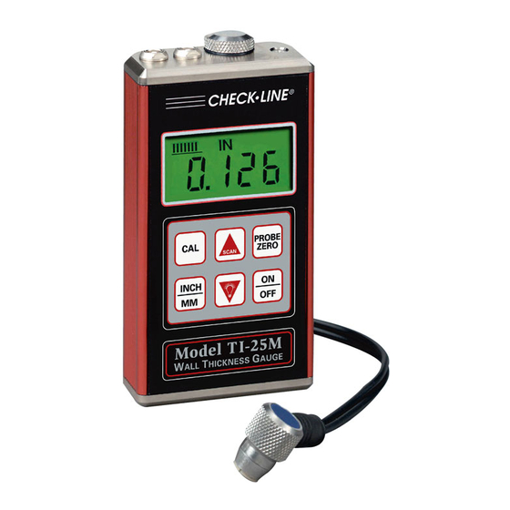
- Page 1 ® CHECK LINE • BY ELECTROMATIC TI-25M LTRASONIC HICKNESS AUGE Operating Instructions...
-
Page 2: Table Of Contents
OI-UT004M ABLE OF ONTENTS Introduction ......... Precautions. -
Page 3: Introduction
The elapsed time for the complete cycle is measured and converted to an accurate thickness reading. The TI-25M can be used to measure the extent of corrosion on the opposite, inaccessible side of the wall by using the “Subtractive Method.” When the... -
Page 4: Overview Of Gauge
3.0 O VERVIEW AUGE 3.1 Gauge Probe Zero Test Plate and Probe Battery Compartment Cover Receptacles Backlit LCD Display Membrane Keypad Probe – 4 –... -
Page 5: Contents Of Kit
The probe transmits and receives the ultrasonic sound waves which the TI-25M uses to calculate the thickness of the material being measured. The probe must be used correctly in order for the TI-25M to produce accurate and reliable results. A small amount of “coupling” fluid, commonly called “couplant” is used to insure that there are no air gaps between the probe and the material surface. -
Page 6: Keypad
3.4 Keypad The TI-25M is supplied with a membrane keypad mounted PROBE ZERO on the front of the instrument body. It consists of six (6) keys, each performing one or more functions as described INCH below. CAL key is used to enter and exit the Tl-25M’s two Calibration modes. -
Page 7: Lcd Display
When a measurement is being performed, six or seven bars should be illuminated indicating that it is a stable measurement. If fewer than five bars are illuminated, the TI-25M is having difficulty obtaining a stable and reliable measurement and the thickness value shown should be ignored, as it is most likely erroneous. -
Page 8: Probe Zeroplate
3.6 Probe ZeroPlate When first connecting the probe supplied with the TI-25M, the user should perform a “Probe Zero” as described in Section 4.3. The Probe Zero Test Plate is used for this task. It is located on the top edge of the gauge as shown in the photo below. -
Page 9: Probe Connector Receptacle
3.7 Probe Connector Receptacle Located on the top edge of the TI-25M housing are the receptacles for the probe and the probe zero plate. The connectors for the probe Probe Zero Plate are non-polarized so the con- Probe Receptacles nector at the end of the probe... -
Page 10: Getting Started
5. While maintaining probe contact with the Test Plate, press the key. The display will show “Prb0” while the TI-25M calculates its zero point. Note: The value shown on the display can be recorded and used in the future to confirm that the gauge is functioning properly. -
Page 11: Changing Units - Inches To Mm
The built-in Probe Zero Plate can also be used whenever desired to confirm that the gauge is working properly. The steel Test Plate will measure 0.250" (6.35) if the TI-25M is calibrated for steel (factory default) or some other value higher or lower depending upon the material type that the gauge is calibrated for. - Page 12 Extremely rough surfaces such as the “pebble-like” finish of some cast irons, will prove most difficult to measure. These kinds of surfaces act on the sound beam like frosted glass acts on light; the beam becomes diffused and scattered in all directions. Rough surfaces also contribute to excessive wear of the probe, especially in applications where the probe is “scrubbed”...
-
Page 13: Quick Start Instructions - Steel Thickness
5.0 QUICK START INSTRUCTIONS — STEEL THICKNESS These Quick Start procedures are intended for those applications where the thick- ness of steel is to be measured. If a material other than steel will be measured, the gauge must be calibrated for use on this particular material. Refer to Sections 6.0 through 8.0 for additional details. - Page 14 TI-25M may perform a measurement that is larger or smaller than it should be. This phenomenon is obvious when one thickness value is observed while the probe is in contact with the material, and another value after the probe is removed.
-
Page 15: Calibration For Measuring Thckness
0.2330 IN/µs (inches-per-microsecond), versus that of aluminum, which is about 0.2500 IN/µs. It is critical that the TI-25M be set for the correct acoustic velocity depending upon the material to be measured. The TI-25M is shipped from the factory calibrated for steel with an acoustic velocity of 0.2330 IN/µs (5920 M/s). -
Page 16: Acoustic Velocity Table
6.1 Acoustic Velocity Table Material Velocity Velocity Equivalent Value Equalvalent Value Type Inches/µs Meters/s Of Test Plate (Inches) Of Test Plate (mm) Aluminum 0.2500 6350 0.269 6.82 Bismuth 0.860 2184 0.085 2.16 Brass 0.1730 4394 0.183 4.66 Cadmium 0.1090 2769 0.111 2.83 Cast Iron... -
Page 17: Changing Calibration - Acoustic Velocity Is Known
Note: If the key is pressed while in the calibration mode, the TI-25M will be reset to the factory default calibration for common steel (0.2330 IN/µs or 5920 M/s). – 17 –... -
Page 18: Changing Calibration - Acoustic Velocity Is Not Known
Note: If the key is pressed while in the calibration mode, the TI-25M will be reset to the factory default calibration for common steel (0.2330 IN/µs or 5920 M/s). – 18 –... -
Page 19: Description Of Measuring Modes
7.0 DESCRIPTION OF MEASURING MODES The TI-25M can be used in either the Single Thickness Reading mode or the Scan mode. The Single Thickness Reading mode is suitable for most applications. While the probe remains in contact with the material being measured, the TI-25M performs four (4) measurements every second, updating the LCD display after each read- ing. -
Page 20: Measuring Procedure
8.0 MEASURING PROCEDURE After setting the TI-25M for the correct acoustic velocity, or retaining the factory-set acoustic velocity for steel, the gauge is ready to take wall thickness measurements. 1. Turn on the power by pressing the key. 2. Plug the probe cable into the receptacle at the top of the gauge. -
Page 21: Measurements Of Pipes Or Cylindrical Parts
6. If two materials are press-fitted or laminated together, the gauge will only measure the thickness of the sample that contacts the probe. 8.2 Measurements Of Pipes Or Cylindrical Parts When using the TI-25M to Perpendicular measure the wall thickness of a pipe, the orientation of the probe is very important to obtain accurate readings. -
Page 22: Measurements On Materials At High Temperatures
8.3 Measurements On Materials At High Temperatures When it is necessary to measure wall thickness on surfaces that are in excess of 200 °F (100 °C), special-purpose high temperature probes should be used. These probes are built using special materials and techniques that allow them to withstand high temperatures without damage. -
Page 23: Specifications
9.0 S PECIFICATIONS 0.60–150.0 mm) Range* 0.025–6.00" ( Other ranges available with optional probes. Resolution .001" (0.01 mm) ⁄ Display -Digit, 0.5" Backlit LCD Velocity Range 6500–33,000 ft./sec. (2000–10,000 m/sec.) 7.5 MHz, 0.25" Diameter (6.35 mm) Probe with rubber molded grip. Probe Wearface PEEK (Polyethylethylkeytone) -
Page 24: Material Safety Data Sheet (Msds)
Respiratory Protection: not required Ventilation: not required Protective Gloves: on individuals demonstrating sensitivity to TI-25M Eye Protection: as required by working conditions Other Protective Equipment: not required 1. TI-25M contains only food grade and cosmetic grade ingredients. – 24 –... -
Page 25: Warranty
11.0 W ARRANTY ELECTROMATIC Equipment Co., Inc. (ELECTROMATIC) warrants to the original purchaser that this product is of merchantable quality and confirms in kind and quality with the descriptions and specifications thereof. Product failure or malfunction arising out of any defect in workmanship or material in the product existing at the time of delivery thereof which manifests itself within one year from the sale of such product, shall be remedied by repair or replacement of such product, at ELECTROMATIC’s option, except where unauthorized repair,...
Need help?
Do you have a question about the TI-25M and is the answer not in the manual?
Questions and answers