Advertisement
Quick Links
11.00 WARRANTY
ELECTROMATIC Equipment Co., Inc. (ELECTROMATIC) warrants to the original pur-
chaser that this product is of merchantable quality and confirms in kind and quality
with the descriptions and specifications thereof. Product failure or malfunction arising
out of any defect in workmanship or material in the product existing at the time of deliv-
ery thereof which manifests itself within one year from the sale of such product, shall be
remedied by repair or replacement of such product, at ELECTROMATIC's option, except
where unauthorized repair, disassembly, tampering, abuse or misapplication has taken
place, as determined by ELECTROMATIC. All returns for warranty or non-warranty
repairs and/or replacement must be authorized by ELECTROMATIC, in advance, with
all repacking and shipping expenses to the address below to be borne by the purchaser.
THE FOREGOING WARRANTY IS IN LIEU OF ALL OTHER WARRANTIES,
EXPRESSED OR IMPLIED, INCLUDING BUT NOT LIMITED TO, THE WARRANTY
OF MERCHANTABILITY AND FITNESS FOR ANY PARTICULAR PURPOSE OR
APPLICATION. ELECTROMATIC SHALL NOT BE RESPONSIBLE NOR LIABLE
FOR ANY CONSEQUENTIAL DAMAGE, OF ANY KIND OR NATURE, RESULTING
FROM THE USE OF SUPPLIED EQUIPMENT, WHETHER SUCH DAMAGE OCCURS
OR IS DISCOVERED BEFORE, UPON OR AFTER REPLACEMENT OR REPAIR, AND
WHETHER OR NOT SUCH DAMAGE IS CAUSED BY MANUFACTURER'S OR SUP-
PLIER'S NEGLIGENCE WITHIN ONE YEAR FROM INVOICE DATE.
Some State jurisdictions or States do not allow the exclusion or limitation of incidental
or consequential damages, so the above limitation may not apply to you. The duration
of any implied warranty, including, without limitation, fitness for any particular purpose
and merchantability with respect to this product, is limited to the duration of the forego-
ing warranty. Some states do not allow limitations on how long an implied warranty
lasts but, not withstanding, this warranty, in the absence of such limitations, shall
extend for one year from the date of invoice.
ELECTROMATIC Equipment Co., Inc.
600 Oakland Ave. Cedarhurst, NY 11516—USA
Tel: 1-800-645-4330/ Tel: 516-295-4300/ Fax: 516-295-4399
32
OI808X
1.00
INTRODUCTION . . . . . . . . . . . . . 2
2.00
DTMX OVERVIEW . . . . . . . . . . . . 3
3.00
DESCRIPTION OF KEYS . . . . . . 4
3.10 Auxiliary Functions
4.00
QUICK START INSTRUCTIONS . 5
4.10 Setup
4.20 Operation
5.00
SETUP . . . . . . . . . . . . . . . . . . . . 8
5.10 Installing Batteries
5.20 AC Adapter
5.30 Configuring Dip Switches
5.31 Access the DIP Switch Block
5.32 Setting the DIP Switches . .
5.40 Material Rigidity Selector
5.50 Thickness Compensator
5.51 Preparing Sample
5.52 Inserting Sample
5.60 Gravity Correction (Zero)
6.00
BUILT-IN MEMORY SYSTEM . . . 14
6.10 Standard Memory
6.11 Viewing Data
6.12 Clearing Data
6.20 Standard NAPO Memory
6.30 On-Demand Data Logging
6.31 Viewing Data
6.32 Clearing data
6.40 Continuous Data Logging
6.41 Viewing Data
6.42 Clearing Data
INDEX
7.00
DOWNLOADING DATA
7.10 Output Cables
7.20 Connector Pinouts
7.30 Analog Output
7.40 Serial Output - Printer
7.41 Signal Characteristics
7.42 Printer Setup Data
7.50 Serial Output - Computer
7.51 Signal Characteristics
7.52 Data Format
8.00
CALIBRATION . . . . . . . . . . . . . . 23
8.10 Checking Calibration
8.20 Field Calibration Adjustment
8.30 Special Calibration
9.00
GENERAL NOTES . . . . . . . . . . . 26
9.10 Turning Power On/OFF
9.20 Display Indicators & Error
Codes
. . . . . . . . . . . . . . . . . . . .
9.21 Over Range Indicator
9.22 Error Codes
9.23 Low Battery
9.30 Standard Dev. & Avg. Formulas
9.40 Changing Units of Measure
9.50 Options
9.51 Ultra-High Speed Rollers . .
9.52 Lever
9.53 Printer
9.54 Serial Output Cable
9.55 Analog Output Cable
9.56 AC Adapter
9.57 Special Calibration
9.60 On-Line Mounting Holes
10.00 SPECIFICATIONS . . . . . . . . . . . . 30
11.00 WARRANTY . . . . . . . . . . . . . . . . 32
. . . . . . . 19
.
. .
1
Advertisement

Related Manuals for Check-line DTMX-200


Summary of Contents for Check-line DTMX-200
- Page 1 OI808X INDEX 11.00 WARRANTY ELECTROMATIC Equipment Co., Inc. (ELECTROMATIC) warrants to the original pur- chaser that this product is of merchantable quality and confirms in kind and quality 1.00 INTRODUCTION ... . . 2 7.00 DOWNLOADING DATA .
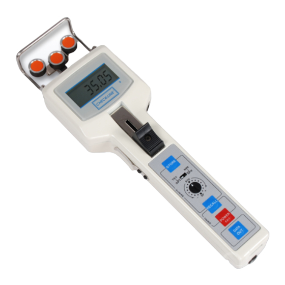
- Page 2 1.00 INTRODUCTION Specifications Measuring Principle Strain gauge The CHECK•LINE ® DTMX Digital Tension Meter is a hand-held device which Measuring Frequency 16 msec (62.5 samples/sec) accurately measures the running as well as static tensions of a wide variety of Deflection of Sensing Roller (max.) 0.2 mm process materials including yarns, fibers, wires, optical fibers, etc.
-
Page 3: Specifications
Clips Compensator (on back of unit) Thumbpiece All dimensions in mm STORE Key Material Rigidity Selector Field Calibration Model Data Adjustment Model DTMX-200 DTMX-500 DTMX-1K DTMX-2K DTMX- 2.5KB DTMX-5KB DTMX-10KB DTMX-20KB Tension Range (grams) 0.1–200.0 0 .1–500.0 50 –1000 200–2000 250–... - Page 4 3.00 DESCRIPTION OF MEMBRANE KEY FUNCTIONS 9.55 Analog Cable The CA cable is for connection to chart Description of Functions recorders or other recording devices. • Starts/Stops scanning for Max/Min/Peak values. (Standard Memory) It is supplied with bare leads for easy STORE •...
-
Page 5: Quick Start Instructions
For line speeds up to 5,000 m/min, specify secure the ends of the sample under the Sample Holding Clips on each side “U” roller guides. of the unit. Thickness Compensator is not used on the DTMX-200 Model. 2. Set the Material Rigidity Selector to "TEX” or "WIRE"... - Page 6 3. Open the 3-roller system by pushing the 9.23 Low Battery Filament Thumbpiece forward until the outer Filament guide When the “B” indicator appears on the rollers extend beyond the filament guide. display, the batteries are low. If data is Thumbpiece Position the DTMX so that the process stored in memory, download it before...
-
Page 7: General Notes
9.00 GENERAL NOTES 6. Press the key repeatedly to RECALL review the data stored in memory. 9.10 Turning Power On/Off POWER Turn Power On: Press EXIT POWER Turn Power Off: Press and hold the EXIT key for five (5) seconds Note: DTMX will power off automatically after 90 seconds of inactivity, except for the following instances:... - Page 8 8.20 Field Calibration Adjustment 5.00 SETUP Factory Calibration The Field Calibration Adjustment permits Battery cover screw 5.10 Installing/Replacing Batteries the end user to "shift" the calibration curve Increase Decrease 1.5% 1.5% to provide better accuracy when the factory 1. Using a slotted screwdriver or coin, per step per step standard calibration is not suitable.
- Page 9 8.10 Checking Calibration 5.20 Using AC-Adapter It is important to check the calibration of the DTMX The optional AC-DTMX AC Adapter can be Vertical Material frequently to insure that the gauge continues to per- used as an alternative to batteries. Plug one Path form within factory specifications.
- Page 10 8.00 CALIBRATION 5.30 Configuring Dip Switches The DTMX is supplied with six (6) dip switches permitting the user to select The DTMX is factory calibrated by taking a series of measurements with desired Display Update Rate, Memory Mode and Data Output Type as detailed known weight standards suspended from Factory Calibration Standard below.
- Page 11 4. The Dip Switch Block will be located 7.51 Signal Characteristics Factory switch: at the top of the opening after DO NOT Signal Baud Rate Word Length Parity Stop Bits EOL Delimiter TOUCH removing the Slide Guide Plate. RS-232C 4800 8-bit None 2-bits...
- Page 12 Compensator. Remote Host Computer Commands (Poll) 2. It is unnecessary to use the Thickness Compensator on the DTMX-200 because the Request Data Point “D” (ASCII capital letter “D") range of material diameters used with this Zero “Z”...
- Page 13 7.20 Output Connector Pin Outs 5.51 Preparing Sample For Thickness Compensator When using monofilament, wire or other difficult- 10-Pin Output Connector 1 RXD to-bend materials, the sample must be prepared arc A 2 TXD RS-232C properly before inserting into the Thickness 3 CTS 4 RTS Compensator.
-
Page 14: Downloading Data
6.00 BUILT-IN MEMORY SYSTEM 7.00 DOWNLOADING DATA The DTMX Built-In Memory system can be configured to operate in one of the When configured for either Continuous Data Logging Memory Mode or On- following modes: Standard Memory, Standard Memory With No Auto Power Demand Data Logging Memory Mode, the recorded data can be downloaded for Off, On-Demand Data Logging and Continuous Data Logging. - Page 15 6.41 Viewing Data In Continuous Data Logging Mode 6.11 Viewing Data In Standard Memory RECALL To view data stored in the Extended Memory press the To view data stored in Standard Memory, press the RECALL key. The following will be displayed when the key is pressed repeatedly.
- Page 16 6.30 On-Demand Data Logging Mode When configured for On-Demand Data Logging Mode, up to 100 data points Maximum Value Minimum Value Average Value Standard Deviation can be stored in memory along with the calculated average and standard deviation of the stored values. Each data point can be manually entered into Data Point 100 Data Point #2 Data Point #1...
- Page 17 CHECK LINE ® • BY ELECTROMATIC Digital ENSION ETER Model DTMX O P E R A T I N G M A N U A L Distributed by: ABQ Industrial LP USA Tel: +1 (281) 516-9292 / (888) 275-5772 eFax: +1 (866) 234-0451 Web: https://www.abqindustrial.net E-mail: info@abqindustrial.net...
Need help?
Do you have a question about the DTMX-200 and is the answer not in the manual?
Questions and answers