Table of Contents
Advertisement
Advertisement
Table of Contents

Subscribe to Our Youtube Channel
Related Manuals for Supermicro X11SPW-CTF


Summary of Contents for Supermicro X11SPW-CTF
- Page 1 X11SPW-CTF X11SPW-TF USER'S MANUAL Revision 1.0...
- Page 2 State of California, USA. The State of California, County of Santa Clara shall be the exclusive venue for the resolution of any such disputes. Supermicro's total liability for all claims will not exceed the price paid for the hardware product.
-
Page 3: About This Manual
Preface About This Manual This manual is written for system integrators, IT technicians and knowledgeable end users. It provides information for the installation and use of the X11SPW-CTF/-TF motherboard. About This Motherboard The Supermicro X11SPW-CTF/-TF supports an Intel® Xeon 81xx/61xx/51xx/41xx/31xx series (Socket P0-LGA 3647) processor with a thermal design power (TDP) of up to 205W. -
Page 4: Contacting Supermicro
X11SPW-CTF/-TF User's Manual Contacting Supermicro Headquarters Address: Super Micro Computer, Inc. 980 Rock Ave. San Jose, CA 95131 U.S.A. Tel: +1 (408) 503-8000 Fax: +1 (408) 503-8008 Email: marketing@supermicro.com (General Information) support@supermicro.com (Technical Support) Website: www.supermicro.com Europe Address: Super Micro Computer B.V. -
Page 5: Table Of Contents
Preface Table of Contents Chapter 1 Introduction 1.1 Checklist ..........................8 Quick Reference .......................12 Quick Reference Table ......................13 Motherboard Features .......................15 1.2 Processor and Chipset Overview ..................19 1.3 Special Features ........................19 Recovery from AC Power Loss ..................19 1.4 System Health Monitoring ....................20 Onboard Voltage Monitors ....................20 Fan Status Monitor with Firmware Control ...............20 Environmental Temperature Control .................20... - Page 6 X11SPW-CTF/-TF User's Manual 2.3 Motherboard Installation .....................31 Tools Needed ........................31 Location of Mounting Holes ....................31 Installing the Motherboard....................32 2.4 Memory Support and Installation ..................33 Memory Support ........................33 DIMM Module Population Sequence ................34 DIMM Installation ......................35 DIMM Removal .........................35 2.5 Rear I/O Ports ........................36 2.6 Front Control Panel ......................41...
- Page 7 Preface Chapter 4 BIOS 4.1 Introduction .........................73 4.2 Main Setup .........................74 4.3 Advanced Setup Configurations ..................76 4.4 Event Logs ........................101 4.5 IPMI ..........................103 4.6 Security ..........................106 4.7 Boot ..........................110 4.8 Save & Exit ........................113 Appendix A BIOS Codes Appendix B Software Installation B.1 Installing Software Programs ...................117 B.2 SuperDoctor 5 .........................118...
-
Page 8: Chapter 1 Introduction
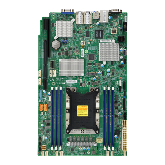
Introduction Congratulations on purchasing your computer motherboard from an industry leader. Supermicro motherboards are designed to provide you with the highest standards in quality and performance. In additon to the motherboard, several important parts that are included in the retail box are listed below. - Page 9 Chapter 1: Introduction Figure 1-1. X11SPW-CTF Motherboard Image Note: All graphics shown in this manual were based upon the latest PCB revision available at the time of publication of the manual. The motherboard you received may or may not look exactly the same as the graphics shown in this manual.
- Page 10 X11SPW-CTF/-TF User's Manual Figure 1-2. X11SPW-TF Motherboard Image...
- Page 11 Chapter 1: Introduction Figure 1-3. X11SPW-CTF Motherboard Layout (not drawn to scale) JUIDB1 COM1 JIPMB1 USB7/8(3.0) IPMI_LAN LAN2 LAN1 USB0/1 Intel MH10 X557 ASpeed COM2 AST2500 MH11 LEDM1 BAR CODE LEDS1 LSI3008 (-CTF only) JBT1 USB9(3.0) Intel C622 USB4/5 M.2 PCI-E 3.0 X4 X11SPW-CTF REV: 1.02...
-
Page 12: Quick Reference
X11SPW-CTF/-TF User's Manual Quick Reference JWD1 USB7/8 (3.0) COM1 IPMI_LAN JUIDB1 JPSAS1 LAN2 USB0/1 JPS1 SXB2 LAN1 JPG1 SXB1A JUIDB1 COM1 JIMPB1 JIPMB1 USB7/8(3.0) COM2 IPMI_LAN LAN2 LAN1 MH10 USB0/1 Intel MH10 JPME2 X557 ASpeed COM2 JPTG1 AST2500 L-SAS0-3 MH11... -
Page 13: Quick Reference Table
Chapter 1: Introduction Quick Reference Table Jumper Description Default Setting JBT1 CMOS Clear Open (Normal) JPG1 VGA Enable/Disable Pins 1-2 (Enabled) JPME2 ME Manufacturing Mode Pins 1-2 (Normal) JPS1 SAS 3.0 Enable/Disable Pins 1-2 (Enabled) JPSAS1 SAS HDD Enable/Disable Pins 1-2 (Enabled) JPTG1 LAN Enable/Disable Pins 1-2 (Enabled) - Page 14 M.2 PCI-E 3.0 X4 or SATA 3.0 Slot MH10, MH11 M.2 Mounting Holes (L-)SAS0-3 Four SAS 3.0 Ports (with RAID 0, 1, 10) (X11SPW-CTF only) (I-)SATA0~7 Intel® PCH SATA 3.0 Ports (with RAID 0, 1, 5, 10) (S-)SATA0~1 SATA 3.0 Ports with SATA DOM Power...
-
Page 15: Motherboard Features
2666MHz in six memory slots Note: Memory speed support depends on the processors used in the system. DIMM Size • Up to 128GB at 1.2V Note: For the latest CPU/memory updates, please refer to our website at http://www.supermicro.com/products/ motherboard. Chipset • Intel PCH C622 Expansion Slots •... - Page 16 Power-on mode for AC power recovery • Wake-on-LAN • Intel® Intelligent Power Node Manager 3.0 (available when the Supermicro Power Manager [SPM] is installed and a special power supply is used. See the note on page 21.) • Management Engine (ME) •...
- Page 17 CPU TDP sizing. Note 2: For IPMI configuration instructions, please refer to the Embedded IPMI Con- figuration User's Guide available at http://www.supermicro.com/support/manuals/. Note 3: It is strongly recommended that you change BMC login information upon initial system power-on.
-
Page 18: System Block Diagram
X11SPW-CTF/-TF User's Manual Figure 1-4. System Block Diagram VCCP0 12v VR13 5+1 PHASE #F-1 #C-1 205W #E-1 #B-1 #D-1 #A-1 VCCP0 SNB CORE PECI:30 DDR-IV SOCKET ID:0 DMI3 PCI-E X8 G3 DMI3 PCI-E X16 G3 PCI-E X16 G3 PCI-E X4 G3... -
Page 19: Processor And Chipset Overview
1.2 Processor and Chipset Overview Built upon the functionality and capability of the Intel® Xeon 81xx/61xx/51xx/41xx/31xx series (Socket P0-LGA3647) processor and the Intel PCH C622 chipset, the X11SPW-CTF/-TF motherboard offers maximum I/O expandability, energy efficiency, and data reliability in a 14-nm process architecture, and is optimized for embedded storage solutions, data centers, and high performance computing. -
Page 20: System Health Monitoring
X11SPW-CTF/-TF User's Manual 1.4 System Health Monitoring Onboard Voltage Monitors An onboard voltage monitor will scan the voltages of onboard chipset, memory, CPU, and battery continuously. Once a voltage becomes unstable, a warning is given, or an error message is sent to the screen. The user can adjust the voltage thresholds to define the sensitivity of the voltage monitor. -
Page 21: Power Supply
As with all computer products, a stable power source is necessary for proper and reliable operation. It is even more important for processors that have high CPU clock rates. The X11SPW-CTF/-TF motherboard accommodates a 24-pin ATX power supply. Although most power supplies generally meet the specifications required by the CPU, some are inadequate. -
Page 22: Chapter 2 Installation
X11SPW-CTF/-TF User's Manual Chapter 2 Installation 2.1 Static-Sensitive Devices Electrostatic Discharge (ESD) can damage electronic com ponents. To prevent damage to your motherboard, it is important to handle it very carefully. The following measures are generally sufficient to protect your equipment from ESD. -
Page 23: Processor And Heatsink Installation
CPU socket cap is in place and that none of the socket pins are bent; otherwise, contact your retailer immediately. • Refer to the Supermicro website for updates on CPU support. • Please follow the instructions given in the ESD Warning section on the first page of this chapter before handling, installing, or removing system components. -
Page 24: Overview Of The Processor Socket Assembly
X11SPW-CTF/-TF User's Manual Overview of the Processor Socket Assembly The processor socket assembly contains 1) the Intel SKX processor, 2) the processor clip, 3) the dust cover, and 4) the CPU socket. 1. SKX Processor 2. Processor Clip (the plastic processor package carrier used for the CPU) 3. -
Page 25: Overview Of The Processor Heatsink Module (Phm)
Chapter 2: Installation Overview of the Processor Heatsink Module (PHM) The Processor Heatsink Module (PHM) contains 1) a heatsink, 2) a processor clip, and 3) the SKX processor. 1. Heatsink 2. Processor Clip 3. SKX Processor Processor Heatsink Module (PHM) (Bottom View for a non-F Model) -
Page 26: Attaching The Non-F Model Processor To The Processor Clip To Create The Processor Carrier Assembly
X11SPW-CTF/-TF User's Manual Attaching the Non-F Model Processor to the Processor Clip to Create the Processor Carrier Assembly To properly install the CPU into the processor clip, please follow the steps below: 1. Locate pin 1 (notch A), which is the triangle located on the top of the processor clip. -
Page 27: Attaching The Non-F Model Processor Carrier Assembly To The Heatsink To Form The Processor Heatsink Module (Phm)
Chapter 2: Installation Attaching the Non-F Model Processor Carrier Assembly to the Heatsink to Form the Processor Heatsink Module (PHM) After you have made a processor carrier assembly by following the instructions on the previous page, please follow the steps below to mount the processor carrier assembly onto the heatsink to create the Processor Heatsink Module (PHM): 1. -
Page 28: Preparing The Cpu Socket For Installation
X11SPW-CTF/-TF User's Manual Preparing the CPU Socket for Installation This motherboard comes with the CPU socket pre-assembled in the factory. The CPU socket contains 1) a dust cover, 2) a socket bracket, 3) the CPU (P0) socket, and 4) a back plate. -
Page 29: Installing The Processor Heatsink Module (Phm)
Chapter 2: Installation Installing the Processor Heatsink Module (PHM) Once you have assembled the processor heatsink module (PHM) by following the instructions listed on page 26, you are ready to install the processor heatsink module (PHM) into the CPU socket on the motherboard. To install the PHM into the CPU socket, follow the instructions below: 1. -
Page 30: Removing The Processor Heatsink Module (Phm) From The Motherboard
X11SPW-CTF/-TF User's Manual Removing the Processor Heatsink Module (PHM) from the Motherboard Before removing the processor heatsink module (PHM), unplug the power cord from the power outlet. 1. Using a T30 Torx-bit screwdriver, turn the screws on the PHM counterclockwise to loosen them from the socket, starting with the screw marked #4 (in the sequence of 4, 3, 2, 1). -
Page 31: Motherboard Installation
ASpeed COM2 AST2500 MH11 LEDM1 BAR CODE LEDS1 LSI3008 (-CTF only) JBT1 USB9(3.0) Intel C622 USB4/5 M.2 PCI-E 3.0 X4 X11SPW-CTF REV: 1.02 DESIGNED IN USA JTPM1 JSTBY1 USB6 BIOS LICENSE JRK1 JPWR3 FAN5 FAN4 FAN7 FAN3 FAN2 FAN1 FAN6... -
Page 32: Installing The Motherboard
X11SPW-CTF/-TF User's Manual Installing the Motherboard 1. Install the I/O shield into the back of the chassis. 2. Locate the mounting holes on the motherboard. See the previous page for the location. 3. Locate the matching mounting holes on the chassis. Align the mounting holes on the motherboard against the mounting holes on the chassis. -
Page 33: Memory Support And Installation
Memory Support The X11SPW-CTF/-TF supports up to 192GB of RDIMM, 384GB of LRDIMM, and 768GB of 3DS LRDIMM DDR4 (288-pin) ECC memory with speeds of up to 2666MHz in six memory slots. Refer to the table below for additional memory information. -
Page 34: Dimm Module Population Sequence
X11SPW-CTF/-TF User's Manual DIMM Module Population Sequence When installing memory modules, the DIMM slots must be populated in the following order: DIMMA1, DIMMD1, DIMMB1, DIMME1, DIMMC1, DIMMF1. • Always use DDR4 memory of the same type, size and speed. •... -
Page 35: Dimm Installation
USB9(3.0) performance, please use the memory Intel C622 USB4/5 modules of the same type and speed. M.2 PCI-E 3.0 X4 X11SPW-CTF REV: 1.02 DESIGNED IN USA JTPM1 2. Push the release tabs outwards on both JSTBY1 USB6 ends of the DIMM slot to unlock it. -
Page 36: Rear I/O Ports
X11SPW-CTF/-TF User's Manual 2.5 Rear I/O Ports See Figure 2-1 below for the locations and descriptions of the various I/O ports on the rear of the motherboard. JUIDB1 COM1 JIPMB1 USB7/8(3.0) IPMI_LAN LAN2 LAN1 USB0/1 Intel MH10 X557 ASpeed COM2... - Page 37 COM2 3. COM2 AST2500 MH11 LEDM1 BAR CODE LEDS1 LSI3008 (-CTF only) JBT1 USB9(3.0) Intel C622 USB4/5 M.2 PCI-E 3.0 X4 X11SPW-CTF REV: 1.02 DESIGNED IN USA JTPM1 JSTBY1 USB6 BIOS LICENSE JRK1 JPWR3 FAN5 FAN4 FAN7 FAN1 FAN6 FAN3...
-
Page 38: Lan Ports
X11SPW-CTF/-TF User's Manual LAN Ports Two 10 Gigabit Ethernet ports (LAN1, LAN2) are located on the I/O back panel. In addition, a dedicated IPMI LAN is located above USB ports 0/1 on the back panel. All of these ports accept RJ45 type cables. Please refer to the LED Indicator section for LAN LED information... - Page 39 2. USB2/3 LEDS1 LSI3008 (-CTF only) 3. USB4/5 JBT1 USB9(3.0) 4. USB6 Intel C622 USB4/5 M.2 PCI-E 3.0 X4 5. USB7/8 X11SPW-CTF REV: 1.02 6. USB9 DESIGNED IN USA JTPM1 7. USB10/11 JSTBY1 USB6 BIOS LICENSE JRK1 JPWR3 FAN5 FAN4...
- Page 40 X11SPW-CTF/-TF User's Manual Unit Identifier Switch/UID LED Indicator A Unit Identifier (UID) switch and an LED Indicator are located on the motherboard. The UID switch is located at JUIDB1, which is next to the VGA port on the back panel. The UID LED (LE1) is located next to the UID switch.
-
Page 41: Front Control Panel
JF1 contains header pins for various buttons and indicators that are normally located on a control panel at the front of the chassis. These connectors are designed specifically for use with Supermicro chassis. See the figure below for the descriptions of the front control panel buttons and LED indicators. - Page 42 X11SPW-CTF/-TF User's Manual NIC1/NIC2 (LAN1/LAN2) The NIC (Network Interface Controller) LED connection for LAN port 1 is located on pins 11 and 12 of JF1, and the LED connection for LAN Port 2 is on Pins 9 and 10. NIC1 LED and NIC2 LED are 2-pin NIC LED headers.
-
Page 43: Power Button
Chapter 2: Installation Power Button The Power Button connection is located on pins 1 and 2 of JF1. Momentarily contacting both pins will power on/off the system. This button can also be configured to function as a suspend button (with a setting in the BIOS - see Chapter 4). To turn off the power in the suspend mode, press the button for at least 4 seconds. -
Page 44: Nmi Button
X11SPW-CTF/-TF User's Manual UID LED The UID LED is on pins 7 and 8 of JF1. Connect a cable here to show the UID activity. Refer to the table below for pin definitions. UID LED Pin Definitions (JF1) Pins Definition... -
Page 45: Connectors
ASpeed COM2 AST2500 MH11 LEDM1 BAR CODE LEDS1 LSI3008 (-CTF only) JBT1 USB9(3.0) Intel C622 USB4/5 M.2 PCI-E 3.0 X4 X11SPW-CTF REV: 1.02 DESIGNED IN USA JTPM1 JSTBY1 USB6 BIOS LICENSE JRK1 JPWR3 FAN4 FAN5 FAN7 FAN6 FAN3 FAN2 FAN1... - Page 46 X11SPW-CTF/-TF User's Manual Secondary Power Connector JPWR1 must also be connected to the power supply. This connector is used to power the processor. +12V 8-pin Power Pin Definitions Pin# Definition 1 - 4 Ground 5 - 8 +12V Required Connection...
-
Page 47: Headers
BAR CODE 4. FAN4 LEDS1 LSI3008 5. FAN5 (-CTF only) JBT1 USB9(3.0) 6. FAN6 Intel C622 USB4/5 7. FAN7 M.2 PCI-E 3.0 X4 X11SPW-CTF REV: 1.02 DESIGNED IN USA JTPM1 JSTBY1 USB6 BIOS LICENSE JRK1 JPWR3 FAN5 FAN4 FAN7 FAN3 FAN2... - Page 48 X11SPW-CTF/-TF User's Manual SGPIO Headers I-SGPIO1, I-SGPIO2 and S-SGPIO1 (Serial General Purpose Input/Output) headers are used to communicate with the enclosure management chip on the backplane. SGPIO Header Pin Definitions Pin# Definition Pin# Definition Ground DATA Out Load Ground Clock...
- Page 49 ASpeed COM2 AST2500 MH11 LEDM1 BAR CODE LEDS1 LSI3008 (-CTF only) JBT1 USB9(3.0) Intel C622 USB4/5 M.2 PCI-E 3.0 X4 X11SPW-CTF REV: 1.02 DESIGNED IN USA JTPM1 JSTBY1 USB6 BIOS LICENSE JRK1 JPWR3 FAN5 FAN4 FAN7 FAN3 FAN2 FAN1 FAN6...
- Page 50 X11SPW-CTF/-TF User's Manual Standby Power The Standby Power header is located at JSTBY1 on the motherboard. See the table below for pin definitions. Standby Power Pin Definitions Pin# Definition +5V Standby Ground No Connection Internal Speaker/Buzzer The Internal Speaker/Buzzer (SP1) is used to provide audible indications for various beep codes.
- Page 51 ASpeed COM2 AST2500 MH11 LEDM1 BAR CODE LEDS1 LSI3008 (-CTF only) JBT1 USB9(3.0) Intel C622 USB4/5 M.2 PCI-E 3.0 X4 X11SPW-CTF REV: 1.02 DESIGNED IN USA JTPM1 JSTBY1 USB6 BIOS LICENSE JRK1 JPWR3 FAN5 FAN4 FAN7 FAN3 FAN2 FAN1 FAN6...
-
Page 52: Chassis Intrusion
X11SPW-CTF/-TF User's Manual Overheat/Fan Fail LED Header Connect an LED indicator to JOH1 to display warnings of chassis overheating and fan failure. See the table below for the LED status. Overheat LED Header Status State Definition Solid Overheat Blinking Fan Fail Chassis Intrusion A Chassis Intrusion header is located at JL1 on the motherboard. - Page 53 The X11SPW-CTF/-TF has eight I-SATA 3.0 ports and two S-SATA 3.0 ports that are supported by the Intel C622 chipset. In addition to the SATA 3.0 ports, the X11SPW-CTF has four SAS 3.0 ports that are supported by the LSI 3008 controller.
- Page 54 X11SPW-CTF/-TF User's Manual Intel RAID Key Header The JRK1 header allows the user to enable RAID functions. Refer to the table below for pin definitions. Intel RAID Key Header Pin Definitions Pin# Defintion PU 3.3V Stdby PCH RAID KEY 1. RAID Key...
- Page 55 Chapter 2: Installation NVMe I C Header Connector JNVI C1 is a management header for the Supermicro AOC NVMe PCI-E peripheral cards. Connect the I C cable to this connector. Power LED/Speaker Pins 1-3 of JD1 are used for power LED indication, and pins 4-7 are for the speaker. Please note that the speaker connector pins (4-7) are used with an external speaker.
-
Page 56: Jumper Settings
X11SPW-CTF/-TF User's Manual 2.8 Jumper Settings How Jumpers Work To modify the operation of the motherboard, jumpers can be used to choose between optional settings. Jumpers create shorts between two pins to change the function of the connector. Pin 1 is identified with a square solder pad on the printed circuit board. See the diagram below for an example of jumping pins 1 and 2. - Page 57 ASpeed COM2 AST2500 MH11 LEDM1 BAR CODE LEDS1 LSI3008 (-CTF only) JBT1 USB9(3.0) Intel C622 USB4/5 M.2 PCI-E 3.0 X4 X11SPW-CTF REV: 1.02 DESIGNED IN USA JTPM1 JSTBY1 USB6 BIOS LICENSE JRK1 JPWR3 FAN5 FAN4 FAN7 FAN3 FAN2 FAN1 FAN6...
- Page 58 X11SPW-CTF/-TF User's Manual Watch Dog JWD1 controls the Watch Dog function. Watch Dog is a monitor that can reboot the system when a software application hangs. Jumping pins 1-2 will cause Watch Dog to reset the system if an application hangs. Jumping pins 2-3 will generate a non-maskable interrupt signal for the application that hangs.
- Page 59 Chapter 2: Installation SAS HDD Enable/Disable (X11SPW-CTF only) JPSAS1 allows you to enable the SAS HDD. See the table below for jumper settings. SAS HDD Jumper Settings Jumper Setting Definition Pins 1-2 Enabled Pins 2-3 Disabled SAS 3.0 Enable/Disable (X11SPW-CTF only) JPS1 allows you to enable the onboard SAS 3.0 ports.
- Page 60 X11SPW-CTF/-TF User's Manual ME Manufacturing Mode Close JPME2 to bypass SPI flash security and force the system to use the Manufacturing Mode, which will allow you to flash the system firmware from a host server to modify system settings. See the table below for jumper settings.
-
Page 61: Led Indicators
AST2500 MH11 LEDM1 2. IPMI LAN LED BAR CODE LEDS1 LSI3008 (-CTF only) JBT1 USB9(3.0) Intel C622 USB4/5 M.2 PCI-E 3.0 X4 X11SPW-CTF REV: 1.02 DESIGNED IN USA JTPM1 JSTBY1 USB6 BIOS LICENSE JRK1 JPWR3 FAN5 FAN4 FAN7 FAN6 FAN3... - Page 62 X11SPW-CTF/-TF User's Manual Onboard Power LED LE2 is an Onboard Power LED. When this LED is lit, it means power is present on the motherboard. In suspend mode, this LED will blink on and off. Be sure to turn off the system and unplug the power cord(s) before removing or installing components.
- Page 63 Chapter 2: Installation SAS Activity LED (X11SPW-CTF only) A SAS Activity LED is located at LEDS1. When LEDS1 flashes, it indicates activity on a SAS port. SAS Activity LED Indicator LED Color Definition Green: SAS Active Blinking SAS Error Unit ID LED A rear UID LED indicator at LE1 is located near the UID switch on the I/O back panel.
- Page 64 X11SPW-CTF/-TF User's Manual M.2 LED The M.2 LED is located at LE3. When LE3 is blinking, M.2 functions normally. Refer to the table below for more information M.2 LED State LED Color Definition Green: Device is working Blinking 1. M.2 LED...
-
Page 65: Chapter 3 Troubleshooting
Chapter 3: Troubleshooting Chapter 3 Troubleshooting 3.1 Troubleshooting Procedures Use the following procedures to troubleshoot your system. If you have followed all of the procedures below and still need assistance, refer to the ‘Technical Support Procedures’ and/ or ‘Returning Merchandise for Service’ section(s) in this chapter. Always disconnect the AC power cord before adding, changing or installing any non hot-swap hardware components. -
Page 66: No Video
1. Make sure that the memory modules are compatible with the system and that the DIMMs are properly and fully installed. (For memory compatibility, refer to the memory compatibility chart posted on our website at http://www.supermicro.com.) 2. Check if different speeds of DIMMs have been installed. It is strongly recommended that you use the same RAM type and speed for all DIMMs in the system. -
Page 67: Losing The System's Setup Configuration
2. Memory support: Make sure that the memory modules are supported by testing the modules using memtest86 or a similar utility. Note: Refer to the product page on our website at http:\\www.supermicro.com memory and CPU support and updates. 3. HDD support: Make sure that all hard disk drives (HDDs) work properly. Replace the bad HDDs with good ones. - Page 68 X11SPW-CTF/-TF User's Manual B. If the system becomes unstable before or during OS installation, check the following: 1. Source of installation: Make sure that the devices used for installation are working properly, including boot devices such as CD/DVD. 2. Cable connection: Check to make sure that all cables are connected and working properly.
-
Page 69: Technical Support Procedures
Before contacting Technical Support, please take the following steps. Also, please note that as a motherboard manufacturer, Supermicro also sells motherboards through its channels, so it is best to first check with your distributor or reseller for troubleshooting services. They should know of any possible problems with the specific system configuration that was sold to you. -
Page 70: Frequently Asked Questions
Updated BIOS files are located on our website at http://www. supermicro.com. Please check our BIOS warning message and the information on how to update your BIOS on our website. Select your motherboard model and download the BIOS file to your computer. -
Page 71: Battery Removal And Installation
Chapter 3: Troubleshooting 3.4 Battery Removal and Installation Battery Removal To remove the onboard battery, follow the steps below: 1. Power off your system and unplug your power cable. 2. Locate the onboard battery as shown below. 3. Using a tool such as a pen or a small screwdriver, push the battery lock outwards to unlock it. -
Page 72: Returning Merchandise For Service
X11SPW-CTF/-TF User's Manual 3.5 Returning Merchandise for Service A receipt or copy of your invoice marked with the date of purchase is required before any warranty service will be rendered. You can obtain service by calling your vendor for a Returned Merchandise Authorization (RMA) number. -
Page 73: Chapter 4 Bios
Chapter 4: BIOS Chapter 4 BIOS 4.1 Introduction This chapter describes the AMIBIOS™ Setup utility for the motherboard. The BIOS is stored on a chip and can be easily upgraded using a flash program. Note: Due to periodic changes to the BIOS, some settings may have been added or deleted and might not yet be recorded in this manual. -
Page 74: Main Setup
X11SPW-CTF/-TF User's Manual 4.2 Main Setup When you first enter the AMI BIOS setup utility, you will enter the Main setup screen. You can always return to the Main setup screen by selecting the Main tab on the top of the screen. - Page 75 Chapter 4: BIOS CPLD Version This item displays the Complex Programmable Logic Device version. Memory Information Total Memory This item displays the total size of memory available in the system.
-
Page 76: Advanced Setup Configurations
X11SPW-CTF/-TF User's Manual 4.3 Advanced Setup Configurations Use the arrow keys to select Boot Setup and press <Enter> to access the submenu items. Warning: Take caution when changing the Advanced settings. An incorrect value, a very high DRAM frequency, or an incorrect DRAM timing setting may make the system unstable. When this occurs, revert to default manufacturer settings. - Page 77 Chapter 4: BIOS Wait For "F1" If Error Use this feature to force the system to wait until the "F1" key is pressed if an error occurs. The options are Disabled and Enabled. INT19 (Interrupt 19) Trap Response Interrupt 19 is the software interrupt that handles the disk function. When this item is set to Immediate, the ROM BIOS of the host adaptors will "capture"...
- Page 78 X11SPW-CTF/-TF User's Manual Power Button Function This feature controls how the system shuts down when the power button is pressed. Select 4 Seconds Override for the user to power off the system after pressing and holding the power button for 4 seconds or longer. Select Instant Off to instantly power off the system as soon as the user presses the power button.
- Page 79 Chapter 4: BIOS Execute Disable Bit (Available if supported by the OS & the CPU) Select Enabled to enable the Execute-Disable Bit, which will allow the processor to designate areas in the system memory where an application code can execute and where it cannot, thus preventing a worm or a virus from flooding illegal codes to overwhelm the processor or damage the system during an attack.
-
Page 80: Advanced Power Management Configuration
X11SPW-CTF/-TF User's Manual AES-NI Select Enable to use the Intel Advanced Encryption Standard (AES) New Instructions (NI) to ensure data security. The options are Disable and Enable. Advanced Power Management Configuration CPU P State Control This feature allows the user to configure the following CPU power settings:... -
Page 81: Chipset Configuration
Chapter 4: BIOS CPU C State Control Autonomous Core C-State Enabling this setting allows the hardware to autonomously choose to enter a C-state based on power consumption and clock speed. The options are Disable and Enable. CPU C6 Report Select Enable to allow the BIOS to report the CPU C6 State (ACPI C3) to the operating system. - Page 82 X11SPW-CTF/-TF User's Manual UPI Configuration The following UPI information will display: • Number of CPU • Number of IIO • Current UPI Link Speed • Current UPI Link Frequency • UPI Global MMIO Low Base / Limit • UPI Global MMIO High Base / Limit •...
- Page 83 Chapter 4: BIOS Memory Configuration Enforce POR Select POR (Plan of Record) to enforce POR restrictions on DDR4 frequency and volt- age programming. The options are POR and Disable. Memory Frequency Use this feature to set the maximum memory frequency for onboard memory modules. The options are Auto, 1866, 2000, 2133, 2200, 2400, 2600, and 2666.
- Page 84 X11SPW-CTF/-TF User's Manual Mirror Mode This feature allows memory to be mirrored between two channels, providing 100% redundancy. The options are Disable, Mirror Mode 1LM, and Mirror Mode 2LM. UEFI ARM Mirror Select Enable to support the UEFI-based address range mirroring with setup option.
-
Page 85: Iio Configuration
Chapter 4: BIOS IIO Configuration EV DFX Features When this feature is set to Enable, the EV_DFX Lock Bits that are located on a proces- sor will always remain clear during electric tuning. The options are Disable and Enable. CPU Configuration IOU0 (II0 PCIe Br1) This item configures the PCI-E port Bifuraction setting for a PCI-E port specified by the... - Page 86 X11SPW-CTF/-TF User's Manual Relaxed Ordering Select Enable to enable Relaxed Ordering support, which will allow certain transac- tions to violate the strict-ordering rules of PCI bus for a transaction to be completed prior to other transactions that have already been enqueued. The options are Disable and Enable.
-
Page 87: South Bridge
Chapter 4: BIOS ntel® VMD Technology Intel® VMD for Volume Management Device on CPU VMD Config for PStack0~PStack2 Intel® VMD for Volume Management Device Select Enable to use the Intel Volume Management Device Technology for this stack. The options are Disable and Enable. *If the item "Intel VMD for Volume Management Device"... -
Page 88: Server Me Configuration
X11SPW-CTF/-TF User's Manual Server ME Configuration The following General ME Configuration will display: • Oper. Firmware Version • Backup Firmware Version • Recovery Firmware Version • ME Firmware Status #1 • ME Firmware Status #2 • Current State • Error Code PCH SATA Configuration... - Page 89 Chapter 4: BIOS SATA RSTe Boot Info Select Enable to provide full int13h support for the devices attached to SATA controller The options are Disable and Enable. SATA RAID Option ROM/UEFI Driver Select UEFI to load the EFI driver for system boot. Select Legacy to load a legacy driver for system boot.
- Page 90 X11SPW-CTF/-TF User's Manual SATA HDD Unlock This feature allows the user to remove any password-protected SATA disk drives. The options are Disable and Enable. Aggressive Link Power Management When this item is set to Enable, the SATA AHCI controller manages the power usage of the SATA link.
- Page 91 Chapter 4: BIOS PCIe/PCI/PnP Configuration The following information will display: • PCI Bus Driver Version • PCI Devices Common Settings: Above 4G Decoding (Available if the system supports 64-bit PCI decoding) Select Enabled to decode a PCI device that supports 64-bit in the space above 4G Address. The options are Disabled and Enabled.
-
Page 92: Network Stack Configuration
X11SPW-CTF/-TF User's Manual VGA Priority Use this feature to select VGA priority when multiple VGA devices are detected. Select On- board to give priority to your onboard video device. Select Offboard to give priority to your graphics card. The options are Onboard and Offboard. -
Page 93: Super Io Configuration
Chapter 4: BIOS IPv6 PXE Support Select Enabled to enable IPv6 PXE boot support. The options are Disabled and Enabled. IPv6 HTTP Support Select Enabled to enable IPv6 HTTP boot support. The options are Disabled and Enabled. PXE Boot Wait Time Use this option to specify the wait time to press the ESC key to abort the PXE boot. -
Page 94: Serial Port Console Redirection
X11SPW-CTF/-TF User's Manual Serial Port 2 Select Enabled to enable the selected onboard serial port. The options are Disabled and Enabled. Device Settings This item displays the status of a serial part specified by the user. Serial Port 2 Change Settings This feature specifies the base I/O port address and the Interrupt Request address of a serial port specified by the user. - Page 95 Chapter 4: BIOS COM1 Bits Per Second Use this feature to set the transmission speed for a serial port used in Console Redirection. Make sure that the same speed is used in the host computer and the client computer. A lower transmission speed may be required for long and busy lines.
- Page 96 X11SPW-CTF/-TF User's Manual COM1 Legacy OS Redirection Resolution Use this feature to select the number of rows and columns used in Console Redirection for legacy OS support. The options are 80x24 and 80x25. COM1 Putty KeyPad This feature selects the settings for Function Keys and KeyPad used for Putty, which is a terminal emulator designed for the Windows OS.
- Page 97 Chapter 4: BIOS COM2 Parity A parity bit can be sent along with regular data bits to detect data transmission errors. Select Even if the parity bit is set to 0, and the number of 1's in data bits is even. Select Odd if the parity bit is set to 0, and the number of 1's in data bits is odd.
- Page 98 X11SPW-CTF/-TF User's Manual COM2 Redirection After BIOS POST Use this feature to enable or disable legacy Console Redirection after BIOS POST. When set to Bootloader, legacy Console Redirection is disabled before booting the OS. When set to Always Enable, legacy Console Redirection remains enabled when booting the OS.
-
Page 99: Acpi Settings
Chapter 4: BIOS Flow Control Use this item to set the flow control for Console Redirection to prevent data loss caused by buffer overflow. Send a "Stop" signal to stop sending data when the receiving buffer is full. Send a "Start" signal to start sending data when the receiving buffer is empty. The options are None, Hardware RTS/CTS, and Software Xon/Xoff. -
Page 100: Iscsi Configuration
X11SPW-CTF/-TF User's Manual iSCSI Configuration iSCSI Initiator Name This feature allows the user to enter the unique name of the iSCSI Initiator in IQN format. Once the name of the iSCSI Initiator is entered into the system, configure the proper settings for the following items. -
Page 101: Event Logs
Chapter 4: BIOS 4.4 Event Logs Use this feature to configure Event Log settings. Change SMBIOS Event Log Settings Enabling/Disabling Options SMBIOS Event Log Change this item to enable or disable all features of the SMBIOS Event Logging during system boot. -
Page 102: View Smbios Event Log
X11SPW-CTF/-TF User's Manual SMBIOS Event Log Standard Settings Log System Boot Event This option toggles the System Boot Event logging to enabled or disabled. The options are Disabled and Enabled. MECI The Multiple Event Count Increment (MECI) counter counts the number of occurences that a duplicate event must happen before the MECI counter is incremented. -
Page 103: Ipmi
Chapter 4: BIOS 4.5 IPMI Use this feature to configure Intelligent Platform Management Interface (IPMI) settings. BMC Firmware Revision This item indicates the IPMI firmware revision used in your system. IPMI Status (Baseboard Management Controller) This item indicates the status of the IPMI firmware installed in your system. System Event Log Enabling/Disabling Options SEL Components... -
Page 104: Bmc Network Configuration
X11SPW-CTF/-TF User's Manual When SEL is Full This feature allows the user to decide what the BIOS should do when the system event log is full. Select Erase Immediately to erase all events in the log when the system event log is full. - Page 105 Chapter 4: BIOS Station MAC Address This item displays the Station MAC address for this computer. Mac addresses are 6 two-digit hexadecimal numbers. Gateway IP Address This item displays the Gateway IP address for this computer. This should be in decimal and in dotted quad form (i.e., 172.31.0.1).
-
Page 106: Security
X11SPW-CTF/-TF User's Manual 4.6 Security This menu allows the user to configure the following security settings for the system. Administrator Password Press Enter to create a new, or change an existing, Administrator password. User Password Press Enter to create a new, or change an existing, User password. - Page 107 Chapter 4: BIOS Secure Boot Mode Use this item to configure Secure Boot variables without authentication. The options are Standard and Custom. CSM Support Select Enabled to support the EFI Compatibility Support Module (CSM), which provides compatibility support for traditional legacy BIOS for system boot. The options are Enabled and Disabled.
- Page 108 X11SPW-CTF/-TF User's Manual Key Exchange Key Set New Select Yes to load the KEK from the manufacturer's defaults. Select No to load the KEK from a file. The options are Yes and No. Append Select Yes to add the KEK from the manufacturer's defaults list to the existing KEK.
- Page 109 Chapter 4: BIOS OsRecovery Signature This item uploads and installs an OSRecovery Signature. You may insert a factory default key or load from a file. The file formats accepted are: 1) Public Key Certificate a. EFI Signature List b. EFI CERT X509 (DER Encoded) c.
-
Page 110: Boot
X11SPW-CTF/-TF User's Manual 4.7 Boot Use this feature to configure Boot Settings. Boot Mode Select Use this item to select the type of device that the system is going to boot from. The options are Legacy, UEFI, and Dual. Legacy to EFI Support This feature enables the system to boot to EFI OS if boot fails from Legacy boot order. - Page 111 Chapter 4: BIOS • Legacy/UEFI/Dual Boot Option #7 • Legacy/UEFI/Dual Boot Option #8 • UEFI/Dual Boot Option #9 • Dual Boot Option #10 • Dual Boot Option #11 • Dual Boot Option #12 • Dual Boot Option #13 • Dual Boot Option #14 •...
-
Page 112: Add New Boot Option
X11SPW-CTF/-TF User's Manual *If any storage media is detected, the following items will become available for configuration: Add New Boot Option This feature allows the user to add a new boot option to the boot priority features for your system. -
Page 113: Save & Exit
Chapter 4: BIOS 4.8 Save & Exit Use this feature to save, discard, and reset setting changes. Save Options Discard Changes and Exit Select this option to quit the BIOS Setup without making any permanent changes to the system configuration, and reboot the computer. Select Discard Changes and Exit from the Save &... - Page 114 X11SPW-CTF/-TF User's Manual Default Options Restore Optimized Defaults To set this feature, select Restore Defaults from the Save & Exit menu and press <Enter>. These are factory settings designed for maximum system stability, but not for maximum performance. Save As User Defaults To set this feature, select Save as User Defaults from the Save &...
-
Page 115: Appendix A Bios Codes
Appendix A: BIOS Codes Appendix A BIOS Codes A.1 BIOS Error POST (Beep) Codes During the POST (Power-On Self-Test) routines, which are performed each time the system is powered on, errors may occur. Non-fatal errors are those which, in most cases, allow the system to continue the boot-up process. - Page 116 When BIOS performs the Power On Self Test, it writes checkpoint codes to I/O port 0080h. If the computer cannot complete the boot process, a diagnostic card can be attached to the computer to read I/O port 0080h (Supermicro p/n AOC-LPC80-20). For information on AMI updates, please refer to http://www.ami.com/products/.
-
Page 117: Appendix B Software Installation
Appendix B Software Installation B.1 Installing Software Programs The Supermicro FTP site contains drivers and utilities for your system at ftp://ftp.supermicro. com. Some of these must be installed, such as the chipset driver. After accessing the FTP site, go into the CDR_Images directory and locate the ISO file for your motherboard. -
Page 118: Superdoctor ® 5
SATA settings back to your original settings. B.2 SuperDoctor ® The Supermicro SuperDoctor 5 is a hardware monitoring program that functions in a command-line or web-based interface in Windows and Linux operating systems. The program monitors system health information such as CPU temperature, system voltages, system power consumption, fan speed, and provides alerts via email or Simple Network Management Protocol (SNMP). -
Page 119: Appendix C Standardized Warning Statements
The following statements are industry standard warnings, provided to warn the user of situations which have the potential for bodily injury. Should you have questions or experience difficulty, contact Supermicro's Technical Support department for assistance. Only certified technicians should attempt to install or configure components. - Page 120 X11SPW-CTF/-TF User's Manual Attention Danger d'explosion si la pile n'est pas remplacée correctement. Ne la remplacer que par une pile de type semblable ou équivalent, recommandée par le fabricant. Jeter les piles usagées conformément aux instructions du fabricant. ¡Advertencia! Existe peligro de explosión si la batería se reemplaza de manera incorrecta. Reemplazar la batería exclusivamente con el mismo tipo o el equivalente recomendado por el fabricante.
-
Page 121: Product Disposal
Appendix C: Warning Statements Product Disposal Warning! Ultimate disposal of this product should be handled according to all national laws and regulations. 製品の廃棄 この製品を廃棄処分する場合、 国の関係する全ての法律 ・ 条例に従い処理する必要があります。 警告 本产品的废弃处理应根据所有国家的法律和规章进行。 警告 本產品的廢棄處理應根據所有國家的法律和規章進行。 Warnung Die Entsorgung dieses Produkts sollte gemäß allen Bestimmungen und Gesetzen des Landes erfolgen. -
Page 122: Appendix D Uefi Bios Recovery
Warning: Do not upgrade the BIOS unless your system has a BIOS-related issue. Flashing the wrong BIOS can cause irreparable damage to the system. In no event shall Supermicro be liable for direct, indirect, special, incidental, or consequential damages arising from a BIOS update. - Page 123 USB device or a writable CD/DVD. Note: If you cannot locate the "Super.ROM" file in your driver disk, visit our website www.supermicro.com to download the BIOS image into a USB flash device and rename it "Super.ROM" for BIOS recovery use.
- Page 124 X11SPW-CTF/-TF User's Manual 4. After locating the new BIOS binary image, the system will enter the BIOS Recovery menu as shown below. Note: At this point, you may decide if you want to start the BIOS recovery. If you decide to proceed with BIOS recovery, follow the procedures below.
- Page 125 Appendix D: UEFI BIOS Recovery 6. After the BIOS recovery process is completed, press any key to reboot the system. 7. Using a different system, extract the BIOS package into a USB flash drive. 8. Press <Del> continuously during system boot to enter the BIOS setup utility. From the top of the tool bar, click on Boot and press <Enter>...
- Page 126 X11SPW-CTF/-TF User's Manual 9. When the UEFI Shell prompt appears, type fs# to change the device directory path. Go to the directory that contains the BIOS package you extracted earlier from Step 7. Enter flash.nsh BIOSname.### at the prompt to start the BIOS update process.
Need help?
Do you have a question about the X11SPW-CTF and is the answer not in the manual?
Questions and answers