Table of Contents
Advertisement
Quick Links
Advertisement
Table of Contents

Related Manuals for Supermicro X11SCA


Summary of Contents for Supermicro X11SCA
- Page 1 X11SCA X11SCA-W X11SCA-F USER MANUAL Revision 1.0...
- Page 2 State of California, USA. The State of California, County of Santa Clara shall be the exclusive venue for the resolution of any such disputes. Supermicro's total liability for all claims will not exceed the price paid for the hardware product.
- Page 3 About This Manual This manual is written for system integrators, IT technicians, and knowledgeable end users. It provides information for the installation and use of the X11SCA/-W/-F motherboard. About This Motherboard The X11SCA/-W/-F motherboards support Intel® Xeon® E3 Core™ i3, Pentium, and Celeron processors in an LGA 1151 (H4) socket.
- Page 4 X11SCA/-W/-F User Manual Contacting Supermicro Headquarters Address: Super Micro Computer, Inc. 980 Rock Ave. San Jose, CA 95131 U.S.A. Tel: +1 (408) 503-8000 Fax: +1 (408) 503-8008 Email: marketing@supermicro.com (General Information) support@supermicro.com (Technical Support) Website: www.supermicro.com Europe Address: Super Micro Computer B.V.
-
Page 5: Table Of Contents
Preface Table of Contents Chapter 1 Introduction 1.1 Checklist ..........................8 Quick Reference .......................15 Quick Reference Table ......................16 Motherboard Features .......................18 1.2 Processor and Chipset Overview ..................22 1.3 Special Features ........................22 Recovery from AC Power Loss ..................22 1.4 System Health Monitoring ....................23 Onboard Voltage Monitors ....................23 Fan Status Monitor with Firmware Control ...............23 Environmental Temperature Control .................23... - Page 6 X11SCA/-W/-F User Manual Removing Memory Modules .....................33 DIMM Module Population Sequence ................34 2.5 M.2 Installation (optional) ....................35 2.6 Rear I/O Ports ........................36 2.7 Front Control Panel ......................40 2.8 Connectors .........................45 Power Connections ......................45 Headers ..........................47 2.9 Jumper Settings .........................54 How Jumpers Work ......................54 2.10 LED Indicators ........................59...
- Page 7 Preface 4.6 Security ..........................100 4.7 Boot ..........................101 4.8 Save & Exit ........................102 Appendix A BIOS Codes Appendix B Software Installation B.1 Installing Software Programs ...................105 Appendix C Standardized Warning Statements Battery Handling ......................107 Product Disposal ......................109 Appendix D UEFI BIOS Recovery...
-
Page 8: Checklist
• Product safety info: http://www.supermicro.com/about/policies/safety_information.cfm • If you have any questions, please contact our support team at: support@supermicro.com This manual may be periodically updated without notice. Please check the Supermicro website for possible updates to the manual revision level. -
Page 9: Chapter 1 Introduction
Chapter 1: Introduction Figure 1-1. X11SCA Motherboard Image Note: All graphics shown in this manual were based upon the latest PCB revision available at the time of publication of the manual. The motherboard you received may or may not look exactly the same as the graphics shown in this manual. - Page 10 X11SCA/-W/-F User Manual Figure 1-2. X11SCA-W Motherboard Image Note: All graphics shown in this manual were based upon the latest PCB revision available at the time of publication of the manual. The motherboard you received may or may not look exactly the same as the graphics shown in this manual.
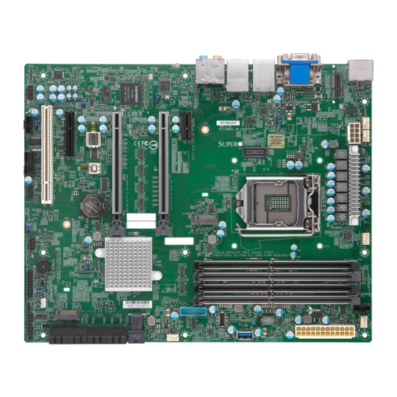
- Page 11 Chapter 1: Introduction Figure 1-2. X11SCA-F Motherboard Image Note: All graphics shown in this manual were based upon the latest PCB revision available at the time of publication of the manual. The motherboard you received may or may not look exactly the same as the graphics shown in this manual.
- Page 12 X11SCA/-W/-F User Manual Figure 1-3. X11SCA Motherboard Layout AUDIO_FP HDMI AUDIO JPL2 LAN2 USB6/7(3.1) LAN1 USB2/3(3.0) SYS_FAN3 JPL1 JPW2 JTBT1 USB0/1 (2.0) PCI-E_M.2-M2 JVR1 JWD1 LED_PWR_SB DIMMA1 DIMMA2 JBT1 DIMMB1 CMOS CLEAR DIMMB2 PCI-E_M.2-M1 U.2-1 JPI2C1 I-SATA4 I-SATA2 I-SATA0 I-SATA5 I-SATA3 I-SATA1 USB8 (3.1,TypeC)
- Page 13 Chapter 1: Introduction Figure 1-3. X11SCA-W Motherboard Layout AUDIO_FP HDMI AUDIO JPL2 USB6/7(3.1) LAN2 USB2/3(3.0) LAN1 WIFI+BT (for X11SCA-W only) SYS_FAN3 JPL1 JPW2 JTBT1 USB0/1 (2.0) PCI-E_M.2-M2 JVR1 JWD1 LED_PWR_SB DIMMA1 DIMMA2 JBT1 DIMMB1 CMOS CLEAR DIMMB2 PCI-E_M.2-M1 U.2-1 JPI2C1...
- Page 14 X11SCA/-W/-F User Manual Figure 1-3. X11SCA-F Motherboard Layout LED4 AUDIO_FP HDMI AUDIO VGA (for X11SCA-F only) JPG1 JPL2 LAN2 USB6/7(3.1) LAN1 USB2/3(3.0) BMC_HB_LED SYS_FAN3 JPL1 JPW2 JTBT1 USB0/1 (2.0) PCI-E_M.2-M2 JVR1 JWD1 LED_PWR_SB DIMMA1 DIMMA2 JBT1 DIMMB1 CMOS CLEAR DIMMB2 PCI-E_M.2-M1...
-
Page 15: Quick Reference
Chapter 1: Introduction Quick Reference LAN1 LAN2 M.2 #3 HDMI USB2/3 USB6/7 HD AUDIO JPL2 LED4 AUDIO_FP AUDIO_FP HDMI AUDIO VGA (for X11SCA-F only) JPB1 JPL2 USB6/7(3.1) LAN2 JPB1 LAN1 USB2/3(3.0) JPL1 BMC_HB_LED WIFI+BT (for X11SCA-W only) JPG1 JPG1 SYS_FAN3 JPL1... -
Page 16: Quick Reference Table
Default Setting JBT1 Clear CMOS Short: Clear CMOS, Open: Normal JPAC1 Audio Enable Pins 1-2 (Enabled) JPG1 BMC GFX Chip Disable (X11SCA-F only) Pins 1-2 (Enabled) JPL1 LAN1 Enable Pins 1-2 (Enabled) JPL2 LAN2 Enable Pins 1-2 (Enabled) JPME2 Manufacturing Mode Select... - Page 17 PCI-E M.2 connectors; small form factor devices and other portable (M1, M2) devices for high speed NVMe SSDs (see Section 2-8) PCI-E M.2 CONNECTOR WiFi + BT (X11SCA-F only) (E1) Internal Speaker/Buzzer SPKR Header for Speaker/Buzzer (Pins 1~4: External Speaker, Pins 3~4:...
-
Page 18: Motherboard Features
Baseboard Management Controller (BMC) • ASpeed AST 2500 Baseboard Managemenr Controller (BMC) supports IPMI 2.0 (X11SCA-F only) • One (1) IPMI LAN shared with LAN2 on the I/O back panel (X11SCA-F only) Graphics • Graphics controller via ASpeed 2500 BMC (X11SCA-F only) I/O Devices •... - Page 19 • Fan status monitoring with firmware • Low noise fan speed control System Management • PECI (Platform Environment Configuration Interface) 3.1 support • IPMI 2.0 (X11SCA-F only) • SuperDoctor® 5, Watch Dog, NMI • Chassis Intrusion header and detection • Power supply monitoring...
- Page 20 Note 1: The CPU maximum thermal design power (TDP) is subject to chassis and heatsink cooling restrictions. For proper thermal management, please check the chas- sis and heatsink specifications for proper CPU TDP sizing. Note 2: For IPMI configuration instructions, please refer to the Embedded IPMI Con- figuration User's Guide available at http://www.supermicro.com/support/manuals/.
- Page 21 Chapter 1: Introduction Figure 1-4. Chipset Block Diagram CPU_PE3_P0~P7 PCIe x16 SLOT #6 SVID IMVP8 VR CPU_PE3_P8~P15 ASM1480 INTEL LGA1151 DDR4 (CHA) DIMMA1 PESLOT2_PRSNT_N PCIe x16 SLOT #4 2133/1866MHz DIMMA2 (Blue) Digital port 1 HDMI 2.0a PS175 DDR4 (CHB) DIMMB1 (Socket H4) Digital port 2 2133/1866MHz...
-
Page 22: Processor And Chipset Overview
Built upon the functionality and capability of the Intel Xeon®-E, Core i3, Celeron, and Pentium series processors (Socket LGA 1151) and the Intel C246, the X11SCA/-W/-F motherboard offers maximum I/O expandability, energy efficiency, and data reliability in a 14-nm process architecture. -
Page 23: System Health Monitoring
Chapter 1: Introduction 1.4 System Health Monitoring Onboard Voltage Monitors (X11SCA-F only) The onboard voltage monitor will continuously scan crucial voltage levels. Once a voltage becomes unstable, it will give a warning or send an error message to the screen. Users can adjust the voltage thresholds to define the sensitivity of the voltage monitor. -
Page 24: Power Supply
As with all computer products, a stable power source is necessary for proper and reliable operation. It is even more important for processors that have high CPU clock rates. The X11SCA/-W/-F motherboard accommodates 24-pin ATX power supplies. Although most power supplies generally meet the specifications required by the CPU, some are inadequate. -
Page 25: Chapter 2 Installation
Chapter 2: Installation Chapter 2 Installation 2.1 Static-Sensitive Devices Electrostatic Discharge (ESD) can damage electronic com ponents. To prevent damage to your motherboard, it is important to handle it very carefully. The following measures are generally sufficient to protect your equipment from ESD. Precautions •... -
Page 26: Motherboard Installation
X11SCA/-W/-F User Manual 2.2 Motherboard Installation All motherboards have standard mounting holes to fit different types of chassis. Make sure that the locations of all the mounting holes for both the motherboard and the chassis match. Although a chassis may have both plastic and metal mounting fasteners, metal ones are highly recommended because they ground the motherboard to the chassis. -
Page 27: Installing The Motherboard
Chapter 2: Installation Installing the Motherboard 1. Locate the mounting holes on the motherboard. See the previous page for the location. 2. Locate the matching mounting holes on the chassis. Align the mounting holes on the motherboard against the mounting holes on the chassis. 3. -
Page 28: Processor And Heatsink Installation
CPU socket cap is in place and none of the socket pins are bent; otherwise, contact your retailer immediately. • Refer to the Supermicro website for updates on CPU support. Installing the LGA1151 Processor 1. Press the load lever to release the load plate, which covers the CPU socket, from its locking position. - Page 29 Chapter 2: Installation 2. Gently lift the load lever to open the load plate. Remove the plastic cap. 3. Use your thumb and your index finger to hold the CPU at the North center edge and the South center edge of the CPU. North Center Edge South Center Edge 4.
- Page 30 X11SCA/-W/-F User Manual 5. Do not rub the CPU against the surface or against any pins of the socket to avoid damaging the CPU or the socket. 6. With the CPU inside the socket, inspect the four corners of the CPU to make sure that the CPU is properly installed.
-
Page 31: Installing A Cpu Heatsink
Chapter 2: Installation Installing a CPU Heatsink 1. Apply the proper amount of thermal grease to the heatsink. 2. Place the heatsink on top of the CPU so that the mounting holes are aligned with those on the retention mechanism. 3. -
Page 32: Removing A Heatsink
X11SCA/-W/-F User Manual Removing a Heatsink Warning: We do not recommend that the CPU or the heatsink be removed. However, if you do need to remove the heatsink, please follow the instructions below to uninstall the heatsink to avoid damaging the CPU or other components. -
Page 33: Memory Support And Installation
Memory Support The X11SCA/-W/-F motherboard supports up to 64GB of unbuffered, ECC/non-ECC DDR4 with speeds up to 2666MHz memory in four memory slots. Populating these DIMM slots with memory modules of the same type and size will result in interleaved memory, which will improve memory performance. -
Page 34: Dimm Module Population Sequence
X11SCA/-W/-F User Manual DIMM Module Population Sequence When installing memory modules, the DIMM slots should be populated in the following order: DIMMA2, DIMMB2, DIMMA1, DIMMB1. • Always use DDR4 DIMM modules of the same type and size. • Mixed DIMM speeds can be installed. However, all DIMMs will run at the speed of the slowest DIMM. -
Page 35: Installation (Optional)
Chapter 2: Installation 2.5 M.2 Installation (optional) Follow the instructions below to properly install an optional M.2 device. Note: The length of the M.2 device being installed will affect the installation process below. Holder Holder Mount Turn 90 degrees Locked position Locked position to lock Card Holder Mount... -
Page 36: Rear I/O Ports
Description Description DisplayPort LAN1 USB2 (USB3.1 Gen 1) 16 SPDIF Out HDMI USB6 (Type-A) Center/LFE Out Mic In WiFi + BT (X11SCA-W USB7 (Type-C) Line In only) VGA (X11SCA-F only) LAN2 Surround Out USB3 (USB3.1 Gen 1) 15 Line Out... - Page 37 Chapter 2: Installation VGA Port (X11SCA-F only) A video (VGA) port is located to the left of LAN1 on the I/O back panel. See the board layout below for the location. Serial Ports One COM connection (COM1) is located on the motherboard. COM1 is located below JTBT1.
- Page 38 X11SCA/-W/-F User Manual Universal Serial Bus (USB) Ports Front Panel USB (2.0) 0/1, 4/5 Pin Definitions There are two USB 3.1 Gen 1 ports (USB2/3) and Pin# Definition Pin# Definition two USB 3.1 Gen 2 ports (USB6/7) located on the I/O back panel.
- Page 39 Chapter 2: Installation LAN Ports Two Gigabit Ethernet ports (LAN1 and LAN2) are located on the I/O back panel of the motherboard. All of these ports accept RJ45 cables. Please refer to the LED Indicator section for LAN LED information. LAN Port Pin Definitions Pin#...
-
Page 40: Front Control Panel
JF1 contains header pins for various buttons and indicators that are normally located on a control panel at the front of the chassis. These connectors are designed specifically for use with Supermicro chassis. See the figure below for the descriptions of the front control panel buttons and LED indicators. - Page 41 Chapter 2: Installation Power Button The Power Button connection is located on pins 1 and 2 of JF1. Momentarily contacting both pins will power on/off the system. This button can also be configured to function as a suspend button (see Chapter 4). To turn off the power when the system is in suspend mode, press the button for 4 seconds or longer.
- Page 42 X11SCA/-W/-F User Manual Overheat (OH)/Fan Fail Connect an LED cable to pins 7 and 8 of the Front Control Panel to use the Overheat/Fan Fail LED connections. The LED on pin 8 provides warnings of overheat or fan failure. See the tables below for pin definitions.
- Page 43 Chapter 2: Installation NIC1/NIC2 (LAN1/LAN2) The NIC (Network Interface Controller) LED connection for LAN port 1 is located on pins 11 and 12 of JF1, and the LED connection for LAN port 2 is on pins 9 and 10. Attach the NIC LED cables here to display network activity.
- Page 44 X11SCA/-W/-F User Manual Power LED The Power LED connection is located on pins 15 and 16 of JF1. See the table below for pin definitions. Power LED Pin Definitions (JF1) Pin# Definition 3.3V PWR LED NMI Button The non-maskable interrupt button header is located on pins 19 and 20 of JF1. See the table below for pin definitions.
-
Page 45: Connectors
Chapter 2: Installation 2.8 Connectors Power Connections Main ATX Power Supply Connector The primary power supply connector (JPW1) meets the ATX SSI EPS 12V specification. You must also connect the 8-pin (JPW2) processor power connector to your power supply. ATX Power 24-pin Connector Pin Definitions Pin# Definition... - Page 46 X11SCA/-W/-F User Manual Secondary Power Connector JPW2 must also be connected to the power supply. This connector is used to power the processor(s). +12V 8-pin Power Pin Definitions Pin# Definition Ground +12V Required Connection Important: To provide adequate power supply to the motherboard, be sure to connect the 24-pin ATX PWR and the 8-pin PWR connectors to the power supply.
-
Page 47: Headers
Headers Fan Headers The X11SCA/-W/-F has five fan headers (FAN1-FAN5). All of these 4-pin fan headers are backwards-compatible with the traditional 3-pin fans. However, fan speed control is only available for 4-pin fans by Thermal Management via the IPMI 2.0 interface. See the table below for pin definitions. - Page 48 X11SCA/-W/-F User Manual Internal Speaker/Buzzer The Internal Speaker (SP1) can be used to provide audible notifications using various beep codes. Refer to the table below for pin definitions. See the layout below for the location of the internal buzzer. Internal Buzzer...
- Page 49 Chapter 2: Installation SGPIO Headers Two I-SGPIO (Serial Link General Purpose Input/Output) headers are located on the motherboard. They support the onboard I-SATA 3.0 ports. See the tables below for pin definitions. SGPIO Header I-SGPIO 1/2 Pin Definitions Pin# Definition Pin# Definition I-SGPIO1...
- Page 50 X11SCA/-W/-F User Manual Standby Power The +5V Standby Power header is located at JSTBY1 on the motherboard. You must have a card with a Standby Power connector and a cable to use this feature. See the table below for pin definitions.
- Page 51 Chapter 2: Installation TPM/Port 80 Header A Trusted Platform Module (TPM)/Port 80 header is located at JTPM1 to provide TPM support and a Port 80 connection. Use this header to enhance system performance and data security. See the table below for pin definitions. Trusted Platform Module Header Pin Definitions Pin#...
- Page 52 X11SCA/-W/-F User Manual M.2 Connection The X11SCA/-W/-F board contains three M.2 connectors, one of which supports Wifi+BT (on back panel). M.2, formerly Next Generation Form Factor (NGFF), serves to replace mini PCI-E and mSATA. M.2 allows for a greater variety of card sizes, increased functionality, and spatial efficiency.
- Page 53 Eight SATA 3.0 connectors, supported by the Intel C246 PCH chip, are located on the X11SCA/-W/-F motherboard. These SATA ports support RAID 0, 1, 5, and 10. SATA ports provide serial-link signal connections, which are faster than the connections of Parallel ATA.
-
Page 54: Jumper Settings
X11SCA/-W/-F User Manual 2.9 Jumper Settings How Jumpers Work To modify the operation of the motherboard, jumpers can be used to choose between optional settings. Jumpers create shorts between two pins to change the function of the connector. Pin 1 is identified with a square solder pad on the printed circuit board. See the diagram below for an example of jumping pins 1 and 2. - Page 55 Chapter 2: Installation CMOS Clear JBT1 is used to clear the CMOS. Instead of pins, this jumper consists of contact pads to prevent accidental clearing of the CMOS. To clear the CMOS, use a metal object such as a small screwdriver to touch both pads at the same time to short the connection. Note: Be sure to completely shut down the system, and then short JBT1 to clear the CMOS.
- Page 56 X11SCA/-W/-F User Manual Watch Dog Watch Dog (JWD1) is a system monitor that can reboot the system when a software application hangs. Close pins 1 and 2 to reset the system if an application hangs. Close pins 2 and 3 to generate a non-maskable interrupt (NMI) signal for the application that hangs.
- Page 57 Chapter 2: Installation LAN Port Enable/Disable Jumpers JPL1 and JPL2 enable or disable LAN ports 1 and 2 respectively on the motherboard. Refer to the table below for jumper settings. The default setting is Enabled. LAN1-LAN2 Enable/Disable Jumper Settings Jumper Setting Definition Pins 1-2 Enabled...
- Page 58 X11SCA/-W/-F User Manual VGA Enable/Disable (X11SCA-F Only) Jumper JPG1 allows the user to enable the onboard VGA connector. The default setting is pins 1 and 2 to enable the connection. See the table below for jumper settings. The default setting is Enabled.
-
Page 59: Led Indicators
Chapter 2: Installation 2.10 LED Indicators LAN LEDs Two LAN ports (LAN 1/2) are located on the I/O back panel of the motherboard. Each Ethernet LAN port has two LEDs. The green LED indicates activity, while the other Link LED may be green, amber, or off to indicate the speed of the connection. - Page 60 X11SCA/-W/-F User Manual Standby Power LED The Standby Power LED is located at LED_PWR_SB on the motherboard. When this LED is on, the system is receiving power. Be sure to turn off the system and unplug the power cord before removing or installing components. See the table below for more information.
-
Page 61: Chapter 3 Troubleshooting
Chapter 3: Troubleshooting Chapter 3 Troubleshooting 3.1 Troubleshooting Procedures Use the following procedures to troubleshoot your system. If you have followed all of the procedures below and still need assistance, refer to the ‘Technical Support Procedures’ and/ or ‘Returning Merchandise for Service’ section(s) in this chapter. Always disconnect the AC power cord before adding, changing or installing any non hot-swap hardware components. -
Page 62: System Boot Failure
1. Make sure that the memory modules are compatible with the system and that the DIMMs are properly and fully installed. (For memory compatibility, refer to the memory compatibility chart posted on our website at http://www.supermicro.com.) 2. Check if different speeds of DIMMs have been installed. It is strongly recommended that you use the same RAM type and speed for all DIMMs in the system. -
Page 63: Losing The System's Setup Configuration
2. Memory support: Make sure that the memory modules are supported by testing the modules using memtest86 or a similar utility. Note: Refer to the product page on our website at http://www.supermicro.com memory and CPU support and updates. 3. HDD support: Make sure that all hard disk drives (HDDs) work properly. Replace the bad HDDs with good ones. - Page 64 X11SCA/-W/-F User Manual 3. Using the minimum configuration for troubleshooting: Remove all unnecessary components (starting with add-on cards first), and use the minimum configuration (but with the CPU and a memory module installed) to identify the trouble areas. Refer to the steps listed in Section A above for proper troubleshooting procedures.
-
Page 65: Technical Support Procedures
Before contacting Technical Support, please take the following steps. Also, please note that as a motherboard manufacturer, Supermicro also sells motherboards through its channels, so it is best to first check with your distributor or reseller for troubleshooting services. They should know of any possible problems with the specific system configuration that was sold to you. -
Page 66: Frequently Asked Questions
Updated BIOS files are located on our website at http://www. supermicro.com. Please check our BIOS warning message and the information on how to update your BIOS on our website. Select your motherboard model and download the BIOS file to your computer. -
Page 67: Battery Removal And Installation
Chapter 3: Troubleshooting 3.4 Battery Removal and Installation Battery Removal To remove the onboard battery, follow the steps below: 1. Power off your system and unplug your power cable. 2. Locate the onboard battery as shown below. 3. Using a tool such as a pen or a small screwdriver, push the battery lock outwards to unlock it. -
Page 68: Returning Merchandise For Service
X11SCA/-W/-F User Manual 3.5 Returning Merchandise for Service A receipt or copy of your invoice marked with the date of purchase is required before any warranty service will be rendered. You can obtain service by calling your vendor for a Returned Merchandise Authorization (RMA) number. -
Page 69: Chapter 4 Bios
BIOS 4.1 Introduction This chapter describes the AMIBIOS™ Setup utility for the X11SCA/-W/-F motherboard. The BIOS is stored on a chip and can be easily upgraded using a flash program. Note: Due to periodic changes to the BIOS, some settings may have been added or deleted and might not yet be recorded in this manual. -
Page 70: Main
X11SCA/-W/-F User Manual 4.2 Main The following information is displayed in this section: • System Date - the date the system is set to • System Time - the time the system is set to • Motherboard Model - the model of the motherboard •... -
Page 71: Advanced
Chapter 4: BIOS 4.3 Advanced Warning: Take caution when changing the Advanced settings. An incorrect value, a very high frequency, or an incorrect timing setting may make the system unstable. If this occurs, revert to the default to the manufacture default settings. Boot Feature ... - Page 72 X11SCA/-W/-F User Manual Wait For "F1" If Error Use this feature to force the system to wait until the "F1" key is pressed if an error occurs. The options are Disabled or Enabled. Re-try Boot If this feature is enabled, the BIOS will automatically reboot the system from a specified boot device after its initial boot failure.
- Page 73 Chapter 4: BIOS • CPU C6 state - displays whether CPU C6 is supported • CPU C7 state - displays whether CPU C7 is supported • CPU C8 state - displays whether CPU C8 is supported • CPU C9 state - displays whether CPU C9 is supported •...
- Page 74 X11SCA/-W/-F User Manual This feature enables Intel CPU Advanced Encryption Standard (AES) Instructions support to enhance data integrity. The options are Disabled or Enabled. Boot performance mode This feature enables the selection of the default CPU performance during system boot. The options are Max Non-Turbo Performance, Power Saving, and Turbo Performance.
- Page 75 Chapter 4: BIOS C states C-State architecture, a processor power management platform developed by Intel, can further reduce power consumption from the basic C1 (Halt State) state that blocks clock cycles to the CPU. Select Enabled for CPU C-State support. The options are Disabled or Enabled. If this feature is set to Enabled, the following items will display: Enhanced C-states This feature enables Enhanced C1 Power State to boost system performance.
- Page 76 X11SCA/-W/-F User Manual Maximum Memory Frequency This feature selects the type/speed of the memory installed. The options are 1333, 1600, 1867, 2133, 2400, 2667, 2933, and 3200. All values are in MHz. Default speed is auto detected. ECC Support This feature enables DDR ECC support. The options are Disabled or Enabled.
- Page 77 Chapter 4: BIOS GTT Size This feature controls the memory allocation size for the graphics translation table (GTT). The options are 2MB, 4MB, and 8MB. Aperture Size This feature controls the graphics aperture size. For optimal performance, select the size that matches the installed graphics card's size.
- Page 78 X11SCA/-W/-F User Manual DMI De-emphasis Control This feature controls the DMI De-emphasis setting. The options are -6 dB or -3.5 dB. PEG Port Configuration CPU SLOT6 PCI-E 3.0 X16 This displays information if a PCI-E device is installed. SLOT6 Max Link Speed Select Auto, Gen1, Gen2, or Gen3 to set the PEG Max Link Speed.
- Page 79 Chapter 4: BIOS Maximum GT frequency This feature defines the Maximum GT Frequency. Choose between 300MHz (RPN) and 1200MHz (RP0). Any value beyond this range will be clipped to its min/max supported by the CPU. The options are Default Max Frequency or 300MHz~1200MHz (in incre- ments of 50MHz).
- Page 80 X11SCA/-W/-F User Manual SLOT7 L1 Substates This feature controls L1 Substates. The options are Disabled, L1.1, and L1.1 & L1.2. This feature enables Precision Time Measurement (PTM). The options are Disabled or Enabled. This feature enables Downstream Port Containment (DPC). The options are Disabled or Enabled.
- Page 81 Chapter 4: BIOS PCH SLOT2 PCI-E 3.0 X4/PCI-E M.2-M1 SLOT2/M.2-M1 ASPM Support This feature controls the Active State Power Management (ASPM) setting. The options are Disabled, L0s, L1, L0sL1, and Auto. SLOT2/M.2-M1 L1 Substates This feature controls L1 Substates. The options are Disabled, L1.1, and L1.1 & L1.2. This feature enables Precision Time Measurement (PTM).
- Page 82 X11SCA/-W/-F User Manual AST2500SEC Super IO Configuration SOL Configuration Serial Port 1 This feature will enable Serial Port 1 (COM1). Click to check the box to enable Serial Port 1. The default is Checked (Enabled). Device Settings Change Settings This feature configures the IRQ setting for Serial Port 1 (COM1).
- Page 83 Chapter 4: BIOS COM1 Parity A parity bit can be sent along with regular data bits to detect data transmission errors. Select Even if the parity bit is set to 0, and the number of 1's in data bits is even. Select Odd if the parity bit is set to 0, and the number of 1's in data bits is odd.
- Page 84 X11SCA/-W/-F User Manual SOL Console Redirection (X11SCA-F only) Check the box to enable SOL Console Redirection, which will allow a client machine to be connected to a host machine at a remote site for networking. The options are Unchecked (Disabled) and Checked (Enabled).
- Page 85 OS. When the Always Enable option is selected, legacy Console Redirection remains enabled upon OS bootup. The options are Always Enable or Bootloader. AMT SOL Console Redirection (X11SCA / X11SCA-W only) Check the box to enable AMT SOL Console Redirection, which will allow a client machine to be connected to a host machine at a remote site for networking.
- Page 86 X11SCA/-W/-F User Manual AMT SOL Bits per second Use this feature to set the transmission speed for a serial port used in Console Redirection. Make sure that the same speed is used in the host computer and the client computer. A lower transmission speed may be required for long and busy lines.
- Page 87 Chapter 4: BIOS AMT SOL Putty KeyPad This feature selects Function Keys and KeyPad settings for Putty, which is a terminal VT100, LINUX, emulator designed for the Windows OS. The options are XTERMR6, SCO, ESCN, and VT400. AMT SOL Redirection After BIOS POST Use this feature to enable or disable legacy Console Redirection after BIOS POST.
- Page 88 X11SCA/-W/-F User Manual EMS Flow Control Use this feature to set the flow control for Console Redirection to prevent data loss caused by buffer overflow. Send a "Stop" signal to stop sending data when the receiving buffer is full. Send a "Start" signal to start sending data when the receiving buffer is empty. The options are None, Hardware RTS/CTS, and Software Xon/Xoff.
- Page 89 ME Firmware SKU ME FW Image Re-Flash This feature enables ME FW Image Re-Flash function. The options are Disabled or Enabled. Manageability Features State (X11SCA/-W only) This feature enables Intel® Manageability features in FW. The options are Disabled or Enabled.
- Page 90 X11SCA/-W/-F User Manual WatchDog This feature enables the WatchDog Timer. The options are Disabled or Enabled. OS Timer If WatchDog (above) is set to Enabled, enter a value for OS Timer. The default is 0. BIOS Timer If WatchDog (above) is set to Enabled, enter a value for BIOS Timer. The default is 0.
- Page 91 Chapter 4: BIOS MEBx Resolution Settings Non-UI Mode Resolution This feature controls the resolution for non-UI text mode. The options are Auto, 80x25, and 100x31. UI Mode Resolution This feature controls the resolution for UI text mode. The options are Auto, 80x25, and 100x31.
- Page 92 Select PXE (Preboot Execution Environment) to boot the computer using a PXE device installed in a specified LAN port. Select Disabled to prevent system boot using a device installed in a LAN port. For X11SCA-F motherboards, the options are iSCSI or PXE. For all others the only option is PXE.
- Page 93 Chapter 4: BIOS Ipv4 PXE Support Select Enabled to enable Ipv4 PXE (Preboot Execution Environment) for boot support. If this feature is set to Disabled, Ipv4 PXE boot option will not be supported. The options are Disabled or Enabled. Ipv4 HTTP Support Select Enabled to enable IPv4 HTTP boot support.
- Page 94 X11SCA/-W/-F User Manual Device Select This feature restricts support to a specific type of security device. The options are TPM 1.2, TPM 2.0, and Auto (both). TPM Enabled Status TPM Active Status TPM Owner Status...
-
Page 95: Event Logs
Chapter 4: BIOS 4.4 Event Logs Change Smbios Event Log Settings Smbios Event Log Use this feature to enable all features of the SMBIOS Event Logging during system boot. The options are Disabled or Enabled. Erase Event Log If No is selected, data stored in the event log will not be erased. Select Yes, Next Reset, data in the event log will be erased upon next system reboot. - Page 96 X11SCA/-W/-F User Manual MECI The Multiple Event Count Increment (MECI) counter counts the number of occurences that a duplicate event must happen before the MECI counter is incremented. This is a numeric value. The default value is 1. METW The Multiple Event Time Window (METW) defines the number of minutes that must pass between duplicate log events before MECI is incremented.
-
Page 97: Ipmi
Chapter 4: BIOS 4.5 IPMI Use this feature to configure Intelligent Platform Management Interface (IPMI) settings. BMC Firmware Revision This feature indicates the IPMI firmware revision used in your system. IPMI Status (Baseboard Management Controller) This feature indicates the status of the IPMI firmware installed in your system. System Event Log SEL Components Select Enabled for all system event logging at bootup. - Page 98 X11SCA/-W/-F User Manual When SEL is Full This feature allows the user to decide what the BIOS should do when the system event log is full. Select Erase Immediately to erase all events in the log when the system event log is full.
- Page 99 Chapter 4: BIOS VLAN This feature enables the IPMI VLAN function. The options are Disabled or Enabled. *If the feature above is set to Enable, the following feature will become available for configuration: VLAN ID Use this feature to enter the VLAN ID. The default setting is 0. IPV6 Support This feature enables LAN1 IPV6 Support.
-
Page 100: Security
X11SCA/-W/-F User Manual 4.6 Security Use this submenu to create Administrator and User passwords. Using ONLY an Administrator password limits access to BIOS setup. Using ONLY a User password will lock unauthorized users from booting the system and/or entering BIOS setup. -
Page 101: Boot
Chapter 4: BIOS 4.7 Boot Setup Prompt Timeout This feature controls how long (in seconds) the boot process will wait for the Setup Activation key (normally <Delete>) to be pressed before moving on. The default is 1. Boot mode select Use this feature to select the boot mode. -
Page 102: Save & Exit
X11SCA/-W/-F User Manual 4.8 Save & Exit Discard Changes and Reset This option will save the changes that have been made and will reboot the system. Save Changes and Reset This option will save the changes that have been made and will reboot the system. - Page 103 Chapter 4: BIOS Boot Override IBA CL Slot 00FE v0113 This feature force boots IBA CL Slot 00FE v0113. This will restart the system. UEFI: Built-in EFI Shell This feature force boots the Built-in EFI Shell.
-
Page 104: Appendix A Bios Codes
X11SCA/-W/-F User Manual Appendix A BIOS Codes BIOS Error POST (Beep) Codes During the POST (Power-On Self-Test) routines, which are performed upon each system boot, errors may occur. Non-fatal errors are those which, in most cases, allow the system to continue to boot. These error messages normally appear on the screen. -
Page 105: Appendix B Software Installation
Appendix B Software Installation B.1 Installing Software Programs The Supermicro FTP site contains drivers and utilities for your system at ftp://ftp.supermicro. com. Some of these must be installed, such as the chipset driver. After accessing the FTP site, go into the CDR_Images directory and locate the ISO file for your motherboard. - Page 106 SuperDoctor ® The Supermicro SuperDoctor 5 is a hardware monitoring program that functions in a command-line or web-based interface in Windows and Linux operating systems. The program monitors system health information, such as CPU temperature, system voltages, system power consumption, and fan speed, and provides alerts via email or the Simple Network Management Protocol (SNMP).
-
Page 107: Appendix C Standardized Warning Statements
The following statements are industry standard warnings, provided to warn the user of situations that might potentially cause bodily injury. Should you have questions or experience difficulty, contact Supermicro's Technical Support department for assistance. Only certified technicians should attempt to install or configure components. - Page 108 X11SCA/-W/-F User Manual Attention Danger d'explosion si la pile n'est pas remplacée correctement. Ne la remplacer que par une pile de type semblable ou équivalent, recommandée par le fabricant. Jeter les piles usagées conformément aux instructions du fabricant. ¡Advertencia! Existe peligro de explosión si la batería se reemplaza de manera incorrecta. Reemplazar la batería exclusivamente con el mismo tipo o el equivalente recomendado por el fabricante.
-
Page 109: Product Disposal
Appendix C: Warning Statements Product Disposal Warning! Ultimate disposal of this product should be handled according to all national laws and regulations. 製品の廃棄 この製品を廃棄処分する場合、 国の関係する全ての法律 ・ 条例に従い処理する必要があります。 警告 本产品的废弃处理应根据所有国家的法律和规章进行。 警告 本產品的廢棄處理應根據所有國家的法律和規章進行。 Warnung Die Entsorgung dieses Produkts sollte gemäß allen Bestimmungen und Gesetzen des Landes erfolgen. -
Page 110: Appendix D Uefi Bios Recovery
Warning: Do not upgrade the BIOS unless your system has a BIOS-related issue. Flashing the wrong BIOS can cause irreparable damage to the system. In no event shall Supermicro be liable for direct, indirect, special, incidental, or consequential damages arising from a BIOS update. - Page 111 Directory of a USB device or a writeable CD/DVD. Note: If you cannot locate the "Super.ROM" file in your driver disk, visit our website www.supermicro.com to download the BIOS image into a USB flash device and rename it to "Super.ROM" for BIOS recovery use.
- Page 112 X11SCA/-W/-F User Manual Note: At this point, you may decide if you want to start the BIOS recovery. If you decide to proceed with BIOS recovery, follow the procedures below. 4. When the screen shown above displays, use the arrow keys to select the item "Proceed with flash update"...
- Page 113 Appendix D: UEFI BIOS Recovery 5. After the BIOS recovery process is completed, press any key to reboot the system.
Need help?
Do you have a question about the X11SCA and is the answer not in the manual?
Questions and answers